Free-space quantum key distribution
Abstract
A working free-space quantum key distribution (QKD) system has been developed and tested over a 205-m indoor optical path at Los Alamos National Laboratory under fluorescent lighting conditions. Results show that free-space QKD can provide secure real-time key distribution between parties who have a need to communicate secretly.
pacs:
PACS Numbers: 42.79.Sz, 03.65-wQuantum cryptography was introduced in the mid-1980s [1] as a new method for generating the shared, secret random number sequences, or cryptographic keys, that are used in crypto-systems to provide communications security. The appeal of quantum cryptography is that its security is based on laws of Nature, in contrast to existing methods of key distribution that derive their security from the perceived intractability of certain problems in number theory, or from the physical security of the distribution process. Since the introduction of quantum cryptography, several groups have demonstrated that quantum key distribution (QKD) can be performed over multi-kilometer distances of optical fiber [2]-[9], but the utility of the method would be greatly enhanced if it could also be performed over free-space paths, such as are used in laser communications systems. Indeed there are certain key distribution problems in this category for which QKD would have definite practical advantages (for example, it is impractical to send a courier to a satellite). We are developing QKD for use over line-of-sight paths, including surface to satellite, and here we report our first results on key generation over indoor paths of up to m.
The feasibility of QKD over free-space paths might be considered problematic because it requires the transmission of single photons through a medium with varying properties and detection of these photons against a high background. However, others have shown that the combination of sub-nanosecond timing, narrow filters [10, 11], and spatial filtering can render both of these problems tractable. Furthermore, the atmosphere is essentially non-birefringent at optical wavelengths, allowing faithful transmission of the single-photon polarization states used in QKD.
A QKD procedure starts with the sender, “Alice,” generating a secret random binary number sequence. For each bit in the sequence, Alice prepares and transmits a single photon to the recipient, “Bob,” who measures each arriving photon and attempts to identify the bit value Alice has transmitted. Alice’s photon state preparations and Bob’s measurements are chosen from sets of non-orthogonal possibilities. For example, in the B92 protocol [12] Alice agrees with Bob (through public discussion) that she will transmit a horizontally-polarized photon, , for each “0” in her sequence, and a right-circular-polarized photon, , for each “1” in her sequence. Bob agrees with Alice to randomly test the polarization of each arriving photon in one of two ways: he either tests with vertical polarization, , to reveal “1s,” or left-circular polarization, , to reveal “0s.” Note that Bob will never detect a photon for which he and Alice have used a preparation/measurement pair that corresponds to different bit values, such as and , which happens for % of the bits in Alice’s sequence. However, for the other % of Alice’s bits where the preparation and measurement protocols agree, such as and , there is a 50% probability that Bob detects the photon, as shown in TABLE I. So, by detecting photons Bob is able to identify a random % portion of the bits in Alice’s sequence, assuming no bit loss in transmission or detection. (This % efficiency factor is the price that Alice and Bob must pay for secrecy.) Bob then communicates to Alice over a public channel the locations, but not the bit values, in the sequence where he detected photons, and Alice retains only these detected bits from her initial sequence. The resulting detected bit sequences are the raw key material from which a pure key is distilled using classical error detection techniques. An eavesdropper, “Eve,” can neither “tap” the key transmissions, owing to the indivisibility of a photon [13, 14], nor copy them owing to the quantum “no-cloning” [15]-[18] theorem. Furthermore, the non-orthogonal nature of the quantum states ensures that if Eve makes her own measurements she will be detected through the elevated error rate she causes by the irreversible “collapse of the wavefunction” [19].
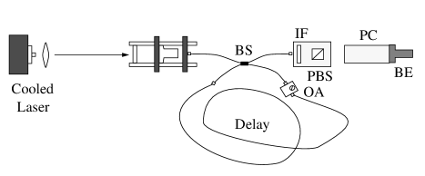
The prototype QKD transmitter (FIG. 1) consisted of a temperature controlled diode laser, a collimating lens, two dielectric mirrors, a fiber to free-space launch system, a single-mode fiber pigtailed polarization neutral beamsplitter, a variable optical attenuator (OA), a -m single-mode optical fiber delay, a nm bandwidth interference filter (IF), a polarizing beamsplitter (PBS), a low-voltage pockels cell (PC), and an beam expander (BE).
The diode laser wavelength is temperature selected to nm, and the laser is configured to emit a short, weak coherent pulse of ns length, containing approximately photons.
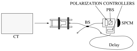
The free-space QKD receiver (FIG. 2) was comprised of a in. Cassegrain telescope (CT), a free-space to fiber launch system, a single-mode fiber pigtailed polarization neutral beamsplitter, two sets of polarization controllers (each consisting of a quarter-wave retarder and a half-wave retarder), a PBS, and a single photon counting module, or SPCM (EG&G part number: SPCM-AQ 142-FL). The prototype receiver did not include an interference filter but it is expected that future versions of the receiver will incorporate this feature to reduce background light levels.
A computer control system, “Alice,” starts the QKD protocol by pulsing the diode laser at a rate previously agreed upon between herself and the receiving computer control system, “Bob.” Each laser pulse is launched into a single-mode optical fiber and then split by the beamsplitter with equal probability between the direct path and the delay path. The direct path produces a coherent “bright pulse” of photons which Bob uses as his system trigger for timing purposes.
Light traveling along the direct path passes through the IF, the PBS, the PC, and is then launched into free-space from the BE. The IF constrains wavelength, and the PBS is oriented to transmit horizontal polarization.
The fiber delay and OA are used to delay the diverted pulse by ns as well as attenuate the diverted pulse to an average of photons per pulse. This attenuated pulse then impinges again upon the beamsplitter, which transmits a dim-pulse with and average of photons that follows the bright pulse along the direct path through the IF, the PBS, the PC, and the BE. (The attenuated pulse only approximates a “single-photon” state; we tested out the system with an average of photons per “dim-pulse.” This corresponds to a -photon probability of % and implies that % of the detectable dim-pulses will contain or more photons, e.g., with a Poisson distribution with an average photon number of there will be empty sets, sets of photon, sets of photons, and sets of photons for every dim-pulses.) The PBS transmits the dim-pulse to the PC which is randomly switched to affect only the dim-pulse polarization. The random switch setting is determined by discriminating a random voltage generated by a white noise source and either passes the dim-pulse unchanged as (zero-wave retardation) or changes it to (quarter-wave retardation), depending on the random bit value. The bright pulse’s polarization is never altered.
Bob then collects the bright- and dim-pulses with the Cassegrain telescope and launches them into single-mode fiber. The bright pulse is split at the beamsplitter along two independent paths—one path [the long path (LP)] is approximately ns longer than the other path [the short path (SP)]. Each path contains polarization controlling optics which terminate upon the PBS. We configured our system to operate with a single SPCM, but we have also operated with SPCMs at both of the output ports of the PBS.
If the dim-pulse of photons is collected and launched into the fiber at the receiver it will be diverted by the beamsplitter with equal probability along one of the two possible optical paths. In the prototype system the polarization controlling optics were adjusted to behave together as a quarter-wave retarder along the SP, and a zero-wave retarder along the LP. Thus, a dim-pulse of traveling the SP is converted to and reflected away from the SPCM. Conversely, a dim-pulse of traveling the SP is converted to and is transmitted toward or reflected away from the SPCM with equal probability. Similarly, a dim-pulse of traveling the LP is transmitted away from the SPCM, but a dim-pulse of is reflected toward or transmitted away from the SPCM with equal probability.
We used the differing path lengths, together with fast timing electronics gated with narrow coincidence windows ( ns), to determine dim-pulse polarizations with a single detector. Specifically, a coincidence observed ns after the bright pulse (early coincidence) informs Bob that the dim-pulse was of , while a coincidence observed ns after the bright pulse (late coincidence) tells Bob that the dim-pulse was of . The detector dead time was ns.
A variety of transmitter and receiver configurations were used to evaluate the equipment and test out the optical elements over optical path lengths of -, -, and -m, but here we discuss only the -m results. The -m experiment was performed with the transmitter and receiver colocated in order to simplify data acquisition. The -m optical path was achieved by sending the emitted beam up and down a -m laboratory hallway times with the use of mirrors, and a corner cube under fluorescent lighting conditions.
The corner cube was used to determine the feasibility of transmitting single photons from a ground station to a low earth orbit satellite covered with corner cubes (such as LAGEOS-I and LAGEOS-II) and back. (Note: the primary property of the corner cube is its ability to return light back along the path it came. However, the corner cube also possesses the seldom-noted feature that each of its possible optical paths will transform a given incident polarization differently[20]. Because of this, a fully illuminated corner cube cannot be used to perform polarization dependent experiments. Therefore, only one path through the corner cube was used during the experiment.)
The coupling efficiency, , between the transmitter and receiver for the -m path was %, where accounts for losses between the transmitter and the power coupled into the single-mode fibers preceding the detector at the receiver. This efficiency led to a bit-rate of Hz when the transmitter was pulsed at a rate of kHz over the -m path, with the system operating at an average of photons per dim-pulse. The final bit-rate is the product of and the probabilities that the weak coherent pulse of photons will reach the detector, and the probabilities that the detector will fire when Poisson distributed photons reach the detector. [The detector efficiency is a function of the average photon number per dim-pulse, and accounts for the probability the detector will fire given 1 photon (), photons (), photons (), etc., reach the detector. These probabilities are convolved with the probabilities that , , , or more of those photons actually reach the detector and then convolved with the Poisson probabilities for , , , or more photons per dim-pulse (, , , etc.). These convolutions are then summed to give the detection efficiency as a function of the Poisson average photon number.] The bit error rate (BER) for the -m path was %, where the BER is defined as the ratio of the bits received in error to the total number of bits received. A sample of raw key material from the -m experiment, with errors, is shown in TABLE II.
The narrow coincidence time windows in Bob’s receiver minimized bit errors due to detector dark noise ( Hz); the ambient background was kHz. These low noise rates amounted to bit-error every s. After-pulsing of the SPCMs caused by the bright pulses contributed % to the total BER—an average rate of bit-error per second. In addition, bright pulse reflections within the transmitter caused the “1s” errors (late coincidence errors) to be about times higher than the “0s” errors (early coincidence). After-pulsing errors could be reduced by increasing the length of the fiber delay to further separate the bright and dim pulse and should result in a BER of %—an average rate of bit-errors per second; reflection errors could be reduced through the use of angle polished fiber termination and should result in a BER of %. It is important to eliminate reflection errors because these are weaknesses which could be exploited by Eve. The BER might be further reduced to % by elimination of the common PBS at the receiver, and by operating the receiver in a detector configuration. The poor coupling efficiency (%) together with the constant average bit-errors caused by after-pulsing and reflections (about bit-errors per second) prevented us from effectively operating the prototype system below an average of photons per dim-pulse.
This experiment implemented a two-dimensional parity check scheme which allowed the generation of error free key material. The error detection program permitted the isolation of error free bits from key material with BERs exceeding %. A further stage of “privacy amplification” is necessary to reduce any partial knowledge gained by an eavesdropper to less than -bit of information [21]. We have not implemented this protocol at this time. Our prototype incorporates a “one time pad***One time pad encryption utilizes a unique random string of key bits to encrypt a single plaintext message. In particular, the key bit string exactly the same length as the plaintext string and is used only one time. Encryption (decryption) is accomplished by XORing the message bits (encrypted bits) with the key bits.” [22] encryption (also known as the Vernam Cipher)—the only provably secure encryption method, and could also support any other symmetric key system.
The original form of the B92 protocol [12] has a weakness to a “man-in-the middle,” or opaque, attack by Eve. For instance, Eve could measure Alice’s photons in Bob’s basis and only send a photon, or coherent photon pulse, when she identifies a bit. However, if Eve retransmits each observed bit as a single-photon (or a weak coherent pulse) she will noticeably lower Bob’s bit-rate. To compensate for the additional attenuation to Bob’s bit-rate Eve could send on a coherent photon pulse of an intensity appropriate to raise Bob’s bit-rate to a level similar to her own bit-rate with Alice. [In fact, if Eve sends a bright classical pulse (a pulse of a large average photon number) she guarantees that Bob’s bit-rate is equal to her own.] Our system protects against this scenario when operated with two SPCMs. For example, this type of attack would be revealed by an increase in “dual-fire” errors which occur when both SPCMs fire simultaneously. (In a perfect system there would be no “dual-fire” errors, regardless of the average photon number per pulse, but in an imperfect experimental system, where bit-errors occur, dual-fire errors will occur.) A better protection would be to use the BB84 [1] protocol, which our system also supports.
Over the next few months we intend to implement design changes to the transmitter and receiver in order to increase system efficiency, , and increase the total range of the QKD system. Our calculations show that a narrow filter, the spatial filtering and the narrow coincidence timing provided by this system will allow reliable key distribution under bright daylight conditions. Our goal is to exchange key bits outdoors over one or two kilometers by the end of .
Finally, we note that somewhat similar results to these presented here are reported in reference [23]. However, the protocol of reference [23] was implemented with a modulated HeNe laser, utilized long pulse lengths ( ns), and active polarization switching at the receiver, whereas we implemented our protocol over a line-of-sight path % longer than in reference [23] with a system which incorporates short pulse lengths ( ns, and allows the use of narrow coincidence timing windows to minimize ambient background noise allowing daytime applications) and passive polarization switching at the receiver (a simpler design than in reference [23] which will be critical for the locating of a receiver, Bob, on a satellite).
R. J. H. wishes to extend special thanks to J. G. Rarity for the many helpful discussions regarding free-space quantum cryptography, and W. T. B. extends his appreciation to S. K. Lamoreaux and A. G. White for their helpful conversations. The work described in this letter was performed with U. S. Government funding.
REFERENCES
- [1] Bennett, C. H., and G. Brassard, Proc. of IEEE Int. Conf. on Comp., Sys., and Sig. Proc., Bangalore, India, 175 (1984).
- [2] Muller, A., J. Breguet, and N. Gisin, Europhys. Lett., 23, 383-388 (1993).
- [3] Townsend, P. D., J. G. Rarity, and P. R. Tapster, Elec. Lett., 29, 634-635 (1993).
- [4] Franson, J. D., and H. Ilves, Appl. Opt., 33, 2949-2954 (1994).
- [5] Hughes, R. J., D. M. Alde, P. Dyer, G. G. Luther, G. L. Morgan, and M. Schauer, Contemp. Phys., 36, 149-163 (1995).
- [6] Marand, C., and P. D. Townsend, Opt. Lett., 20, 1695-1697 (1995).
- [7] Muller, A., H. Zbinden, and N. Gisin, Europhys. Lett., 33, 335-339 (1996).
- [8] Hughes, R. J., G. G. Luther, G. L. Morgan, C. G. Peterson, and C. Simmons, Lecture Notes In Computer Science, 1109, 329-338 (1996).
- [9] Hughes, R. J., W. T. Buttler, P. G. Kwiat, G. G. Luther, G. L. Morgan, J. E. Nordholt, C. G. Peterson, and C. M. Simmons, Proc. of SPIE, 3076, 2-11 (1997).
- [10] Walker, J. G., S. F. Seward, J. G. Rarity, and P. R. Tapster, Quant. Opt. 1, 75-82 (1989).
- [11] Seward, S. F., P. R. Tapster, J. G. Walker, and J. G. Rarity, Quant. Opt., 3, 201-207 (1991).
- [12] Bennett, C. H., Phys. Rev. Lett. 68, 3121-3124 (1992).
- [13] Clauser, J. F., Phys. Rev. D, 9, 853-860 (1974).
- [14] Grangier, P, G. Roger, A. Aspect, Europhys. Lett. 1, 173-179 (1986).
- [15] Wooters, W. K., and W. H. Zurek, Nature 299, 802-803 (1982).
- [16] Dieks, D., Phys. Lett. A, 92, 271-272 (1982).
- [17] Milonni, P. W., and M. L. Hardies, Phys. Lett. A, 92, 321-322 (1982).
- [18] Mandel, L., Nature 304, 188-188 (1983).
- [19] Ekert, A. K., B. Huttner, G. M. Palma, and A. Peres, Phys. Rev. A, 50, 1047-1056 (1994).
- [20] Liu, J, and R. M. Azzam, App. Opt., 36 1553-1559 (1997).
- [21] Bennett, C. H., G. Brassard, C. Crepeau. and U. M. Maurer, IEEE Trans. Inf. Th., 41, 1915-1923 (1995).
- [22] Vernam, G. S., Trans. Am. Inst. Elect. Eng., XLV, 295-301 (1926).
- [23] Jacobs, B. C., and J. D. Franson, Opt. Lett., 21, 1854-1856 (1996).
| Alice’s Bit Value | “0” | “0” | “1” | “1” |
| Bob Tests With | “1” | “0” | “1” | “0” |
| Observation Probability | p | p | p | p |
| A | 11111010 | 10100100 | 00110010 | 10011011 | 01010110 |
|---|---|---|---|---|---|
| B | 11111011 | 11100000 | 00111010 | 10011011 | 01010110 |
| A | 00111101 | 01101111 | 11010000 | 01101111 | 01011011 |
| B | 00111101 | 01101111 | 11010000 | 01101111 | 01011011 |
| A | 11100100 | 01010001 | 10110100 | 10110101 | 01101011 |
| B | 11100100 | 01010001 | 00010100 | 10110101 | 01101011 |
| A | 10001011 | 11010111 | 10101110 | 10100111 | 00010011 |
| B | 00001001 | 11010111 | 10101010 | 10100111 | 00010011 |
| A | 01000010 | 00100011 | 00111001 | 01101100 | 01110001 |
| B | 01000010 | 00100011 | 00111001 | 01101000 | 01110001 |