Optical Simulation of Quantum Logic
Abstract
A systematic method for simulating small-scale quantum circuits by use of linear optical devices is presented. It relies on the representation of several quantum bits by a single photon, and on the implementation of universal quantum gates using simple optical components (beam splitters, phase shifters, etc.). This suggests that the optical realization of small quantum networks is reasonable given the present technology in quantum optics, and could be a useful technique for testing simple quantum algorithms or error-correction schemes. The optical circuit for quantum teleportation is presented as an illustration.
pacs:
PACS numbers: 03.65.Bz,42.50.-p,42.79.Ta,89.70.+c KRL preprint MAP-211Quantum computation can be described as the task of performing a specific unitary transformation on a set of quantum bits (qubits) followed by measurement, so that the outcome of the measurement provides the result of the computation. This unitary transformation can be constructed with a finite number of unitary matrices, that is, using a quantum circuit utilizing only 1-bit and 2-bit quantum gates (see, e.g., [1, 2]). The universality of 1- and 2-bit gates in the realization of an arbitrary quantum computation has been proven in [2, 3]. It has been shown recently that an optical realization exists for any unitary matrix [4], a result which generalizes the well-known implementation of matrices using a lossless beam splitter and a phase shifter (see, e.g., [5]). Accordingly, each element of can be constructed using an array of beam splitters that form an optical multiport with input and output beams. In this note, we focus on the simulation of universal quantum gates using linear optics components, and propose a systematic method to assemble these optically-simulated gates to build simple quantum circuits.
In what follows, we discuss a correspondence between quantum networks and linear optical setups, and present as an example the optical realization of a 3-bit quantum computation. This is achieved by introducing a single-photon representation of several quantum bits, building on the equivalence between traditional linear optics elements (such as beam splitters or phase shifters) and 1-bit quantum gates (see, e.g., [6]). For example, in quantum circuit terminology, an optical symmetric beam splitter is known to act as a quantum gate (up to a phase of ) if we use the pair of input modes (or ) to represent the logical 0 (or 1) state of the qubit. If one input port is in the vacuum state and the second one in a single-photon state , the output ports will then be in a superposition state . Similarly, a quantum phase gate can be obtained by use of a phase shifter acting on one mode of the photon. In other words, single-photon interferometry experiments can be interpreted in quantum circuit language, the “which-path” variable being substituted with a quantum bit. Although a general constructive proof for the existence of an optical realization of an arbitrary quantum circuit is implicitly given in Ref. [4], the simple duality between quantum logic and single-photon optical experiments is not exploited. Here, we use the fact that several (say ) quantum bits can be represented by a single photon in an interferometric setup involving essentially paths, so that conditional dynamics can easily be implemented by using different optical elements in distinct paths. The appropriate cascading of beam splitters and other linear optical devices entails the possibility of simulating networks of 1- and 2-bit quantum gates (such as the Hadamard or the controlled-not gate, see Fig. 1), and thereby in principle achieving universal -bit quantum computations.
This is in contrast with traditional optical models of quantum logic, where in general photons interacting through nonlinear devices (acting as 2-bit quantum gates) are required to represent qubits (see, e.g., [6]). Such models typically make use of the Kerr nonlinearity to produce intensity-dependent phase shifts, so that the presence of a photon in one path induces a phase shift to a second photon (see, e.g., the optical realization of a Fredkin gate [7]). Instead, the model proposed here yields a straightforward method for “translating” an -bit quantum circuit into a single-photon optical setup, whenever is not too large. The price to pay is the exponential growth of the number of optical paths, and, consequently, of optical devices that are required. This will most likely limit the applicability of the proposed technique to the simulation of relatively simple circuits. As an illustration, we show that the quantum circuit for teleportation (involving 3 qubits and 8 quantum gates, see [8]) can be simulated optically using essentially 9 beam splitters.
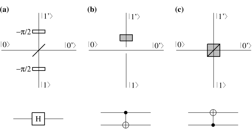
First, let us consider a single-photon experiment with a Mach-Zehnder interferometer in order to illustrate the optical simulation of elementary quantum gates (see Fig. 1). One qubit is involved in the description of the interferometer in terms of a quantum circuit: the “location” qubit, characterizing the information about “which path” is taken by the photon. Rather than using the occupation number representation for the photon, here we label the two input modes entering the beam splitter by and (“mode description” representation). The quantum state of the photon exiting the beam splitter then is or depending on the input mode of the photon. (The factor arises from the phase shift between the transmitted and the reflected wave in a lossless symmetric beam splitter [9].) This is the gate discussed earlier. Placing phase shifters at the input and output ports as shown in Fig. 1a, the beam splitter can be shown to perform a Hadamard transformation between input and output modes, i.e.,
| (1) |
In this sense, a lossless symmetric beam splitter (supplemented with two phase shifters) can be viewed as a Hadamard gate acting on a location qubit. Recombining the two beams using a second beam splitter in order to form a balanced Mach-Zehnder interferometer corresponds therefore, in this quantum circuit language, to having a second Hadamard gate acting subsequently on the qubit [10]. Since , it is not a surprise that the location qubit returns to the initial basis state ( or ) after two beam splitters. This simple quantum circuit (a sequence of two Hadamard gates) therefore describes the fact that the contributions of the two paths interfere destructively in one of the output ports, so that the photon always leaves the interferometer in the same direction as it entered.
More interestingly, consider now the same interferometer using polarized photons (the photon is horizontally polarized at the input). Assuming that none of the devices acts on polarization, the photon exits the interferometer with the same polarization. In a circuit language, this corresponds to introducing a “polarization” qubit ( stands for horizontal polarization) which remains in a product state with the location qubit throughout the circuit. If a polarization rotator is placed in one of the branches of the interferometer, flipping the polarization from horizontal to vertical , it is well known that interference disappears since both paths become distinguishable. This corresponds to placing a 2-bit controlled-not gate (represented in Fig. 1b) between the two Hadamard gates, where the location qubit is the control and polarization is the target bit. Conditional dynamics is achieved in the sense that the polarization of the photon is flipped conditionally on its location. The disappearance of interference then simply reflects the entanglement between location and polarization qubits (the reduced density matrix obtained by tracing over polarization shows that the photon ends up in is a mixed “location” state, i.e., it has a 50% chance of being detected in one or the other exit port). According to this, Feynman’s rule of thumb (namely that interference and which-path information are complementary) is a manifestation of the quantum no-cloning theorem: the location qubit cannot be “cloned” into a polarization qubit.
The optical equivalent of other basic quantum gates can be devised following the same lines. For example, a polarizing beam splitter achieves a controlled-not gate where the location qubit is flipped or not (the photon is reflected or not) conditionally on its state of polarization, as shown in Fig. 1c. Fredkin, Toffoli, as well as controlled-phase gates can easily be simulated in the same manner but will not be considered here. The central point is that, in principle, a universal quantum computation can be simulated using these optical substitutes for the universal quantum gates. The optical setup is constructed straightforwardly by inspection of the quantum circuit. A circuit involving qubits requires in general successive splitting stages of the incoming beam, that is, optical paths are obtained via beam splitters. (The use of polarization of the photon as a qubit allows using paths only.) This technique is thus limited to the simulation of quantum networks involving a relatively small number of qubits (say less than 5-6 with present technology). The key idea of a quantum computer, however, is to avoid just such an exponential size of the apparatus by having physical qubits performing unitary transformations in a -dimensional space. In this respect, it can be argued that an optical setup requiring optical elements to perform an -bit quantum computation represents a classical optical computer (see, e.g., [2]). Rather than debating this issue, our intention here is to show how to simulate small- quantum circuits using standard linear optics, which should prove to be useful for testing experimentally non-trivial quantum circuits or simple quantum algorithms.
Let us focus on the quantum circuit for teleportation [8] shown in Fig. 2. This circuit has the property that the arbitrary initial state of qubit is teleported to the state in which qubit is left after the process. In the original teleportation scheme [11], two classical bits (resulting from a Bell measurement) are sent by the emitter, while the receiver performs a specific unitary operation on depending on these two bits. However, it is shown in [8] that these unitary operations can be performed at the quantum level as well, by using quantum logic gates and postponing the measurement of the two bits to the end of the circuit. The resulting quantum circuit (Fig. 2) retains the essence of teleportation.

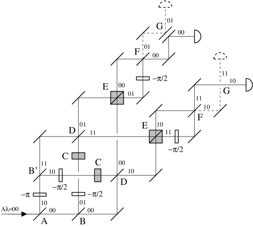
In our proposed optical realization of this circuit (see Fig. 3), qubits and correspond to the location of the photon at the first and second splitting level, while stands for the polarization qubit. Note that the photons are initially horizontally polarized, i.e., in polarization state . The first beam splitter A in Fig. 3 acts as a Hadamard gate on , as explained previously. For convenience, we depict the teleportation of state , so that the incident photon enters this beam splitter in the input port labeled . However, as any operation in can be realized optically, an arbitrary state of can be prepared (and then teleported) by having an initial beam splitter (with appropriate phase shifters) connected to both input ports of beam splitter A. The second level of beam splitters B (and B’ [12]) corresponds to the Hadamard gate B on in Fig. 2. The four paths at this point (, 01, 10, and 11) label the four components of the state vector characterizing qubits and . The probability amplitude for observing the photon in each of these four paths, given the fact the photon enters the port of beam splitters A and B, is then simply the corresponding component of the wave vector. The combined action of both controlled-not gates C in Fig. 2 is to flip the polarization state of the photon (qubit ) conditionally on the parity of (modulo 2), which is achieved by inserting polarization rotators C at the appropriate positions. In other words, the polarization is flipped on path 01 or 10, while it is unchanged on path 00 or 11.
The Hadamard gate D in Fig. 2 acts on qubit , independently of . This is achieved in Fig. 3 by grouping the paths in pairs with the same value of (i.e., crossing the paths) and using two beam splitters D in order to effect a Hadamard transformation on (one for each value of ). Similarly, the controlled-not gate E acting on (conditionally on the polarization) is simulated by the use of two polarizing beam splitters E after crossing the paths again [13]. The last Hadamard gate F in Fig. 2 corresponds to the two last beam splitters F, and the final controlled-not gate G is simply achieved by crossing the paths () in the lower arm () versus the upper arm (). In fact, the setup could be simplified by noting that the conditional crossing of paths achieved by G simply reduces to relabeling the output ports of beam splitter F in the arm. In Fig. 3, only those phase shifters associated with the Hadamard gates (Fig. 1a) are indicated that are relevant in the final detection.
The interpretation of this optical circuit in terms of teleportation is the following. After being “processed” in this quantum circuit, a photon which was initially horizontally polarized can reach one of the two “light” detectors (solid line in Fig. 3) with horizontal or vertical polarization. This corresponds to the final measurement of qubits and in Fig. 2, yielding two classical (random) bits: upper or lower arm, horizontal or vertical polarization. The third qubit, , contains the teleported quantum bit, that is, the initial arbitrary state of . Since the location state of the photon is initially in the setup represented in Fig. 3, it always exits to the “light” detector and never reaches the “dark” one (dashed line). For any measured value of (photon detected in the upper or lower arm) and (horizontally or vertically polarized photon), the entire setup forms a simple balanced Mach-Zehnder interferometer. Indeed, there are exactly two indistinguishable paths leading to each of the eight possible outcomes (four detectors, two polarizations); these interfere pairwise, just as in a standard Mach-Zehnder interferometer, explaining the fact that the photon always reaches the “light” detector (in both and arms and for both polarizations). In this sense, the initial “which-arm” qubit has been teleported to the final “which path” qubit . This process is formally equivalent to the original teleportation scheme [11] (although no classical bits are communicated) as exactly the same unitary transformations and quantum gates are involved. Note also that, as no photodetection coincidence is required in this optical experiment, the setup is actually not limited to single-photon interferometry. This largely simplifies the realization of the optical source since classical light fields (such as those from a laser) can be used rather than number states.
An actual experimental realization of the setup in Fig. 3 should be straightforward, if non-trivial. First, in order to avoid unwanted polarization effects at any of the mirrors and non-polarizing beam splitters, one would want to arrange the optics so that the various reflections occurred at near-normal incidence (thereby removing the distinction between s and p polarizations). The main difficulty in the setup is that various path lengths in the system should be the same. This could be achieved by adjusting for white-light fringes in each of the sub-interferometers (e.g., the Mach-Zehnder interferometer formed by the beam splitters A and lower D; the interferometer formed by the beam splitters B and upper E, etc.), without the additional phase shifters or polarization rotators. These latter elements could then be “added” by simply rotating appropriate birefringent wave plates already in the system. For example, an exact phase-shift is produced by simply rotating the slow axis of a half-wave retardation plate from horizontal to vertical [14]; a 90∘ polarization flip is caused by rotating a half-wave plate from horizontal to 45∘. When each of the subsystems is properly adjusted, and the extra phase and polarization-rotation elements correctly set, the entire system should perform as indicated, i.e., a photon incident from the left should only exit via the right-directed output ports. Finally, a tunable input (obtained with an additional beam splitter at the input) can be used to verify that any arbitrary state is faithfully teleported.
We have proposed a general technique for simulating small-scale quantum networks using optical setups composed of linear optical elements. This avoids the recourse to non-linear Kerr media to effect quantum conditional dynamics, a severe constraint in the usual optical realization of quantum circuits. A drawback of this technique is clearly the exponential increase of the resources (optical devices) with the size of the circuit. Nevertheless, as optical components that simulate 1- and 2-bit universal quantum gates can be cascaded straightforwardly, a non-trivial quantum computing optical device can be constructed if the number of component qubits is not too large. We believe this technique can be applied without fundamental difficulties to the encoding and decoding circuits that are involved in the simplest quantum error-correcting schemes [15], opening up the possibility for an experimental simulation of them.
This work was supported in part by NSF Grants PHY 94-12818 and PHY 94-20470, and by a grant from DARPA/ARO through the QUIC Program (#DAAH04-96-1-3086).
REFERENCES
- [1] D.P. DiVincenzo, Science 270, 255 (1995).
- [2] A. Barenco et al., Phys. Rev. A 52, 3457 (1995).
- [3] D.P. DiVincenzo, Phys. Rev. A 51, 1015 (1995); D. Deutsch, A. Barenco, and A. Ekert, Proc. R. Soc. London A 449, 669 (1995); S. Lloyd, Phys. Rev. Lett. 75, 346 (1995).
- [4] M. Reck, A. Zeilinger, H.J. Bernstein, and P. Bertani, Phys. Rev. Lett. 73, 58 (1994).
- [5] B. Yurke, S.L. McCall, and J.R. Klauder, Phys. Rev. A 33, 4033 (1986); S. Prasad, M.O. Scully, and W. Martienssen, Opt. Commun. 62, 139 (1987).
- [6] I.L. Chuang and Y. Yamamoto, Phys. Rev. A 52, 3489 (1995); Phys. Rev. Lett. 76, 4281 (1996).
- [7] G.J. Milburn, Phys. Rev. Lett. 62, 2124 (1989).
- [8] This teleportation circuit is equivalent to the one described in G. Brassard, S.L. Braunstein, and R. Cleve, submitted to Physica D.
- [9] V. Degiorgio, Am. J. Phys. 48, 81 (1980); A. Zeilinger, ibid. 49, 882 (1981); Z.Y. Ou and L. Mandel, ibid. 57, 66 (1989).
- [10] Here and below, it is understood that the path lengths are adjusted so that the difference between dynamical phases vanishes.
- [11] C.H. Bennett et al., Phys. Rev. Lett. 70, 1895 (1993).
- [12] For convenience, two realizations (B and B’) of the Hadamard gate are used in Fig. 3, where B’ is obtained from B by interchanging the and output ports in Fig. 1a.
- [13] A polarizing beam splitter leaves an horizontally polarized photon (in polarization state ) unchanged, while vertical polarization (state ) is reflected.
- [14] Phase shifts that occur after polarization transformations C (and which must therefore be independent of polarization) could be produced by a calibrated rotation of a thin glass plate.
- [15] L. Vaidman, L. Goldenberg, and S. Wiesner, Phys. Rev. A 54, R1745 (1996); S. L. Braunstein, Report No. quant-ph/9603024; R. Laflamme et al., Phys. Rev. Lett. 77, 198 (1996).