Low-Threshold Surface-Passivated Photonic Crystal Nanocavity Laser
Abstract
The efficiency and operating range of a photonic crystal laser is improved by passivating the InGaAs quantum well (QW) gain medium and GaAs membrane using an (NH4)S treatment. The passivated laser shows a four-fold reduction in nonradiative surface recombination rate, resulting in a four-fold reduction in lasing threshold. A three-level carrier dynamics model explains the results and shows that lasing threshold is as much determined by surface recombination losses as by the cavity quality factor (). Surface passivation therefore appears crucial in operating such lasers under practical conditions.
Photonic crystals (PCs) allow unprecedented control over the radiative properties of integrated emitters. By defining small mode-volume, high-quality factor () cavities in PCs, enhanced light-matter interaction becomes possible. This property has opened possibilities in fields including cavity quantum electrodynamics, detection, and light sources. Lasers in particular stand to gain through dramatically improved lasing threshold, modulation rate, cost, and large-scale device integration. From their first demonstrationPainter99science , PC lasers have most commonly relied on QWs for optical gain. However, QWs limit PC laser performance in many material systems because of large nonradiative (NR) surface recombination. This problem is particularly damaging in PC structures where embedded QWs expose a large surface area. Here we address the NR recombination problem by surface passivation. We show that (NH4)S-mediated surface passivation of PC laser structures lowers the NR recombination rate by more than and leads to reduction of lasing threshold. The increased efficiency extends the operating range from cryogenic to practical regimes, enabling room-temperature lasing at THz-modulation rates, as described in Englund2007APL_2 . A three-level rate equations model fits our experimental data well and suggests that surface passivation is crucial for PC lasers in InGaAs/GaAs and other material systems with fast NR surface recombination.
The PC nanocavity lasers consist of 172 nm-thick GaAs slabs patterned with 9x9 arrays of single-hole cavities defined in a square-lattice PC, similar to those described in Ref.Altug2006Nature . A central stack of four 8-nm In0.2Ga0.8As QWs, spaced by 8-nm GaAs barriers, forms the gain medium.
This sample is passivated using a solution of 7% (NH4)S in water. The treatment removes contamination and oxides from the GaAs and In0.2Ga0.8As surfaces and caps the fresh surface with sulfur atoms Oigawa1991JJAP . Samples were first cleaned in Leksol, acetone, and ethanol, then submerged in the (NH4)S solution for 15 minutes at 35∘C, and finally air-dried, following Ref.Petrovykh2002SS . We measured the radiative and NR properties, as well as lasing characteristics, before and after surface passivation.
Before presenting the experimental results, we describe the carrier dynamics at low temperature (K) using a three-level rate model. Letting represent the pump level carrier concentration (populated above the GaAs-bandgap using a laser with power ), the QW lasing level carrier concentration (resonant with the cavity frequency), and the coupled cavity photon density, we have111: pump active volume; : cavity angular frequency; : cavity ring-down time; : gain; : gain confinement factor for cavity mode with 8nm QWs; : pump energy absorption ratio; : SE lifetime in unpatterned QW; : NR lifetime in PC; : lifetimes of pump-level relaxation, SE, and NR transitions.
| (1) | |||||
In the center equation, the total lasing-level decay rate is separated into cavity decay, PC leaky-mode decay, and NR loss: . Here, expresses spontaneous emission (SE) rate quenching inside the PC bandgap compared to the SE rate in the bulk QW (following simulations in Englund05PRL ), while denotes the SE rate enhancement into the lasing mode.
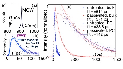
We estimate the lifetime constants in Eqs. 1 from time-resolved photoluminescence (PL) recorded with a streak camera (Hamamatsu N5716-03) in a confocal microscope setup 2007.OpEx.Englund . The measurements are performed separately on PC mirrors and bulk regions with 3.5 ps-long excitation pulses at 780 nm wavelength and 82 MHz repetition rate (Fig.1(b,c)). Samples were cooled to 10 K in a liquid-helium continuous-flow cryostat so that both unpassivated and passivated samples could be brought into lasing for comparison. From a fit of Eqs.1 to the rise-time of PL from the untreated sample, shown in Fig.1(b), we estimate the relaxation time from the pump level into the lasing level at 6 ps. The passivated sample also gives 6 ps.
Fig.1(c) shows the reduction in NR surface recombination after passivation: the PL decay lifetime from the PC mirror region is extended to ps from ps before passivation, while the decay lifetime from the bulk QW has nearly unchanged lifetime ps at 10W pump power. This data is analyzed using the bottom two equations of Eqs. 1 applied to PC and bulk regions, i.e., with denoting bulk or PC (). Assuming , the lifetime data then lets us estimate the unpatterned bulk SE lifetime 654 (605) ps and NR lifetime 35.5 (149) ps in the PC mirrors before (after) passivation. We assume equal NR lifetime across the cavity and surrounding PC mirrors since the diffusion length of rate-limiting holes m, greatly exceeding the cavity size.
To put this reduction in NR loss rate into perspective and compare it to reports on other types of structures, we extract the surface recombination velocity that describes the recombination at the QW surface. From the lifetime data in Fig.1(c), it is clear that most NR recombination results from the PC holes. The effect of passivation is therefore to reduce , and a simple model allows us to quantify by how much (pump power is small enough to neglect Auger recombination). The diffusion and recombination of the QW carrier concentration , uncoupled to the PC cavities, are described by the equation (following Hayes1988APL )
| (2) |
where is the ambipolar diffusion coefficient. Surface recombination enters through the boundary condition . Assuming isotropic minority-carrier density over the PC period nm, the total recombination rate of the PC depends only on the exposed QW surface area. This area is equal if the PC is replaced with an array of mesas whose radius equals the PC hole radius . Eq.2 is then easily solved in cylindrical coordinatesHayes1988APL , giving the total recombination rate , i.e., . We then find that cm/s ( cm/s) for the original (passivated) structure. This value for the surface recombination velocity is somewhat lower than previous room-temperature measurements on similar InGaAs/GaAs structures by Wenzel2004SST ; Hu1994JAP , which put it at between and cm/s. This is expected, since , the thermal velocity, which is smaller at 10K Sze1981 . Our observation of a four-fold lowering in with surface passivation is similar to other reports with (NH4)S Boroditsky2000JAP . However, better passivation results could probably be achieved with (NH4)Sx, , for which up to 50 improvement was reported Wenzel2004SST .
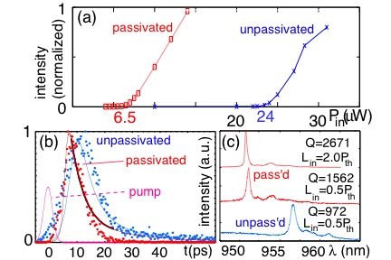
With this understanding of the carrier dynamics in the PC, we now consider the coupled cavity array laser. Microscope images show that only 7-9 cavities simultaneously lase in a single mode as fabrication inaccuracies lifted the cavity array’s resonance degeneracies. Fig.2(c) shows that the passivation treatment slightly blue-shifts the cavity resonance and raises by by cleaning and thinning the membrane, as observed in digital cavity etching Hennessy2005APL . The figure also shows the passivated structure when pumped above threshold; is then raised to due to gain. We estimate the average SE enhancement factor of emission coupled to the PC cavities from a lifetime measurement of the non-lasing cavity measured at lasing threshold, giving ps. The relation for the cavity-coupled SE rate,
| (3) |
gives .
Fig.2(a) shows the lasing curves for the original and passivated structures and indicates a four-fold reduction in threshold. This reduction in the pump power directly follows from Eqs. 1: for threshold, we solve Eqs. 1 in steady-state with (an average of one photon inside the resonant mode) and , the transparency carrier concentration where QW gain cancels absorption. Neglecting the slow pump-level radiative recombination , this gives
| (4) |
For typical parameters, cm-3 1995Coldren and , the first term in the brackets dominates. Within this term, the nonradiative part dominates the radiative one . Thus, in PC lasers using InGaAs QWs, or other gain media with similar surface recombination velocity, threshold is largely determined by NR recombination losses at the QW and GaAs membrane surfaces. After passivation, Eq.4 predicts a threshold reduction by factor 4.1 of the original value if the NR pump-level loss rate is assumed much smaller than the relaxation rate into the lasing level (otherwise an even larger reduction). We measured a decrease by factor , which is shows good agreement with the predicted value. The differential quantum efficiency, on the other hand, is nearly unaffected by the NR recombination rate, as can be easily derived from the rate equations (the physical reason is that once lasing begins, the stimulated emission rate is much faster than the NR loss rate.)
One of the most remarkable aspects of the PC nanocavity laser is the extremely fast modulation rate. In Fig.2(b), we present streak camera measurements of the lasing response to 3.4-ps-long pump pulses. The low-temperature measurements for the passivated and unpassivated samples were obtained at the same average pump power of 28 W (3.5 ps, 13 ns repetition), and the normalized lasing response is compared in the red and blue plots. After passivation, the laser responds somewhat faster with an exponential decay time of ps. We attribute this speed-up largely to relatively higher pump power above threshold (due to lower NR loss and higher cavity ). Faster time response is possible at higher pump power, as noted in Altug2006Nature . The rate model of Eqs.1 explains these time-response measurements well, as shown in the continuous-line fits.
In conclusion, we have demonstrated the threshold-lowering effect of surface-passivation treatment of InGaAs QWs in a PC coupled nanocavity array laser. The 4-fold reduction of NR surface recombination lowers the threshold pump power to 27% of its original value. Our three-level laser model agrees well with experimental observations and shows that NR recombination strongly affects lasing when the NR loss rate is faster than the modified SE rate in the PC. In this regime, reducing the NR surface recombination rate lowers the lasing threshold as much as lowering the cavity loss rate would, but has the advantage of not slowing lasing modulation rate. Using a carrier diffusion model, we calculate a drop in the QW surface recombination velocity from cm/s to cm/s after passivation; comparing this to literature, we believe that our results could be improved by applying better surface passivation techniques Wenzel2004SST ; Petrovykh2005 . The increased efficiency achieved in our lasers alleviates heating problems, which opens the door to room-temperature and CW operation Englund2007APL_2 and brings PC lasers closer to practical applications.
The authors thank Dr. D.Y. Petrovykh for his helpful comments. This work was supported by the MARCO IFC Center, NSF Grants ECS-0424080 and ECS-0421483, the MURI Center (ARO/DTO Program No.DAAD19-03-1-0199), as well as the NDSEG Fellowship (D.E.).
References
- (1) O. Painter, R.K. Lee, A. Scherer, A. Yariv, J.D. O’Brien, P.D. Dapkus, and I. Kim. Two-Dimensional Photonic Band-Gap Defect Mode Laser. Science, 284:1819–1821, June 1999.
- (2) D. Englund, H. Altug, and J. Vuckovic. Room-Temperature THz Photonic Crystal Nanocavity Array Laser. to be published in Appl. Phys. Lett., March 2007.
- (3) H. Altug, D. Englund, and J. Vučković. Ultrafast photonic crystal nanocavity laser. Nature Physics, 2:484–488, 2006.
- (4) H. Oigawa, J. F. Fan, Y. Nannichi, H. Sugahara, and M. Oshima. Universal Passivation Effect of (NH4)2Sx Treatment on the Surface of III-V Compound Semiconductors. Japanese Journal of Applied Physics, 30(3):322–325, March 1991.
- (5) D. Y. Petrovykh, M.J. Yang, and L.J. Whitman. Chemical and electronic properties of sulfur-passivated InAs surfaces . Surface Science, 523:231–240, 2002.
- (6) D. Englund, D. Fattal, E. Waks, G. Solomon, B. Zhang, T. Nakaoka, Y. Arakawa, Y. Yamamoto, and J. Vučković. Controlling the Spontaneous Emission Rate of Single Quantum Dots in a Two-Dimensional Photonic Crystal. Physical Review Letters, 95:013904, July 2005.
- (7) D. Englund, A. Faraon, B. Zhang, Y. Yamamoto, and J. Vuckovic. Generation and transfer of single photons on a photonic crystal chip. Optics Express, 15:5550–8, April 2007.
- (8) K. Tai, T. R. Hayes, S. L. McCall, and W. T. Tsang. Optical measurement of surface recombination in InGaAs quantum well mesa structures. Applied Physics Letters, 53(4):553, July 1988.
- (9) G. Beister and H. Wenzel. Comparison of surface and bulk contributions to non-radiative currents in InGaAs/AlGaAs laser diodes. Semiconductor Science and Technology, 19:494–500, 2004.
- (10) S. Y. Hu, S. W. Corzine, K.-K. Law, D. B. Young, A. C Gossard, and L. A. Coldren. Lateral carrier diffusion and surface recombination in InGaAs/AlGaAs quantum-well ridge-waveguide lasers. Journal of Applied Physics, 76(8):4479–87, 1994.
- (11) S. M. Sze. Physics of Semiconductor Devices, 2nd. ed. Wiley-Interscience, New York, 1981.
- (12) M. Boroditsky, I. Gontijo, M. Jackson, R. Vrijen, E. Yablonovitch, T. Krauss, C.-C. Cheng, A. Scherer, R. Bhat, and M. Krames. Surface recombination measurements on III-V candidate materials for nanostructure light-emitting diodes . Journal of Applied Physics, 87(7):3497–3504, April 2000.
- (13) K. Hennessy, A. Badolato, A. Tamboli, P. Petroff, E. Hu, M. Atature, J. Dreiser, and A.Imamoǧlu. Tuning photonic crystal nanocavity modes by wet chemical digital etching. Applied Physics Letters, 87:021108–1, May 2005.
- (14) L. A. Coldren and S. W. Corzine. Diode Lasers and Photonic Integrated Circuits. New York: Wiley, 1995.
- (15) D. Y. Petrovykh, J. P. Long, and L. J. Whitman. Surface passivation of InAs(001) with thioacetamide. Applied Physics Letters, 86:242105, 2005.