Cluster state quantum computation in coupled cavity arrays
Abstract
Measurement-based quantum computation has revolutionized quantum information processing, and the physical systems with which it can be implemented. One simply needs the ability to prepare a particular state, known as the cluster state, and subsequently to perform single-qubit measurements on it. Nevertheless, a scalable implementation is yet to be realized. Here we propose a hybrid light-matter system comprised of coupled cavities interacting with two level systems. Utilising the stable, individually addressable, qubits resulting from the localised long-lived atom-photon excitations, we demonstrate how to use the natural system dynamics to ‘weave’ these qubits into a cluster state and propose the implementation of quantum algorithms employing just two rows of qubits. Finally, we briefly discuss the prospects for experimental implementation using atoms, quantum dots or Cooper pair boxes.
Quantum computation on cluster states cluster1 has been proposed in a variety of systems, including linear optics, quantum dots, neutral atoms in optical lattices, and flying atom schemes nielsen:040503 ; browne-2005-95 ; kok:04 ; lim-2005-95 ; benjamin-2005-7 ; borhani-2005-71 ; Kay:2005a ; blythe-varcoe ; schon . To date, experiments have been performed using optical lattices Greiner:2003a , where the cluster state can be created, but the current lack of individual addressing remains the stumbling block and linear optics Walther ; Pan , where scalability remains a problem due to the need to generate the initial many-photon state from, for example, high orders of the parametric down conversion proecss. On the other hand, there have recently been theoretical and experimental breakthroughs into the possibility of direct coupling of high Q cavities and in achieving strong coupling between the cavity mode and an embedded two-level system. A variety of technologies have been employed, namely fiber coupled micro-toroidal cavities interacting with atoms aoki-2006 ; armani-vahala03 , arrays of defects in photonic band gap materials (PBGs) vuckovic-apl ; song-noda05 ; AntonioBadolato05202005 and superconducting qubits coupled through microwave stripline resonators wallraff-2004 . This has prompted proposals for the implementation of optical quantum computing angelakis-ekert04 , the production of entangled photons angelakis-bose06 and the realization of Mott insulating and superfluid phases angelakis-bose06b ; hartmann-2006-2 ; greentree-2006 . Here we propose the use of such arrays for the realization of cluster state quantum computation.
System Description: We start be describing the system and showing how to construct qubits from the hybrid light-matter excitations (polaritons). For simplicity, we describe the system as a linear chain of coupled cavities doped with two level systems, although this is readily adapted to the two-dimensional setting that we require. and are the atomic ground and excited states at site (we henceforth use the term ‘atom’ to refer to any relevant two level system). The Hamiltonian describing the system is the sum of three terms; is the Hamiltonian for the free light and dopant parts, the Hamiltonian describing the internal coupling of the photon and dopant in a specific cavity and for the light hopping between cavities.
| (1) | |||||
| (2) | |||||
| (3) |
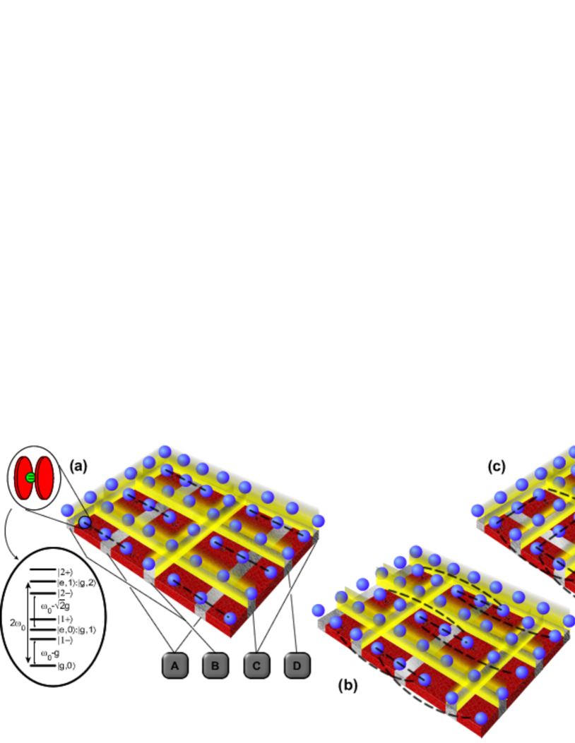
and are the photon frequencies and hopping rates respectively and g is the light-atom coupling strength. The component of the Hamiltonian can be diagonalized in a basis of combined photonic and atomic excitations, called polaritons (Fig. 1). These polaritons are defined by creation operators , where the polaritons of the th atom-cavity system are given by with energies , and denotes the -photon Fock state. As has been shown elsewhere, a polaritonic Mott phase exists in this system where a maximum of one excitation per site is allowed angelakis-bose06b . This originates from the repulsion due to the photon blockade effect PhysRevLett.79.1467 ; birnbaum-2005 . In this Mott phase, the system’s Hamiltonian can be written in the interaction picture as where (Fig. 1). As double or more occupancy of the sites is prohibited, one can identify with , where and are the standard Pauli operators. The system’s Hamiltonian then becomes the standard XY model of interacting spin qubits with spin up/down corresponding to the presence/absence of a polariton.
| (4) |
Some applications of XY spin chains in quantum information processing can thus been implemented in this system bose .
Cluster state generation: The typical implementation of cluster state quantum computing requires initializing all qubits in a 2D lattice in the state and then performing controlled-phase gates () between all nearest-neighbours. In the present system, we have no direct two-qubit gate and the available interaction is not of the Ising type, which straightforwardly gives controlled-phase gates cluster1 , but an ‘always on’ global Hamiltonian coupling of the XY form. It behooves us to consider how we will proceed with the measurement sequence once the cluster state has been generated without the system continuing to evolve. (The need to disable the evolution is an aspect often neglected when discussing the generation of cluster states, either as the ground states of ‘natural’ Hamiltonians rudolph:06 , or from evolution of the Ising Hamiltonian). This requirement can be realized by combining the system’s natural dynamics with a protocol where some of the available physical qubits are used as gate “mediators” and the rest as the logical qubits. The mediator atoms can be Stark shifted on and off resonance from their cavities through the application of an external field, inhibiting the photon hopping and thereby isolating each logical qubit. The same inhibition of couplings will be used to generate the cluster state. We note here that the error introduced in the step is due to a second-order transition between on-resonance qubits (via a dark-passage through the central off-resonant qubit), which is thus supressed by a factor of order , where is the detuning of the off-resonant cavity.
Before describing the 4-step global gate sequence to create the cluster state, first observe that for the control phase part is enough to localize chains of 3 qubits, let them evolve for a time and then apply a measurement on the middle ‘mediator’ qubit (in the basis). Depending on the measurement result, or , a nonlocal gate is generated between the remaining two qubits, either SWAP. or SWAP. respectivelyyung-2004-4 ; Christandl:2004a . In both cases, the gates in addition to the are Clifford operations which can be recorded and taken into account during the measurement-based computation.
Our sequence to generate the cluster state initiates by preparing all qubits in the state through the application of global pulse. One quarter of the sites will be used as logical qubits and the rest as “mediators” and “off” qubits interchangeably. All qubits addressed by the gates A to D (Fig. 1) are, by default, “off”, thereby isolating all the qubits. Switching on any one of the four gates thus creates chains of 3 qubits, which we use to enact a between pairs of qubits (separated by a mediator qubit, which was previously off). Consecutive use of each of the gates A to D serves to enact a gate between a particular qubit and all of its nearest-neighbours, and this happens in parallel across the whole device. This entire sequence is illustrated in Supplementary Video 1. The measurement sequence is then applied as requested by the cluster state algorithm, utilizing the local accessibility of the sites (in any implementation, the cavity-atom systems are well separated compared to the resolution of the external field used for addressing them) aoki-2006 ; armani-vahala03 ; vuckovic-apl ; song-noda05 ; AntonioBadolato05202005 ; wallraff-2004 .
In Fig. 2, we calculate the fidelity of generation of a cluster state on a 3x3 array of cavities. More sophisticated schemes have the potential to further reduce the experimental errors. For example, standard Hamiltonian simulation techniques allow us to negate the second order exchange term due to the off-resonance cavities, simply by repeatedly applying gates to every second on-resonance triplet throughout the evolution. One might even hope that we could use this coherent effect to enhance the scheme through the use of, for example, optimal control techniques.
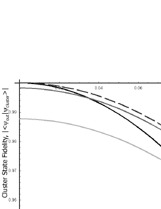
Most of the errors considered here (cavity leakage, spontaneous emission of the atom, and on-off detuning of qubits) are local effects, introducing local noise, which can ultimately be addressed by fault-tolerant techniques raussendorf .
Implementing algorithms: Initial experimental algorithmic implementations with coupled cavities can be expected to utilize the most basic building block of our scheme, a grid of cavities, which allows us to generate a four-qubit cluster state. As with the four-photon cluster state recently used by Walther et al. Walther , this cluster state would be suitable for demonstrating the preparation of an arbitrary one-qubit state, an entangling gate between two qubits, and even the implementation of Grover’s search algorithm on two qubits Walther . For example, by applying the local gates , where is the Hadamard rotation, we convert of ‘box’ cluster that the grid prepares into the 1D cluster state of 4 qubits, which is given the interpretation of a single qubit, and measurements on the state yield quantum gates on this single qubit. Moreover, generation of this four qubit cluster state is simpler than generation of an arbitrarily sized cluster state because we only need two control steps instead of four, thereby keeping us even further within the decoherence time of the system.
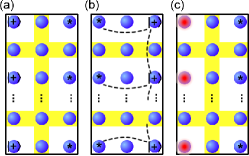
Perhaps the next important step would then be to demonstrate Shor’s factoring algorithm, the factoring of 15 being the standard demonstration. To implement as a cluster state computation, the six computational qubits shor_imp translate into the requirement of a cluster state that is eleven qubits wide. Hence, we need an array which is 21 cavities wide. The breadth of the cluster state, which corresponds to time in the circuit model, is a quantity that we can trade against the time taken for the computation. At one extreme, we can create the whole cluster state in one go, with the simple set of four steps already outlined, and we benefit from the large degree of parallelism available to us. This requires a 2D grid of cavities of size 111To arrive at this required number of gates, we have taken the circuit presented in shor_imp and converted it into a nearest-neighbor, 2-qubit gate algorithm. Hence, the possibility for some small degree of optimisation in the number of qubits remains.. At the other extreme, a grid of cavities suffices. In this case, one starts with the cluster state, and performs one time step of measurement (i.e. measure the 11 qubits in one column). The result remains in the other column. We then repeat the cluster state generation process, reinitialising the measured qubits in the cluster state, and performing the next time step (Fig. 3). This requires 156 consecutive entangling steps, but the reinitialising of the cluster state after measurement eliminates the effect of decoherence over this timescale. Any combination between these two extremes is also possible, and is a necessary property of any scalable implementation of cluster state computation for the sake of preventing decoherence.
Once initial cluster state experiments have been performed, it simply becomes a question of how many cavities one can reasonably couple together. Alternatively, since the two-qubit gate that we can generate is entangling (and hence universal for quantum computation), we can also consider using it directly to implement the circuit model of computation. This has a much smaller overhead of qubits, but instead requires much higher quality cavities. For example, to factor 15 we would only need a grid of cavities to give us six computational qubits. However, we would need approximately 15 consecutive entangling steps (we have attempted to minimise this number by allowing as many of the gates to be applied in parallel as possible, and by optimising the initial labelling of each qubit), hence requiring a time of order . Hence, to reduce the effect of dissipative decay, we require an order of magnitude improvement in the decoherence properties of the qubits to compensate for the increased running time.
Experimental implementations: As previously mentioned, there are three primary candidate technologies; fiber coupled micro-toroidal cavities aoki-2006 ; armani-vahala03 , arrays of defects in PBGs vuckovic-apl ; song-noda05 ; AntonioBadolato05202005 and superconducting qubits coupled through microwave stripline resonators wallraff-2004 . In order to achieve the required limit of no more than one excitation per site angelakis-bose06b , the ratio between the internal atom-photon coupling and the hopping of photons down the chain should be of the order of ( can be tuned while fabricating the array by adjusting the distance between the cavities and g depends on the type of the dopant). In addition, the cavity/atomic frequencies to internal coupling ratio should be and the losses should also be small, , where and are cavity and atom/other qubit decay rates. The polaritonic states under consideration are essentially unaffected by decay for a time (ns for the toroidal case and ns for microwave stripline resonators). While the decay time of may seem uncomfortably close to the preparation time for a cluster state, , the previously described technique (Fig. 3) of continuously reforming the cluster state and connecting it to the output of the previous stage allows a continuous computation that exceeds the decay time for an individual cavity. The required parameter values are currently on the verge of being realised in both toroidal microcavity systems with atoms and stripline microwave resonators coupled to superconducting qubits, but further progress is needed. Arrays of defects in PBGs remain one or two orders of magnitude away, but recent developments, and the integrability of these devices with optoelectronics, make this technology very promising as well. In all implementations the cavity systems are well separated by many times the corresponding wavelength of any local field that needs to be applied in the system for the measurement process.
Conclusions: In this paper, we have shown how universal quantum computation could be realized in a coupled array of individually addressable atom-cavity systems, where the qubits are given by mixed light-matter excitations in each cavity site. While single-qubit operations can be locally achieved, the only available interaction between qubits is due to the natural system Hamiltonian. We show how to manipulate this to give a controlled-phase gate between pairs of qubits. This allows computation either using the circuit model, or a measurement-based computation, the latter being most suited to reducing experimental errors. We have discussed possible architectures for implementing these ideas using photonic crystals, toroidal microcavities and superconducting qubits and point out their feasibility and scalability with current or near-future technology.
This work was supported by the QIP IRC (GR/S821176/01), Clare College Cambridge and the European Union through the Integrated Projects QAP (IST-3-015848), SCALA (CT-015714) and SECOQC.
References
- (1) Raussendorf, R. & Briegel, H. J., Phys. Rev. Lett. 86, 5188 (2001).
- (2) Nielsen, M. A., Phys. Rev. Lett. 93, 040503 (2004).
- (3) Browne, D. E. & Rudolph, T., Phys. Rev. Lett. 95, 010501 (2005).
- (4) Barrett, S. D. & Kok, P., Phys. Rev. A 71, 060310(R) (2005).
- (5) Lim, Y., Beige, A. & Kwek, L., Phys. Rev. Lett. 95, 030505 (2005).
- (6) Benjamin, S. C., Eisert, J. & Stace, T. M., New J. Phys. 7, 194 (2005).
- (7) Borhani, M. & Loss, D., Phys. Rev. A 71, 034308 (2005).
- (8) A. Kay, J. K. Pachos & C. S. Adams, Phys. Rev. A 73, 022310 (2006).
- (9) Blythe P.J. & Varcoe B.T. H, New J. of Phys. 8, 231 (2006).
- (10) Schön C. et al.,, Phys. Rev. Lett. 11, 110503 (2005).
- (11) Mandel, O. et al., Nature 425, 937 (2003).
- (12) Walther, P. et al., Nature 434, 169 (2005).
- (13) Pan, J-W. et al., Nature Physics 3, 91 (2007).
- (14) Armani, D. K., Kippenberg, T. J., Spillane, S. M. & Vahala, K. J., Nature 421, 925 (2003).
- (15) Aoki, T. et al., Nature 443, 671 (2006).
- (16) Hattice, A., & Vuckovic, J., Appl. Phys. Lett. 84, 191 (2004)
- (17) Song, B.-S., Noda, S., Asano, T. & Akahane, Y., Nat. Mater. 4, 207-210 (2005)
- (18) Badolato, A. et al., Science 308, 1158–1161 (2005).
- (19) Wallraff, A. et al., Nature 431, 162 (2004).
- (20) Angelakis, D. G., Santos, M. F., Yannopapas, V. & Ekert, A., Phys. Lett. A 362, 377 (2007).
- (21) Angelakis, D. G. & Bose, S., J. Opt. Soc. Am. B 24, 266 (2007).
- (22) Angelakis, D. G., Santos, M. F. & Bose, S., Photon blockade induced mott transitions and XY spin models in coupled cavity arrays (2006), quant-ph/0606159.
- (23) Hartmann, M. J., Brandao, F. G. S. L. & Plenio, M. B., Nat. Phys. 2, 849 (2006).
- (24) Greentree, A. D., Tahan, C., Cole, J. H. & Hollenberg, L. C. L., Nat. Phys. 2, 856 (2006).
- (25) Imamoḡlu, A., Schmidt, H., Woods, G. & Deutsch, M., Phys. Rev. Lett. 79, 1467–1470 (1997).
- (26) Birnbaum, K. M. et al., Nature 436, 87 (2005).
- (27) Bose, S., Phys. Rev. Lett. 91, 207901 (2003).
- (28) Bartlett, S. D. & Rudolph, T., Phys. Rev. A 74, 040302(R) (2006).
- (29) Yung, M.-H., Leung, D. W. & Bose, S., Quant. Infor. and Comp. 4, 174 (2004).
- (30) Albanese, C., Christandl, M., Datta, N. & Ekert, A., Phys. Rev. Lett 93, 230502 (2004).
- (31) Raussendorf, R., Harrington, J. & Goyal, K., New J. Phys. 9, 199 (2007).
- (32) Kieling, K., Gross, D. & Eisert, J., J. Opt. Soc. Am. B 24(2), 184 (2007).
- (33) Lieven, M. K. et al., Nature 414, 883 (2001).