An all-optical trap for a gram-scale mirror
Abstract
We report on a stable optical trap suitable for a macroscopic mirror, wherein the dynamics of the mirror are fully dominated by radiation pressure. The technique employs two frequency-offset laser fields to simultaneously create a stiff optical restoring force and a viscous optical damping force. We show how these forces may be used to optically trap a free mass without introducing thermal noise; and we demonstrate the technique experimentally with a 1 gram mirror. The observed optical spring has an inferred Young’s modulus of 1.2 TPa, 20% stiffer than diamond. The trap is intrinsically cold and reaches an effective temperature of 0.8 K, limited by technical noise in our apparatus.
pacs:
03.65.-w, 42.50.Vk, 42.50.Xa, 04.80.Nn, 07.10.CmThe change in dynamics caused by radiation pressure effects has been explored in many mechanical systems; its proposed applications include cooling toward the ground state of nano- or micro-electromechanical systems (N/MEMS) Karrai ; schwabNature2006 ; zeilingerNature2006 ; klecknerNature2006 ; arcizetNature2006 ; vahala , enhancing the sensitivity of gravitational wave (GW) detectors BC3 ; 40mOS , and generation of ponderomotively squeezed light corbittPRA2006 . Two types of radiation pressure effects are evident in these systems: the optical restoring and viscous damping forces, both of which are generated by detuned optical cavities. Detuning a cavity to higher frequencies (blue-detuning) gives rise to a restoring force, known as an optical spring BCcontrols ; msupla2002os ; Sheard , as well as an anti-damping force due to the delay in the cavity response time. Conversely, detuning to lower frequencies (red-detuning) gives rise to optical damping manciniPRL1998 along with an anti-restoring force.
In N/MEMS, optical (anti-)restoring forces are typically negligible in comparison to the stiff mechanical suspension. However, optical damping produces cooling in a red-detuned cavity, while anti-damping heats, or even leads to instability in a blue-detuned cavity cohadonPRL1999 ; Karrai ; bouwmeesterPRL2006 ; schwabNature2006 ; zeilingerNature2006 ; klecknerNature2006 ; arcizetNature2006 . In GW detectors, on the other hand, the optical spring force may dominate, since the mechanical suspension of their mirrors is very soft. The typical use of the optical spring effect in these systems is to enhance the sensitivity of the detector around the optical spring resonance. To achieve a restoring force, the cavity must be blue-detuned, and the coincident optical anti-damping force can both destabilize the cavity and give rise to parametric instabilities of the internal modes of its mirrors corbittPIOS ; 40mOS ; kippenbergPRL2005 . In general, whenever the radiation pressure of a single optical field dominates both the mechanical damping and restoring forces, the system is unstable due to the presence of a strong anti-damping or anti-restoring optical force. Hence, until now this regime has been achieved only with the help of active feedback control to stabilize the dynamics corbittPIOS ; 40mOS .
Here we propose and demonstrate a technique that circumvents the optomechanical instability by using the radiation pressure of a second optical field, thus creating a stable optical trap for a 1 gram mirror. This opens a new route to mitigating parametric instabilities in GW detectors, and probing for quantum effects in macroscopic objects.
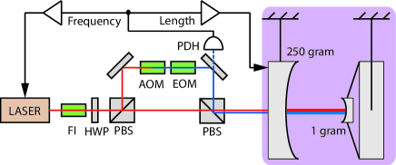
The experiment shown schematically in Fig. 1 was performed to demonstrate the optical trapping scheme. The gram input mirror of the m long cavity is suspended as a pendulum with oscillation frequency of Hz for the longitudinal mode. The gram end mirror is suspended by two optical fibers in diameter, giving a natural frequency Hz for its mechanical mode, with quality factor . On resonance, the intracavity power is enhanced relative to the incoming power by a resonant gain factor , where is the transmission of the input mirror, and the resonant linewidth (HWHM) is kHz.
If the resonance condition is exactly satisfied, the intracavity power depends quadratically on small changes in the length of the cavity. In this case the radiation pressure is only a second-order effect for the dynamics of the cavity. The constant (dc) radiation pressure is balanced through external forces; consequently, only fluctuations of the radiation pressure are considered here. If the cavity is detuned from the resonance condition, the intracavity power, and therefore the radiation pressure exerted on the mirrors, becomes linearly dependent on the length of the cavity, analogous to a spring. The resulting spring constant is given in the frequency domain by corbittPIOS ; msupla2002os
| (1) |
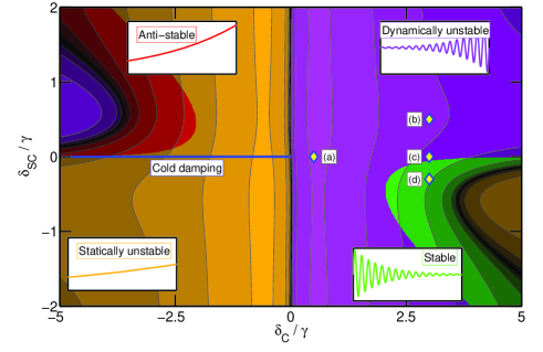
where is the frequency of the motion, and and are the detuning and input power of the laser, respectively. Note the dependence of on the sign of . For (in our convention), corresponds to a restoring force, while gives an anti-restoring force; we do not explore this regime experimentally since it is always unstable for our system (see Fig. 2). The light in the cavity (for ) responds to mirror motion on a time scale given by . This delay has two effects. First, for high frequency motion (), the response of the cavity, and the corresponding radiation pressure, are reduced, and we see from Eq. (An all-optical trap for a gram-scale mirror) that . Second, the response of the cavity lags the motion, leading to an additional force proportional to the velocity of the mirror motion — a viscous force with damping coefficient given by corbittPIOS ; msupla2002os
| (2) |
where is the reduced mass of the two mirrors. Because the cavity response lags the motion of the mirrors, a restoring spring constant implies a negative damping. Again we see that when both optical forces dominate their mechanical counterparts, the system must be unstable.
To stabilize the system we use two optical fields that respond on different time scales. One field should respond quickly, so that it makes a strong restoring force and only a weak anti-damping force. The other field should respond slowly, so that it creates a strong damping force, with only a minor anti-restoring force. This could be achieved with two cavities of differing bandwidths that share a common end mirror. However, it is simpler to use a single cavity and two fields with vastly different detunings. From Eqs. (An all-optical trap for a gram-scale mirror) and (2), taking (valid at the optical spring resonant frequency), we find
| (3) |
we see that an optical field with larger detuning has less damping per stiffness. The physical mechanism for this is that at larger detunings, the optical field resonates less strongly than for smaller detunings, so the time scale for the cavity response is shorter, leading to smaller optical damping. To create a stable system, we consider a carrier field (C) with large detuning that creates a restoring force, but also a small anti-damping force. To counteract the anti-damping, a strong damping force is created by injecting a subcarrier (SC) with small detuning . For properly chosen power levels in each field, the resulting system is stable; we found a factor of 20 higher power in the carrier to be suitable in this case. To illustrate the behavior of the system at all detunings, the various stability regions are shown in Fig. 2 for this fixed power ratio. Point (d) in particular shows that the system is stable for our chosen parameters.
Next we highlight some notable features of this optical trapping technique that were demonstrated experimentally using the apparatus of Fig. 1.
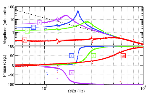
(i) Extreme rigidity: With no SC detuning and , the Hz mechanical resonance of the gram mirror oscillator was shifted as high as kHz (curve (a) in Fig. 3), corresponding to an optical rigidity of N/m. To put this number into perspective, consider replacing the optical mode with a rigid beam with Young’s modulus . The effective Young’s modulus of this mode with area of the beam spot () and length m of the cavity, is given by TPa, stiffer than any known material (but also with very small breaking strength). Such rigidity is required to operate the cavity without external control; ambient motion would otherwise disrupt the cavity resonance condition.
(ii) Stabilization: Also shown in Fig. 3 are curves corresponding to various C and SC detunings. In curves (b), (c) and (d), we detune the carrier by more than the cavity linewidth since the optical spring is less unstable for large . With no SC detuning, the optomechanical resonant frequency reaches Hz, shown in curve (c). Note that the optical spring is unstable, as evidenced by the phase increase of about the resonance (corresponding to anti-damping). Next we detune the subcarrier in the same direction as the carrier, shown in curve (b), which increases the resonant frequency and also increases the anti-damping, demonstrated by the broadening of the resonant peak. For these two cases, electronic servo control is used to keep the cavity locked. If the control system is disabled, the amplitude of the cavity field and mirror oscillations grow exponentially. Remarkably, when the subcarrier is detuned in the opposite direction from the carrier, the optical spring resonance becomes stable, shown in curve (d), allowing operation of the cavity without electronic feedback at frequencies above 30 Hz; we note the change in phase behavior and the reduction of the resonant frequency. This shows how the frequency and damping of the optical spring can be independently controlled in the strong coupling regime.
(iii) Optical cooling: The thermal excitation spectrum of the mirror, given by , is not changed by the optical forces. It is informative to express this in terms of the optomechanical parameters , and an effective temperature, , such that the form of the equation is maintained. The effective temperature thus is given by
| (4) |
where () is the quality factor of the oscillator. In the standard cold damping technique lower is achieved by decreasing via the viscous radiation pressure damping. The optical spring effect results in further cooling by increasing the resonant frequency. The combination of both effects allows for much colder temperatures to be attained than with cold damping alone. This is relevant to experiments hoping to observe quantum effects in macroscopic objects, since it greatly reduces the thermal occupation number
| (5) |
both by decreasing the effective temperature, and increasing the resonant frequency.
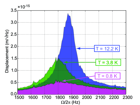
In the current experiment the displacement spectrum is dominated by laser frequency noise at . We can nonetheless estimate the effective temperature of the optomechanical mode by measuring the displacement of the mirror, and equating , where is the RMS motion of the mirror. To determine in our experiment, we measure the noise spectral density of the error signal from the cavity, calibrated by injecting a frequency modulation of known amplitude at 12 kHz. The displacement noise measured in this way is shown in Fig. 4. The lowest measured temperature of K corresponds to a reduction in by a factor of .
In conclusion, we have exhibited a scheme that uses both the optical spring effect and optical damping from two laser fields to create a stable optomechanical system in which the dynamics are determined by radiation pressure alone. We experimentally demonstrated that the system is indeed stable, confirmed by deactivating the electronic control system and permitting the cavity to evolve freely at the dynamically relevant frequencies. We believe this is a useful technique for manipulating the dynamics of radiation pressure dominated systems, to quell their instabilities and examine their quantum behavior free from external control.
We would like to thank our colleagues at the LIGO Laboratory and the MQM group, and also Steve Girvin; a casual discussion with Steve prompted some of the experimental work explored in this manuscript. We are also grateful to Mike Boyle for first prompting us to explore double optical springs, and to Kentaro Somiya for helpful discussions and introduction to the MQM group. We gratefully acknowledge support from National Science Foundation grants PHY-0107417 and PHY-0457264. Y.C.’s research was supported by the Alexander von Humboldt Foundation’s Sofja Kovalevskaja Award (funded by the German Federal Ministry of Education and Research).
References
- (1) C. H. Metzger, K. Karrai, Nature 432, 1002 (2004).
- (2) A. Naik, O. Buu, M. D. LaHaye, A. D. Armour, A. A. Clerk, M. P. Blencowe, and K. C. Schwab, Nature443,193 (2006).
- (3) S. Gigan, H. Böhm, M. Paternostro, F. Blaser, G. Langer, J. Hertzberg, K. Schwab, D. Bäuerle, M. Aspelmeyer, and A. Zeilinger, Nature 444, 67 (2006).
- (4) D. Kleckner, D. Bouwmeester, Nature 444, 75 (2006).
- (5) O. Arcizet, P.-F. Cohadon, T. Briant, M. Pinard, and A. Heidmann, Nature 444, 71 (2006).
- (6) A. Schliesser, P. Del’Haye, N. Nooshi, K. J. Vahala, and T. J. Kippenberg, Phys. Rev. Lett. 97, 243905 (2006).
- (7) A. Buonanno and Y. Chen, Phys. Rev. D 65, 042001 (2002).
- (8) O. Miyakawa, R. Ward, R. Adhikari, M. Evans, B. Abbott, R. Bork, D. Busby, J. Heefner, A. Ivanov, M. Smith, R. Taylor, S. Vass, A. Weinstein, M. Varvella, S. Kawamura, F. Kawazoe, S. Sakata, and C. Mow-Lowry, Phys. Rev. D 74, 022001 (2006).
- (9) T. Corbitt, Y. Chen, F. Khalili, D. Ottaway, S. Vyatchanin, S. Whitcomb and N. Mavalvala, Phys. Rev. A 73, 023801 (2006).
- (10) A. Buonanno, Y. Chen, Phys. Rev. D 65, 042001 (2002).
- (11) V. B. Braginsky, S. P. Vyatchanin, Phys. Lett. A 293, 228 (2002).
- (12) B. S. Sheard, M. B. Gray, C. M. Mow-Lowry, D. E. McClelland and S. E. Whitcomb, Phys. Rev. A, 69, 051801 (2004).
- (13) S. Mancini, D. Vitali, P. Tombesi, Phys. Rev. Lett 80, 688 (1998).
- (14) D. Kleckner, W. Marshall, M. de Dood, K. Dinyari, B-J. Pors, W. Irvine, and D. Bouwmeester, Phys. Rev. Lett 96, 173901 (2006).
- (15) P. F. Cohadon, A. Heidmann, M. Pinard, Phys. Rev. Lett. 83, 3174 (1999).
- (16) T. Corbitt, D. Ottaway, E. Innerhofer, J. Pelc, N. Mavalvala, Phys. Rev. A 74, 021802 (2006).
- (17) T. J. Kippenberg, H. Rokhsari, T. Carmon, A. Scherer and K. J. Vahala, Phys. Rev. Lett, 95, 033901 (2005).