A photon loss tolerant Zeno CSIGN gate
Abstract
We model an optical implementation of a csign gate that makes use of the Quantum Zeno effect Franson et al. (2004); Franson and Hendrickson (2006) in the presence of photon loss. The raw operation of the gate is severely affected by this type of loss. However, we show that by using the same photon loss codes that have been proposed for linear optical quantum computation (LOQC), the performance is greatly enhanced and such gates can outperform LOQC equivalents. The technique can be applied to other types of nonlinearities, making the implementation of nonlinear optical gates much more attractive.
pacs:
03.67.Lx, 03.67.PpEncoding information on optical qubits is a promising route to quantum information processing. In particular, by encoding the information in polarisation at optical frequencies, a photon experiences essentially no coupling to the environment in free space, but still can be manipulated easily with passive linear optical devices.
This strength of optical systems is also their weakness. Very weak coupling to the environment means that it is also very difficult to get photonic qubits to interact. Linear optical quantum computation (LOQC) Kok et al. (2005) is the most developed scheme for optical quantum information processing, and it sidesteps the interaction issue by using non-deterministic gates, conditioned on photo-detection results. The inherent nondeterminism in LOQC is hidden by making use of teleportation and encoding. Though scalable in principle, such an approach takes a heavy penalty in resources.
An alternative approach was recently proposed by Franson and co-workers Franson et al. (2004); Franson and Hendrickson (2006) for constructing an entangling gate. In this proposal, two photonic qubits interact via evanescent coupling of the modes between two fibre cores. Unwanted two photon terms are suppressed via the Quantum Zeno effect Misra and Sudarshan (1977) provided by strong two-photon absorption within the fibre cores. A key question for the implementation of this gate is the effect of single photon loss on it’s function. Recent estimates Franson and Hendrickson (2006) suggest that with appropriate engineering, the rate of two photon absorption may be set four or five orders of magnitude larger than single photon loss. Given such a large ratio of absorption rates, how does the gate perform? Since manipulating the polarisation state of a single photon can be currently achieved with high fidelity, the addition of an efficient entangling gate would be a tremendous boost to optical quantum computation.
In this paper we evaluate a csign gate constructed using the Quantum Zeno technique in the presence of photon loss — a dominant decoherence process in optical systems. We model the gate by solving the master equation evolution for the system, characterising the effect of the photon loss by calculating the closeness of the gate to an ideal csign gate. Finally, we propose using some of the encoding protocols that have been developed for LOQC to mitigate the effect of this loss.
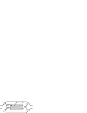
A stylised representation of the gate is given in Fig. 1. The inner part of the gate (within the dashed rectangle in the figure) acts as a csign on ‘single-rail’ qubits, that is, on qubits where a logical is encoded as a vacuum state and a logical as a single Fock state. The two qubits interact with a strength within the nonlinear region depicted, for a time , and also undergo one- and two-photon loss at rates and , respectively. Note that at most there will be two photons within the gate corresponding to the term.
Since the ideal csign gate only changes the phase of the qubits and not the photon number, the same gate can be used for ‘dual-rail’ encoded qubits. In dual-rail encoding there is one photon encoded in two modes, such as with polarisation encoding where and , and the latter kets are Fock-state occupation numbers. The gate can be applied to the polarisation encoded qubits also as depicted in Fig. 1. The polarisation modes are spatially split by a polarising beamsplitter and only the mode from each qubit goes through the device which acts as a single-rail device for those modes, only the term should acquire a phase-shift. The polarisation modes are recombined after the device.
The interaction between the two modes is described by the interaction Hamiltonian for a beamsplitter where , are the bosonic creation and annihilation operators respectively for mode . The interaction Hamiltonian transforms the modes as and .
In order to incorporate two photon absorption and single photon loss we model the device by a damped master equation. Following standard techniques, the master equation for the system is
| (1) |
where for convenience, we rescaled the interaction time as and introduce the scaled interaction strength and ratio of two-photon to single-photon loss . In order to perform a csign gate, we require which fixes the value of , and now our system is governed by two parameters: which determines the total time spent in a medium which is characterised by the ratio of loses .
The key to solving Eq. (1) is to observe that there will be a maximum of only two photons in the system, corresponding to the state . We can do a complete expansion of in the number-state basis as there will be no other contributions, so . We can write a differential equation for each component of the density matrix by using and . Applying these to Eq. (1) we arrive at the following coupled ODEs:
| (2) |
where we have used and . The solutions to these equations are the matrix elements of written in the basis.
This system of first order linear ODEs can be written as a matrix equation, if we take all the columns of and stack them on top of each other to make a vector , then . Diagonalising the matrix we can cast the problem in new variables which yield the solution . In terms of the original density matrix we have . We can then re-shape the vector to get
For the parameter choice the chosen interaction Hamiltonian means that the modes transform as and so that the ideal gate implemented is almost a swap gate apart from some phases. A csign gate can be constructed from this gate by introducing phases in each mode and undoing the swap operation — which can be done simply in optics by directly swapping the two modes .
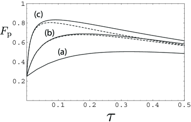
We can quantify the gate performance by calculating the process fidelity of the gate with the ideal csign gate. A general quantum operation on is isomorphic to density matrices in Jamiołkowski (1972) via , where is a maximally entangled state on the two spaces of dimension . The process fidelity is then the fidelity between these process density matrices . The process fidelity is linearly related to the average gate fidelity , via where is the dimension of the system, so that captures the average performance of the gate Horodecki et al. (1999), e.g. it has been shown that bounds the average probability of error in a function computation Gilchrist et al. (2005a). The process fidelity (which is identical whether we use single- or dual-rail encoding) is plotted in Fig. 2 for a range of . The most striking feature of the figure is that there is an optimum interaction time for a given , and also that the maximum fidelity is not unity. The existence of this optimum is intuitive — too short an interaction time and there has been insufficient two photon absorption for the gate to function, and too long an interaction time and the effect of the single photon loss starts to dominate. We will assume for the remainder of the paper that for the task at hand.
This behaviour of the fidelity with photon loss is also seen in high efficiency interaction free measurement Kwiat et al. (1999) which also makes use of the quantum Zeno effect. In a nutshell, the high efficiency limit requires long interaction times which enhances the effect of any loss.
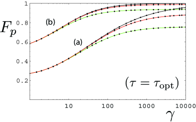
In Fig. 3 (a) we examine the scaling of the process fidelity with . Note that though the final limit is unit fidelity, it becomes increasingly difficult to attain higher process fidelities, with the cost in becoming super-exponential for high fidelities.
The chief failure mode of the gate at long interaction times is photon loss. If we could protect the qubits specifically against this type of loss we can expect a significant boost to the fidelity of the gate. We can use a protocol from LOQC for this task which has two levels Ralph et al. (2005). At the first level the qubits are encoded in a parity code over physical qubits. A parity is a superposition of all the even parity components, and a parity is all the odd parity components:
| (3) | ||||
| (4) |
The key property of this code is that a measurement of one of the physical qubits in the computational basis results in a heralded bit-flip on the encoded qubit but does not measure the encoded qubit. This code allows recovery from teleportation failures in KLM style protocols, giving multiple attempt at nondeterministic teleportation. Such codes have already been demonstrated experimentally O’Brien et al. (2005).
If we know from which physical dual-rail qubit the photon has been lost, the parity code translates photon loss into an unheralded bit-flip on that qubit. Photon loss acts as if the environment had measured the qubit but we do not have access to the result so the state is left in a mixture of obtaining both measurement outcomes. In order to recover from this unheralded bit-flip a simple repetition code suffices and the full encoding becomes:
| (5) |
where parity qubits are tensored together. The code can be optimised by carefully choosing the values of and . In this paper, we will assume that the only source of loss is the nonlinear interaction so that a value of will be sufficient, so that the basic parity qubits will be Bell states: and .
To perform a csign on the encoded qubits we attempt the gate on two photons, one from each qubit, then immediately measure the qubits in the basis and determine if a photon was lost or not. If we successfully obtain a result from the measurements (i.e. no photon was lost) we then measure the remaining parity qubit in the computational basis, resulting in a csign being implemented on the remainder of the code (local phase-flips may need to be applied depending on the measurement results). On the other hand, if one or both detectors fail to register an event then we remove the affected part of the redundancy code by measuring the remaining parity qubit in the basis (again phase-flip corrections may need to be applied).
Applying the gate to encoded qubits and considering the conditional case where no photons have been lost (in the case of loss we recover the qubits and try again) we obtain the fidelity in Fig. 3 (b). This fidelity also has an optimum value with after which it reduces with larger . The reason is that loss from the gate is unbalanced: the component suffers no loss while a component with suffers loss. In the long limit states get skewed towards reducing the average fidelity. We can ‘balance’ the gate by also including single photon loss in the arms of Fig. 1, in this case the gate has an optimum fidelity of 1 (in the long limit).
Increasing the fidelity comes at a price — each attempt of the gate consumes four qubits from the code. In the cases where we detect photon loss the protocol resets the qubits to their original state and we need to attempt the gate again. The lower the probability of success the more qubits we consume on average per successful gate operation. We need to balance the trade-off between fidelity of the gate operation and the amount of resources consumed.
In the unbalanced case, the success probability is also state-dependent. Since the polarisation encoded gate acts on only the component and we are modelling loss only in the nonlinear device, the maximum loss is suffered by the component, while the component suffers no loss. This means that detecting a photon loss event will do a partial measurement of the qubits in the computational basis, but this does not pose a problem since the parity code is specifically designed for this scenario.
We can quantify the success probability in both the balanced and unbalanced cases by the average probability of success
| (6) |
where the integral is over the Haar measure for all two-qubit pure states , and are the successful measurement results after the gate. Because of the linearity of the trace and the operation this reduces to , where is the identity in the two-qubit subspace where the photons have not been lost.
Say we are given two logical qubits encoded over some number of photons and the goal is to produce a cnot or csign gate with a process fidelity , and a probability of catastrophic failure (we lose all the photons and hence the logical qubits). We can compare against a competing LOQC protocol such as the gate described in Gilchrist et al. (2005b) which acts on parity encoded qubits. Given optimal encoding in both protocols, at what value of does the quantum Zeno gate begin to use fewer resources than the LOQC gate?
Assuming that the target fidelity can be met automatically, the LOQC gate’s performance is governed entirely by and this determines the minimum size of the parity code needed. The probability of operation per attempt is and so . Since each attempt consumes 3 photons (one each from control, target and resource) and all the control qubits photons have to be measured out at the end, the average number of photons consumed per successful gate operation will be . For the gate presented in this paper, achieving the target fidelity is determined by the ratio of absorptions , which in turn determines the probability of success , and hence the average number of photons consumed per successful gate operation is (we consume four photons per attempt). The probability of catastrophic failure is determined by the size of the code and is independent of the consumption since we do not have to re-encode for a successful gate operation as in Gilchrist et al. (2005b).
If the target fidelity is then a of around 4000 is needed for the unbalanced gate, but this gate consumes 7 times less resources than the LOQC scheme for and 15 times less resources for . By using the balanced version, can be traded off against probability (and hence resource consumption) so for example, at and the Zeno gate still consumes around five times less photons.
We have investigated the performance of the quantum Zeno gate in the presence of single photon absorption. Under this noise the raw gate fidelity is severely hampered, even when the nonlinear two photon absorption rate is some four orders of magnitude larger than the single photon loss rate. However, if such a gate was used within a context of error correction, we have found that higher gate performance can be achieved at the cost of consuming a resource in the form of the logical qubit encoding. Even more promising, there are parameter regions where a high fidelity is achieved with high efficiency, and the resource consumption is less than for corresponding LOQC protocols. Also by restricting the gate operation to certain tasks Leung and Ralph (2006) it is likely that further savings could be achieved. It should be noted that the technique presented here is not specific to the quantum Zeno gate and could be used to mitigate loss in other nonlinear gates. Being able to tolerate some amount of photon loss in its operation makes the practical design of such gates far less stringent and consequently more attractive.
We would like to thank Andrew White, Andrew Doherty and Tim Ralph for helpful discussions. CRM is supported in part by NSERC, ARO, CIAR, MITACS and the Lazaridis Fellowship, and AG is supported by the Australian Research Council and the DTO-funded U.S. Army Research Office Contract No. W911NF-05-0397.
References
- (1) alexei@physics.uq.edu.au
- Franson et al. (2004) J. D. Franson, B. C. Jacobs, and T. B. Pittman, Phys. Rev. A 70, 062302 (2004).
- Franson and Hendrickson (2006) J. D. Franson and S. M. Hendrickson, Phys. Rev. A 74, 053817 (2006).
- Kok et al. (2005) P. Kok, et al., quant-ph/0512071 (2005).
- Misra and Sudarshan (1977) B. Misra and E. C. G. Sudarshan, J. Math. Phys. 18, 756 (1977).
- Jamiołkowski (1972) A. Jamiołkowski, Rep. Math. Phys. 3, 275 (1972).
- Horodecki et al. (1999) M. Horodecki, P. Horodecki, and R. Horodecki, Phys. Rev. A 60, 1888 (1999).
- Gilchrist et al. (2005a) A. Gilchrist, N. K. Langford, and M. A. Nielsen, Phys. Rev. A 71, 062310 (2005a).
- Kwiat et al. (1999) P. G. Kwiat, et al., Phys. Rev. Lett. 83, 4725 (1999).
- (10) As an alternative we can model our csign as an array of partially transmitting beam splitters with one- and two-photon loss in between each. We can solve for the output of the ’th beam splitter/loss combination by solving a set of recurrence equations along with Eq. (2) with .
- Ralph et al. (2005) T. C. Ralph, A. J. F. Hayes, and A. Gilchrist, Phys. Rev. Lett. 95, 100501 (2005).
- O’Brien et al. (2005) J. L. O’Brien, et al., Phys. Rev. A 71, 060303 (2005).
- Gilchrist et al. (2005b) A. Gilchrist, A. Hayes, and T. Ralph, quant-ph/0505125 (2005b).
- Leung and Ralph (2006) P. M. Leung and T. C. Ralph, quant-ph/0609224 (2006).