Ultrahigh finesse Fabry-Perot superconducting resonator
Abstract
We have built a microwave Fabry-Perot resonator made of diamond-machined copper mirrors coated with superconducting niobium. Its damping time ( ms at 51 GHz and 0.8 K) corresponds to a finesse of , the highest ever reached for a Fabry-Perot in any frequency range. This result opens many perspectives for quantum information processing, decoherence and non-locality studies.
pacs:
42.50.Pq, 03.67.-a, 84.40.-x, 85.25.-jSince Bohr-Einstein’s photon box thought experiment, storing a photon for a long time has been a dream of physicists. Cavity quantum electrodynamics (CQED) in the microwave domain comes closest to this goal. Photons are trapped in a superconducting cavity and probed by atoms crossing the field one at a time. Experiments with circular Rydberg atoms and Fabry-Perot resonators have led to fundamental tests of quantum theory and various demonstrations of quantum information procedures rmp . The open geometry of the cavity is essential to allow a perturbation-free propagation of long-lived atomic coherences through the mode. With this cavity structure, however, the field energy damping time is very sensitive to geometrical mirror defects, limiting to ms in previous experiments. We report here the realization of a Fabry-Perot resonator at GHz, with ms. The cavity quality factor is and its finesse , the highest ever achieved in any frequency domain for this geometry. This important step opens the way to many CQED experiments. Quantum non-demolition detection of a single photon Gleyzes06 and generation of mesoscopic non-local quantum superpositions Milman2005 are now accessible. Long term storage of single photon fields opens bright perspectives for quantum information processing. These high- cavities are also promising for the stabilization of microwave oscillators or for the search of exotic particles rmpaxion .
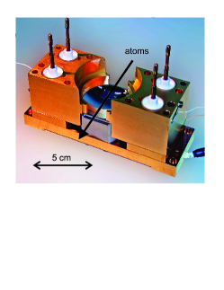
A picture of the cavity with the top mirror removed is shown in Fig. 1. The mirrors have a diameter mm. The distance between their apexes is mm. Their surface is toroidal (radii of curvature 39.4 and 40.6 mm in two orthogonal planes). The two TEM900 modes near GHz with orthogonal linear polarizations are separated by MHz. This large frequency splitting is essential to ensure that atoms are efficiently coupled to a single mode only. The mirrors are electrically insulated. A static electric field parallel to the cavity axis is applied between them to preserve the circular states and to tune the atomic transition via the Stark effect rmp . The 1 cm spacing between mirror edges is partly closed by two guard rings improving the static field homogeneity in . The atoms of a thermal beam enter and exit the cavity through two large ports ( cm cm) so that they never come close to metallic surfaces, preserving them from patch effect stray fields. This ensures a good transmission of atomic coherences through the cavity Gleyzes06 . Four piezoelectric actuators are employed to translate one of the mirrors and to tune the cavity (within MHz) with a few Hz accuracy.
We realized two mirror sets, and . The copper substrates are first machined to a gross spherical shape. They are then submitted to two temperature cycles to release stresses. They are first heated in a vacuum chamber to C and cooled down to liquid temperature. The final diamond machining is then performed (Kugler company). The local surface roughness is nm r.m.s. and the surface has a peak-to-valley deviation of nm from the ideal shape. To avoid deformation of the mirrors in the final assembly, their thickness is mm. Their back surface and that of the matching holders are polished to m.
The mirror surface is covered with a m-thick layer of Nb. We use a coating facility at CEA, Saclay, designed for r.f. cavities used in particle accelerators CEA_accelerators . The Nb layer is deposited by d.c. cathode sputtering in a magnetron discharge CEA_sputtering . We first clean the substrate with ultra-pure filtered alcohol (ultrasonic bath) and dry it with filtered Ar. The sputtering chamber is evacuated to mbar and then filled with mbar of Ar. We set the mirror potential to V for s, creating an Ar plasma which blows away residual dust particles. The chamber is evacuated again and we start the sputtering process. A kW magnetron creates a dense Ar plasma in the vicinity of a cylindrical Nb cathode (Ar pressure during sputtering: 10-3 mbar). Initially, the Nb cathode is far away from the mirror. When its impure surface layer is removed, we move it in front of the mirror. The evaporated atoms are deposited at a rate of m/min on the mirror surface, which heats up to C. Before being mounted in the Rydberg atom set-up, the mirrors are finally rinsed in an alcohol ultrasonic bath and dried with Ar.
In order to characterize the cavity modes, microwave is coupled in via weak diffraction loss channels. We thus avoid coupling irises in the mirror centers, which are detrimental to the surface quality rmp . This coupling is large enough to inject a mesoscopic field in , but not to detect directly the decay of the leaking field. We monitor instead the cavity ring-down with an atomic probe. At the beginning of a measurement sequence, we inject a microwave pulse by a waveguide ending in the guard ring around . Most of the microwave power is not coupled into the mode and decays in the apparatus in less than 1 s. After a time interval , we send the Rydberg atom probe in . It is produced by a two-step laser excitation of 85Rb atoms involving a diode laser at nm ( ) and a second diode laser at nm ( ). The cavity field induces transitions from to other Rydberg levels. The absorption is made broadband by the Stark effect in a 13.4 V/cm electric field applied in . Broadband detection is essential for the first cavity tests, since the reproducibility of the mirror mounting results in an uncertainty in the mode frequencies of MHz. The cavity-field-induced atomic transitions are monitored by a state-selective field-ionization detector.
By sweeping the microwave source and recording the atomic absorption, we determine the cavity resonances. For and we find two modes (lower frequency, and higher frequency, , ) close to 51.1 GHz, separated by the expected 1.2 MHz splitting. We have mapped the transverse profile of these modes. Using pulsed velocity-selected atomic samples, we know the atomic position at any time. Switching the Stark field in on and off, we set the atoms in resonance during a short time window, at a well defined position in . The measured transition probability reveals the intensity profile of the mode along the atomic beam axis. We obtain, as expected, a Gaussian with a mm waist.
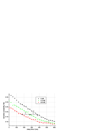
To measure the quality factors, we record the transition probability as a function of the delay . Typical data, obtained with at K is shown in Fig. 2 for three initial field energies, , and ( is the base of natural logarithms), corresponding to microwave source attenuations of 8.6, 4.3 and 0 dB respectively. Due to the exponential decrease of versus time, , an arbitrary energy is reached at times , and for these three attenuations. Since depends only upon , the corresponding curves are time-shifted by with respect to each other. We obtain ms. For , is found to be ms. For and we get, at K, ms and ms respectively. These four modes have all an extremely long energy storage time. The longest one corresponds to a light travel distance of 39 000 km folded in the 2.7 cm space between the mirrors. The corresponding quality factor is and the finesse is .
We have measured the mode spectrum at 0.8 K. The FWHM linewidth is Hz, close to the 1.22 Hz value deduced from . The difference is due to residual low frequency mechanical vibrations (a 1 Hz shift corresponds to a 500 fm translation of one mirror). The cavity drift is less than 3 Hz per hour. The stored field coherence is thus well preserved, an important feature for quantum information storage.
We have studied as a function of the mirror temperature for (Fig. 3). For K, increases exponentially versus , while it saturates for K. The quality factor can be expressed as the ratio of two resistances characterizing the geometry ( here) and the losses () Halbritter1971 . The effective resistance, has three contributions. The resistance is given by BCS theory, the residual resistance at K is due to defects and measures the diffraction losses. The BCS resistance is , where is the superconducting gap and is intrinsic to Nb. For K, dominates , while it is negligible for K. The line in Fig. 3 is a fit with , from which we infer K. This value, confirmed by measurements on and , differs slightly from the value 17.056 K found at 22 GHz with bulk Nb in Ref. Meschede1985 .
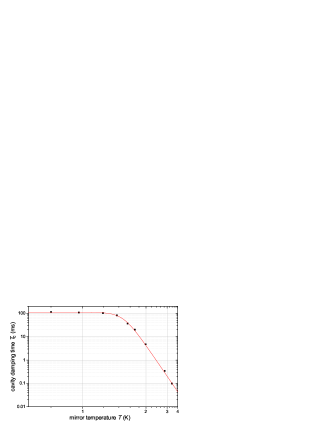
The saturation of below K yields n for and n for . The order of magnitude of the diffraction losses can be estimated. The mirror diameter limits to ( is the mode waist at the mirror surface). The surface roughness is characterized by the r.m.s. deviation, , with respect to the ideal shape. The corresponding quality factor, calculated by evaluating the “total integrated scattering” (TIS) Winkler1994 , is . From the measured nm, we obtain . Combining these losses yields . This is close to the best measured value (), indicating that diffraction losses are the dominant contribution at low .
It is also instructive to compare the factor of our open resonators with that of closed cylindrical cavities at GHz used in Rydberg atom micromaser studies Meschede1985 ; Rempe1990 . In these experiments, at K was measured Walther2001 . The residual resistance was n ( – there are no diffraction losses in this geometry), a value comparable to ours. The difference could be due to diffraction losses in our open geometry, to the frequency dependence of or to variations in the Nb purity. It is remarkable that our open cavity reaches the same as the best closed one in the same frequency domain. At much lower frequencies, around 1 GHz, factors up to have been obtained Cavities1GHz . This frequency domain is however much less convenient for cavity QED experiments.
We have reported the realization of a ultra-high- photon box. This cavity, with its open geometry, is ideally suited for the propagation of atomic coherence through the field mode, atomic interferometry, decoherence studies and quantum information processing experiments. Experiments with two such cavities are of particular interest. A single atom could be used to entangle two mesoscopic fields separated by a macroscopic distance, resulting in the preparation of a non-local quantum state Milman2005 .
Laboratoire Kastler Brossel is a laboratory of Université Pierre et Marie Curie and ENS, associated to CNRS (UMR 8552). We acknowledge support by the Japan Science and Technology Agency (JST), by the EU under the IP projects “QGATES” and “SCALA”, and by a Marie-Curie fellowship of the European Community (S.K.).
References
- (1)
- (2) J. M. Raimond, M. Brune and S. Haroche, Rev. Mod. Phys. 73, 565 (2001).
- (3) S. Gleyzes, S. Kuhr, C. Guerlin, J. Bernu, S. Deléglise, U. Busk Hoff, M. Brune, J. M. Raimond and S. Haroche, Nature (London) in print, quant-ph/0612031.
- (4) P. Milman, A. Auffeves, F. Yamaguchi, M. Brune, J. M. Raimond and S. Haroche, Eur. Phys. J. D 32, 233 (2005).
- (5) R. Bradley , J. Clarke, D. Kinion, L. J. Rosenberg, K. Van Bibber, S. Matsuki, M. Mück and P. Sikivie, Rev. Mod. Phys. 75, 777 (2003).
- (6) P. Bosland, A. Aspart, E. Jacques and M. Ribeaudeau, IEEE Trans. Appl. Supercond. 9, 896 (1999).
- (7) G. Orlandi , C. Benvenuti, S. Calatroni, M. Hauer and F. Scalambrin, Proceedings of the 6th Workshop on RF Superconductivity 2, 676 (1993).
- (8) J. Halbritter, J. Appl. Phys. 42, 82 (1971).
- (9) W. Winkler, R. Schilling, K. Danzmann, J. Mizuno, A. Rüdiger and K. A. Strain, Appl. Opt. 33, 7547 (1994).
- (10) D. Meschede, H. Walther and G. Müller, Phys. Rev. Lett. 54, 551 (1985).
- (11) G. Rempe, F. Schmidt-Kaler and H. Walther, Phys. Rev. Lett. 64, 2783 (1990).
- (12) S. Brattke, B. T. H. Varcoe and H. Walther, Phys. Rev. Lett. 86, 3534 (2001).
- (13) V. Arbert-Engels, C. Benvenuti, S. Calatroni, P. Darriulat, M. A. Peck, A. M. Valente and C. A. Van’t Hof, Nucl. Instrum. Methods A 463, 1 (2001).