Tunable control of the bandwidth and frequency correlations of entangled photons
Abstract
We demonstrate experimentally a new technique to control the bandwidth and the type of frequency correlations (correlation, anticorrelation, and even uncorrelation) of entangled photons generated by spontaneous parametric downconversion. The method is based on the control of the group velocities of the interacting waves. This technique can be applied in any nonlinear medium and frequency band of interest. It is also demonstrated that this technique helps enhance the quality of polarization entanglement even when femtosecond pulses are used as a pump.
pacs:
03.67.Mn, 42.50.Dv, 42.65.LmOne of the goals of quantum optics is to design and implement new sources of quantum light which could enable tunable control of the relevant photonic properties, as required by the specific quantum information applications under consideration.
To date most quantum information applications use the polarization of photons, or polarization entanglement between paired photons, as the quantum resource. In this Letter we present a new technique to appropriately engineer the frequency properties of quantum light, namely, the bandwidth and the type of frequency correlations between paired photons.
The spectrum of photons can be considered as a quantum resource by itself. The frequency content of light, and frequency entanglement, occurs in an infinite dimensional Hilbert space. This offers the possibility to implement quantum algorithms that either inherently live in a higher dimensional Hilbert space (qudits) or exhibit enhanced efficiency in increasingly higher dimensions.
On the other hand, the frequency properties of entangled two-photon states cannot be neglected even when entanglement takes place in the polarization or spatial degrees of freedom. Since the corresponding entangled states make use of only a portion of the total two-photon quantum state, it is required to suppress any frequency ”which-path” information that otherwise degrades the degree of entanglement.
The optimum bandwidth as well as the most appropriate type of frequency correlations between paired photons depend on the specific quantum information application under consideration. Atom-photon interfaces address specific atomic transitions that require ultra-narrow-band quantum light ( MHz), while the generation of ultrahigh fluxes of entangled photons (W) while maintaining their nonclassical properties requires light with largely enhanced bandwidth ( tens of nm) loudon1 ; dayan1 . Some protocols for quantum enhanced clock synchronization and position measurement rely on the use of frequency correlated photons lloyd1 . Heralded single photons with a high degree of quantum purity can be obtained by generation of uncorrelated paired photons. The tolerance against the effects of mode mismatch in linear optical circuits, the dominant cause of photon distinguishability, can be enhanced by using photons with appropriately tailored wave-packet shape rohde1 .
The most widely used method for the generation of pairs of entangled photons is spontaneous parametric downconversion (SPDC) where two lower-frequency photons are generated when a strong pump field interacts with a nonlinear crystal. SPDC with continuous-wave pumping produces frequency anticorrelated photons. Other specific frequency correlations, such as correlated or uncorrelated photons, can occur in special crystals with suitable pump light conditions, specific values of the nonlinear crystal length and dispersive properties of the nonlinear crystals grice1 ; kocuzu1 .
One strategy for engineering the bandwidth is based on the proper preparation of the downconverting crystal. Frequency-entangled pairs of photons with a largely enhanced bandwidth can be generated in chirped quasi-phase-matched nonlinear crystals carrasco3 , while paired photons with a largely reduced spectral width can be generated in cavity SPDC ou1 . Properly designed SPDC configurations with nonlinear crystal superlattices allow tailoring the frequency correlations of paired photons uren1 .
In general, noncollinear SPDC geometries enable to control the bandwidth of downconverted photons as well as the waveform carrasco2 . SPDC configurations where the downconverted photons counter propagate allow to reduce the spectral width of light booth1 ; rossi1 . Noncollinear SPDC allows the generation of frequency-correlated and uncorrelated photons by controlling the pump beam width and the angle of emission of the downconverted photons walton1 ; uren2 .
In this Letter we experimentally demonstrate a new technique to tailor the bandwidth and frequency correlations of entangled photons torres1 that makes possible to generate frequency-correlated, anticorrelated, and even uncorrelated entangled photon pairs. The method is based on the proper tailoring of the group velocities of all interacting waves through the use of beams with angular dispersion, i.e., pulses with pulse-front tilt. The method can be implemented in materials and frequency bands where conventional solutions do not hold.
Let us consider a collinear SPDC configuration with type-II (oee) phase matching. The input pump beam with central angular frequency passes through a medium with angular dispersion, such as a diffraction grating oriented along the transversal -direction. The beam is diffracted by the grating so that each frequency component is dispersed in a different direction. The transformation of the pump beam due to the grating can be written as martinez1 , where is the angular frequency deviation, is the transverse wave-vector, , is the angle of incidence at the grating, is the output diffraction angle, and is the speed of light.
The resulting beam acquires a pulse-front tilt such that its peak intensity is located at a different time for each value of . The tilt angle is , where is the angular dispersion with being the groove spacing of the grating, the diffraction order and . At the output face of the nonlinear crystal (), a second grating is used to re-collimate the beam by compensating for the angular dispersion introduced by the first grating.
The quantum state of the downconverted photons at the output face of the nonlinear crystal writes , where torres1
| (1) |
and , , , , and are the corresponding interference filters in front of the detectors.
Eq. (Tunable control of the bandwidth and frequency correlations of entangled photons) describes an entangled state in both, the signal and idler transverse wavenumber and signal and idler frequency . However, in a specific detection scheme, it has to be projected into the required spatial modes. Here, the detection scheme projects the signal and idler photons into two spatial modes with large areas, i.e. , so that the quantity of interest is .
The effective inverse group velocity (, ) of all interacting waves is torres2 , and the effective inverse group velocity dispersion is , where is the Poynting vector walk-off, is the longitudinal wavenumber, and and are the corresponding inverse group velocity and group velocity dispersion parameters, respectively.
The joint spectral amplitude is determined by the spectral shape of the pump beam and by the corresponding effective phase-matching conditions inside the nonlinear crystal. These depend on the relationship between all the group velocities grice1 . For equal effective group velocities (), one obtains photons highly anticorrelated in frequency (). For , the pair of photons is highly correlated in frequency ().
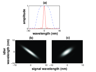
Let us first consider a continuous-wave (CW) pump beam with pulse-front tilt. Fig. 1(a) shows how the bandwidth of the joint spectral intensity of the downconverted photons can be tailored by modifying the tilt angle. For no tilt (), the spectral intensity writes which is typical of type-II SPDC rubin1 .
The condition is achieved for a tilt angle torres1
| (2) |
so that one obtains , which is characteristic of a typical type-I SPDC source, although the process considered is of type-II. We can see that applying a tilt, the spectrum can vary greatly.
Tilted pulses can also be used to tailor the type of frequency correlations of photons when broadband pump pulses are used. Let us define two spectral intensities in the directions , and , respectively. Frequency anticorrelated (correlated) photons correspond to the case where the bandwidth of is much narrower (wider) than the bandwidth of .
For the tilt angle given by Eq. (2), the spectral intensities and write
| (3) |
where . The corresponding joint spectral intensity plotted in Fig. 1(b) shows high frequency anticorrelation. The phase-matching conditions induced by the angular dispersion widen the joint spectral intensity in the direction and they make it narrower in the direction.
The tilt required for the generation of highly frequency-correlated photons, as shown in Fig. 1(c), writes
| (4) |
and the corresponding spectral intensities are
| (5) |
The bandwidth in the direction is mostly determined by the bandwidth of the pump beam, while in the direction we obtain the typical type-II dependence on the frequency.
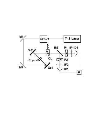
We set up an experiment (see Fig. 2) to demonstrate the feasibility of the technique described above. The second harmonic beam of a femtosecond Ti:Sapphire laser tuned at nm is directed at a diffraction grating () that introduces the appropriate amount of pulse-front tilt () in the plane determined by the pump beam direction of propagation and the optic axis of the nonlinear crystal. The measured bandwidth of the pump beam was nm (FWHM). The pulses diffracted off the grating enter a 2-mm thick BBO crystal where degenerate collinear type-II SPDC occurs. After the downconversion process, the angular dispersion of the downconverted photons is removed by an inverse grating ().
To evaluate the different types of frequency correlations and the bandwidth, a Hong-Ou-Mandel (HOM) interferometer is used hom1 . A variable polarization-dependent delay line made of birefringent quartz is inserted between the nonlinear crystal and the beam splitter, which allows us to add a variable time delay () between the generated paired photons. After the beam splitter, polarizers () are used to control the polarization of the photons. -nm (FWHM) interference filters are located in front of single-photon counting modules, where the coincident arrival of two photons in a time window of ns is measured.
The coincidence rate , where are the angles of the two polarizers, is given by
| (6) |
where .
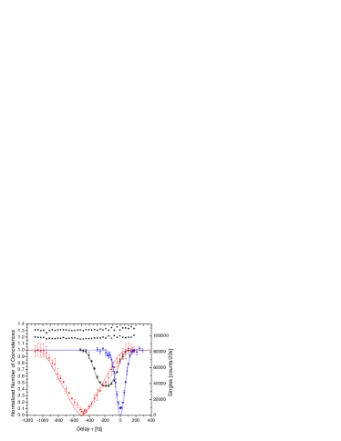
Fig. 3 shows our main experimental results. The normalized number of coincidences (for the sake of comparison) is plotted versus the time delay introduced by the delay line. When no tilt is applied to the pump pulse, the visibility of the HOM dip drops to . The degradation of frequency anticorrelation due to the broadband pump beam introduces distinguishing information between the ordinary and extraordinary downconverted photons. The center of the dip is located at rubin1 .
The tilt angle for anticorrelated photons is and we expect . This amount of angular dispersion is introduced by a grating of 1200 lines/mm and diffraction order . Grating then has 600 lines/mm and . For anticorrelated photons we obtain . The measured visibility of the HOM dip is now . Notice that we generate highly anticorrelated photons even when we are using a broadband pump beam.
The generation of highly correlated photons requires a tilt angle . We expect . A grating with 2400 lines/mm and , and with 1200 lines/mm and are used. The spectral intensity writes . The visibility of the HOM dip goes up to . The shape of the dip is triangular, as corresponds to a typical type-II-like SPDC process rubin1 . The values of measured agree well with the theoretical predictions. In general, the degree of frequency correlation or anticorrelation might be modified by using crystals of different length or filters with different bandwidth.
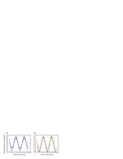
The use of frequency-correlated (anticorrelated) photons allows the erasing of the distinguishing information coming from the spectra of the photons when considering polarization entanglement. Under our experimental conditions, the two-photon quantum state in polarization space writes , where . The purity of the state is and the visibility of is .
Fig. 4(a) shows for frequency anticorrelated photons when the angle is changed. The corresponding case with no tilt is also shown for comparison. The visibility increases from (no tilt) to . Fig. 4(b) shows the case for correlated photons with and . The visibility goes up to in both cases. Thus the purity of the state is greater than 0.95.
In conclusion, we have shown experimentally that the use of pulses with pulse-front tilt allows tailoring the bandwidth and frequency correlations of entangled photons. This technique can be used in any nonlinear crystal and frequency band of interest. Pulses with pulse-front tilt are an important and enabling tool in nonlinear optics, such as in broadband frequency conversion martinez2 ; dubietis1 and soliton phenomena in second order nonlinear media paolo1 ; liu1 . In this Letter, we add the use of tilted pulses to the toolkit of available techniques in quantum optics for the full control of the properties of quantum light.
Pulse-front techniques can also be used in other configurations. In noncollinear SPDC the group velocity can be tailored too, now with the noncollinear emission angle playing the role of the Poynting-vector walk-off angle. Therefore, pulse-front techniques can take advantage of the larger nonlinear coefficient of some materials in combination with quasi-phase-matching techniques.
The recently demonstrated generation of paired photons in electromagnetically induced transparency schemes balic1 can also benefit from the use of tilted pulses to enhance the control of the frequency correlations of the paired photons, as well as to increase the tuning range of the coherence time of the generated photons.
This work was supported by projects FIS2004-03556 and Consolider-Ingenio 2010 QOIT from Spain, and by the European Commission under the Integrated Project Qubit Applications (Contract No. 015848). MH and JPT acknowledges support from the Gov. of Catalonia. MM acknowledges support from the project Center of Modern optics (LCO6007) of the Czech M. of Education.
References
- (1) R. Loudon, The quantum theory of Light, Oxford Univ. Press (2000).
- (2) A. Peer et al., Phys. Rev. Lett. 94, 073601 (2005).
- (3) V. Giovannetti et al., Nature 306, 1330 (2004)
- (4) P. P. Rohde et al., Phys. Rev. A 72, 052332 (2005).
- (5) W. Grice et al., Phys. Rev. A 64, 063815 (2001).
- (6) O. Kocuzu, et al., Phys. Rev. Lett. 94, 083601 (2005).
- (7) S. Carrasco et al., Opt. Lett. 29, 2429 (2004).
- (8) Z. Y. Ou and Y. J. Lu, Phys. Rev. Lett. 83, 2556 (1999).
- (9) A. B. U’Ren et al. Phys. Rev. Lett. 97, 223602 (2006).
- (10) S. Carrasco et al., Phys. Rev. A 70, 043817 (2004); Phys. Rev. A 73, 063802 (2006).
- (11) M. C. Booth et al., Phys. Rev. A 66, 023815 (2002).
- (12) A. De Rossi and V. Berger, Phys. Rev. Lett. 88, 043901 (2002).
- (13) Z. D. Walton et al., Phys. Rev. A 67, 053810 (2003).
- (14) A. B. U’Ren et al., Quantum Inf. Comput. 3, 480 (2003).
- (15) J. P. Torres et al., Opt. Lett. 30, 314 (2005); Phys. Rev. A 71, 0223210 (2005).
- (16) O. E. Martínez, J. Opt. Soc. Am. B 3, 929 (1986).
- (17) M. H. Rubin et al., Phys. Rev. A 50, 5122 (1994).
- (18) J. P. Torres et al., Opt. Lett. 25, 1735 (2000).
- (19) C. K. Hong et al., Phys. Rev. Lett. 59, 2044 (1987).
- (20) O. E. Martínez, IEEE J. Quantum Electron. 25, 2464 (1989).
- (21) A. Dubietis et al., Opt. Lett. 22, 1071 (1997).
- (22) P. Di Trapani et al., Phys. Rev. Lett. 81, 570 (1998).
- (23) X. Liu et al., Phys. Rev. Lett. 82, 4631 (1999).
- (24) V. Balic et al., Phys. Rev. Lett. 94, 183601 (2005).