Present address: ]Los Alamos National Laboratory, Los Alamos, NM 87545, USA. Present address: ]University of Ulm, 89069 Ulm, Germany.
Errors in trapped-ion quantum gates due to spontaneous photon scattering
Abstract
We analyze the error in trapped-ion, hyperfine qubit, quantum gates due to spontaneous scattering of photons from the gate laser beams. We investigate single-qubit rotations that are based on stimulated Raman transitions and two-qubit entangling phase-gates that are based on spin-dependent optical dipole forces. This error is compared between different ion species currently being investigated as possible quantum information carriers. For both gate types we show that with attainable laser powers the scattering error can be reduced to below current estimates of the fault-tolerance error threshold.
pacs:
03.67.Lx, 03.65.Yz, 03.67.Mn, 32.80.-tI INTRODUCTION
Quantum bits, or qubits, that are encoded into internal states of trapped ions are an interesting system for Quantum Information Processing (QIP) studies CiracZoller ; bible . Internal states of trapped ions can be well isolated from the environment, and very long coherence times are possible bible ; Wunderlich ; HighField ; Oxford_LongCoherence . The internal states of several ion-qubits can be deterministically entangled, and quantum gates can be carried out between two ion-qubits entanglement ; Innsbruck_entanglement ; SackettGate ; Didi_gate ; Innsbruck_gate ; Michigan_gate ; Oxford_gate .
Among different choices of internal states, qubits that are encoded into pairs of ground state hyperfine or Zeeman states benefit from negligible spontaneous decay rates bible . The small energy separation between the two states of such qubits (typically in the radio-frequency or microwave domain) allows for phase coherence between a local oscillator and a qubit superposition state over relatively long times bible ; HighField ; Bollinger_longCoherence ; Fisk .
The quantum gates that are performed on hyperfine ion-qubits typically use laser beams. Since light couples only very weakly to the electron spin, spin manipulations rely instead on the spin-orbit coupling of levels that are typically excited non resonantly through allowed electric dipole transitions. Spin manipulations therefore require a finite amplitude in the excited electronic state, and spontaneous scattering of photons from the laser beams during the gate is inevitable.
Fault-tolerant quantum computation demands that the error in a single gate is below a certain threshold. Current estimates of the fault-tolerance error threshold range between to Steane_FT ; Reichardt_FT ; Knill_FT . These estimates rely on specific noise models and error-correction protocols and should be considered as guidelines only. However, the general view is that for fault tolerance to be practical, the error probability in quantum gates should be at least as small as . It is, therefore, worth exploring the limitations to the fidelity of quantum gates performed on trapped ions with laser light, using this level of error as a guideline PlenioKnight .
In his 1975 paper Mollow , Mollow showed that the effect of a quantum coherent field on an atom is equivalent to that of a classical field plus a quantum vacuum field. The error due to the interaction with light can be categorized into two parts. The first is the error due to noise in classical laser parameters, such as intensity or phase bible ; Milburn98 . The second part originates from the quantum nature of the electromagnetic field and is due to vacuum fluctuations, i.e. the spontaneous scattering of photons Wayne ; SilberfarbDeutsch .
I.1 Ion-qubit levels and transitions
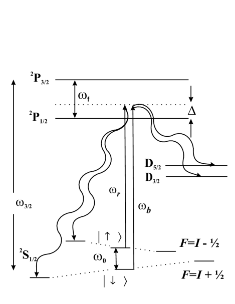
Most ion species considered for QIP studies have a single valence electron, with a electronic ground state, and and electronic excited states. Some of the ions also have D levels with lower energy than those of the excited state P levels. Ions with a non zero nuclear spin also have hyperfine structure in all of these levels. A small magnetic field is typically applied to remove the degeneracy between different Zeeman levels. Here we consider qubits that are encoded into a pair of hyperfine levels of the manifold. Figure 1 illustrates a typical energy level structure.
To allow for a straightforward comparison between different ion species, we investigate qubits that are based on clock transitions, i.e. a transition between the and hyperfine levels in the manifold of ions with a half odd-integer nuclear spin , at a small magnetic field. For this transition, the total Raman and Rayleigh photon scattering rates, as well as the Rabi frequency, are independent of , and the comparison between different ion species depends only on other atomic constants. Superpositions encoded into these states are also more resilient against magnetic field noise Wunderlich ; Oxford_LongCoherence ; Michigan_gate . Even though our quantitative results apply only to this configuration, for other choices of hyperfine or Zeeman qubit states (including those with ) the results will not change significantly.
Gates are assumed to be driven by pairs of Raman beams detuned by from the transition between the and the levels (See Fig. 1). We further assume that the Raman beams are linearly polarized and Raman transitions are driven by both photon pairs and photon pairs. The two beams in a Raman pair are designated as red Raman () and blue Raman () by their respective frequencies. In the following we also assume that is much larger than the hyperfine and Zeeman splitting between levels in the ground and excited states.
The Rabi frequency between the two clock states is London
| (1) |
where , is the peak electric field of the or beam at the position of the ion, respectively, and is the right circular component of the electric dipole operator. The right and left circular polarization components of the and beams are and , respectively. The and excited levels are separated by an angular frequency .
The total spontaneous photon scattering rate from these beams is given by London
| (2) |
Here is the natural linewidth of the and levels gRemark . We now assume linearly polarized Raman beams with London . We further assume . The time for a rotation is
| (3) |
Combining Eq. (1),(2) and (3), the probability to scatter a photon during is given by
| (4) |
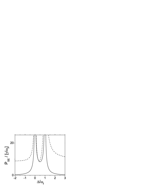
The dashed line in Fig. 2 shows vs. , where the laser detuning is expressed in units of the excited state fine-structure splitting, and the scattering probability is given in units of . The total scattering probability has a global minimum of
| (5) |
when the laser detuning is between the two fine-structure manifolds (). The asymptotic value of for large positive or negative detuning
| (6) |
is only slightly larger than the global minimum.
Previous studies estimated decoherence by assuming that any photon scattering will immediately decohere a hyperfine superposition London . Under this assumption the lowest possible gate error equals and ions with a small ratio benefit from a lower gate error minimum.
Two kinds of off-resonance photon scattering occur in the presence of multiple ground states. Inelastic Raman scattering which transfers population between ground states, and Rayleigh elastic scattering which does not change ground state populations. Since no energy or angular momentum are exchanged between the photon and the ion internal degrees of freedom, no information about the qubit state is carried away by a Rayleigh scattered photon. Rayleigh scattering, therefore, does not necessarily lead to decoherence London ; cline94 ; spont_paper . This was experimentally shown in spont_paper where, when of equal rate from both qubit levels, off-resonance Rayleigh scattering of photons did not affect the coherence of a hyperfine superposition. Decoherence in the presence of light was shown to be dominated by Raman scattering. The guideline used in London is therefore overly pessimistic.
In this paper we re-examine the errors due to spontaneous photon scattering on single-qubit gates (rotations of the equivalent spin vector on the Bloch sphere) and two-qubit (entanglement) gates, where the qubits are based on ground state hyperfine levels and manipulated with stimulated Raman transitions. We compare between different ion species and examine different Raman laser parameters. In section II we analyze the contribution to the gate error due to spontaneous Raman scattering. Following a Raman scattering event the ion-qubit is projected into one of its ground states and spin coherence is lost. This error was also addressed in Gea-Banacloche . In section III we examine the error due to Rayleigh scattering. Rayleigh scattering error results primarily from the photon’s recoil momentum kick. We show that both types of gate errors can be reduced to small values, while keeping the gate speed constant, with the use of higher laser intensity.
II RAMAN SCATTERING ERROR
In a Raman photon scattering event energy and angular momentum are exchanged between the scattered photon and the ion’s internal degrees of freedom. The polarization and frequency of the scattered photon (with respect to those of the laser) become entangled with the ions’ internal state. Therefore, after tracing out the photon degrees of freedom, the ions’ spin coherence is lost. In other words, Raman scattering serves as a measurement of the ion-qubit internal state. Following a spontaneous Raman scattering event the ion-qubit is projected into one of the ground states in the manifold. For ions with low lying D levels, Raman scattering events can also transfer the ion from the qubit levels into one of the D levels.
II.1 Single-qubit gate
For a single qubit gate we choose to look at the fidelity of a rotation around the -axis of the Bloch sphere, represented by the Pauli operator . This gate is assumed to be driven by a co-propagating Raman beam pair, where the frequency difference between the beams equals the frequency separation between the two qubit states . It is straightforward to generalize this case to other rotations.
As a measure of the error in the rotation, we use the fidelity of the final state (characterized by density matrix ) produced by the erroneous gate as defined by
| (7) |
where is the ideal final state. Given an initial state , can be written as
| (8) |
In the presence of off-resonance Raman scattering, the density matrix that describes the state of the qubit after the gate has the form
| (9) |
The erroneous part of the density matrix , is composed of projectors into different levels of lower energy. Here is the probability for a spontaneous Raman scattering event to occur during the gate.
Note that some Raman scattering events keep the ion within the qubit manifold. Using Eq. (7) the contribution of to the fidelity is positive and not strictly zero. For simplicity, we neglect this contribution and put a lower bound on the gate fidelity
| (10) |
In what follows we assume this expression to be an equality. The error in the gate due to spontaneous Raman photon scattering is hence given by the Raman scattering probability
| (11) |
We first examine the error due to Raman scattering back into the manifold . The Raman scattering rate back into the manifold is calculated to be spont_paper
| (12) |
For the same laser parameters as above, the probability to scatter a Raman photon during the gate is
| (13) |
The solid line in Fig. 2 shows vs. . The Raman scattering probability decays quadratically with for . Qualitatively, this is because Raman scattering involves a rotation of the electron spin. Electron spin rotations are achieved through the spin-orbit coupling in the excited state. This coupling has opposite sign contributions from the two fine-structure levels. Therefore as we detune far compared to the fine structure splitting, those two contributions nearly cancel cline94 .
Using Eq. (1) we can write
| (14) |
The ratio can be expressed in terms of atomic constants, and the peak electric field amplitude at the position of the ion gRemark
| (15) |
Here is the frequency of the transition between the and the levels (D2 line), is the vacuum permittivity, and is the speed of light. Assuming Gaussian laser beams, at the center of the beam
| (16) |
Here is the power in each of the Raman beams and is the beam waist at the position of the ion. The probability to scatter a single Raman photon can be written as
| (17) |
| Ion | I | (MHz) | (GHz) | (THz) | (nm) | (nm) | |
|---|---|---|---|---|---|---|---|
| 9Be+ | 3/2 | 19.6 | 1.25 | 0.198 | 313.1 | 313.0 | N.A. |
| 25Mg+ | 5/2 | 41.3 | 1.79 | 2.75 | 280.3 | 279.6 | N.A. |
| 43Ca+ | 7/2 | 22.5 | 3.23 | 6.68 | 396.8 | 393.4 | 17 |
| 67Zn+ | 5/2 | 62.2 | 7.2 | 27.8 | 206.2 | 202.5 | N.A. |
| 87Sr+ | 9/2 | 21.5 | 5.00 | 24.0 | 421.6 | 407.8 | 14 |
| 111Cd+ | 1/2 | 50.5 | 14.53 | 74.4 | 226.5 | 214.4 | N.A. |
| 137Ba+ | 3/2 | 20.1 | 8.04 | 50.7 | 493.4 | 455.4 | 3 |
| 171Yb+ | 1/2 | 19.7 | 12.64 | 99.8 | 369.4 | 328.9 | 290 |
| 199Hg+ | 1/2 | 54.7 | 40.51 | 273.4 | 194.2 | 165.0 | 700 |
This result is essentially the same as Eq. (5) of Gea-Banacloche . We can now rearrange this expression to put an upper bound on the required power for a desired gate speed and error
| (18) |
where .
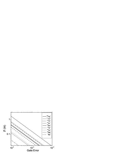
Assume that the ratio of the beam waist to the transition wavelength is constant for different ion species. In this case, the power needed to obtain a given Rabi frequency and to keep the error below a given value would scale linearly with the optical transition frequency. A more realistic assumption might be that the Raman beam waist is not diffraction limited and is determined by other experimental considerations, such as the inter-ion distance in the trap or beam pointing fluctuations. In this case, assuming that is constant, the required power would scale as the optical transition frequency cubed. Either way, ion species with optical transitions of longer wavelength are better suited in the sense that less power is required for the same gate speed and error requirements. In addition, high laser power is typically more readily available at longer wavelengths. Finally, we note that the error is independent of the fine-structure splitting as long as we have sufficient power to drive the transition. The transition wavelengths of different ions are listed in Table 1.

Figure 3 shows the laser power needed per Raman beam for a given error due to spontaneous Raman scattering into the manifold. Here we assume = 0.25 MHz ( sec), and = 20 m. Different lines correspond to the different ion species listed on the figure legend. Table 2 lists the error in a single ion-qubit gate due to Raman scattering back into the manifold for the same parameters as in Fig. 3, and assuming mW in each of the Raman beams. The power needed in each of the gate beams for is also listed in the table. As can be seen, ions with shorter transition wavelength require a larger detuning and accordingly higher laser power to maintain a low gate error. For most ions, a few milliwatts of laser power is enough to reduce the gate error to below .
Equation (13) can be solved to give the required detuning values for a given . The number of such detuning values comes from the number of crossings of a horizontal line, set at the desired error level, with the solid curve in Fig. 2. When is higher than the minimum inside the fine-structure manifold, i.e. (see Fig. 2), then four different detuning values yield the same , two outside and two inside the fine-structure manifold. When is lower than this value, only two detuning values, both of which are outside the fine-structure manifold, yield . Those detuning values that are below the transition () and correspond to are listed in Table 2 for different ions. For most ions is in the few hundred gigahertz range, and its magnitude is much smaller than .
We now consider the error for various ions caused by Raman scattering into low lying D levels, . As transitions between levels in the S and the D manifolds do not necessarily involve electron spin rotations, the error suppression discussed preceding Eq. (13) will not occur. Instead, Raman scattering rate into the D levels will be given by the total scattering rate times a fixed branching ratio . When driven resonantly the and levels decay to the D manifold with different (but often similar) branching ratios. Here we assume that for a detuning large compared to the fine-structure splitting, the branching ratio is essentially independent of the laser detuning and is given by the average of the two resonant branching ratios D1 remark ; D2 remark . Table 1 lists , for various ion species, obtained from f1 ; f2 ; f3 ; f4 ; f5 . The error due to Raman scattering into D levels is given by
| (19) |
Using Eq. (13) we can write the ratio of the errors due to Raman scattering into the different manifolds
| (20) |
For , Raman scattering error is dominated by scattering back into the levels. For ions with the two errors become comparable at a detuning . When the detuning becomes large compared to the fine-structure splitting, scattering into low-lying D levels dominates. For most ions considered here, and (perhaps with the exception of 137Ba+) is the more dominant source of error. The ratios when (i.e. ) are given in Table 2 for different ions.
Due to the asymptotic value of the total scattering rate in the limit (Eq. (6)), has an asymptotic value which gives a lower bound to the Raman scattering error
| (21) |
Table 2 lists for various ions. For all ion species considered this value is below the assumed estimates for the fault tolerance threshold.
| Ion | (mW) | (GHz) | / | ||
|---|---|---|---|---|---|
| 9Be+ | 3.4 | -203 | N.A. | N.A. | |
| 25Mg+ | N.A. | N.A. | |||
| 43Ca+ | |||||
| 67Zn+ | N.A. | N.A. | |||
| 87Sr+ | |||||
| 111Cd+ | N.A. | N.A. | |||
| 137Ba+ | |||||
| 171Yb+ | |||||
| 199Hg+ |
II.2 Two-qubit gate
A universal quantum gate set is complete with the addition of two-qubit entangling gates. During the last few years there have been several proposals and realizations of two ion-qubit gates CiracZoller ; SMgate ; Solano ; Milburn ; SackettGate ; Didi_gate ; Innsbruck_gate ; Michigan_gate ; Oxford_gate . Here we focus on gates that use spin-dependent forces in order to imprint a geometric phase on certain collective spin states SMgate ; Solano ; Milburn ; SackettGate ; Didi_gate ; Michigan_gate ; Oxford_gate . We examine only gates that are implemented with a continuous non resonant pulse rather than those using multiple short pulses pulsed gate . Again, to compare different ion species we examine ion-qubits that are encoded into hyperfine clock states. When the laser detuning is large compared to the hyperfine splitting, the differential light force between clock levels is negligible HighField ; PJLee . However, a phase gate can be applied between spin states in the rotated basis (superpositions of clock states that lie on the equatorial plane of the Bloch sphere) SMgate ; Solano . In this scheme the ions traverse a trajectory in phase space that is conditioned on their mutual spin state (in the rotated basis Michigan_gate ). The phase the ions acquire is proportional to the total area encircled in phase space. This geometric phase gate was demonstrated in SackettGate and was realized on clock states in Michigan_gate .
This form of phase gate is implemented with two different Raman fields that are slightly off-resonance with upper and lower motional sidebands of the spin-flip transition. For simplicity, we assume here that the gate is driven by two independent pairs of Raman beams, i.e. a total of four beams. Most experimental implementations of this phase gate thus far have used a three-beam geometry SackettGate ; Michigan_gate . It is straightforward to generalize the treatment below to the three-beam case.
Typical conditions for the gate are such that the angular frequency difference between the beams is in one Raman pair and in the other. Here is the angular frequency of the normal mode that the gate excites and is the Raman field detuning from that motional sideband. Under these conditions the ions will traverse full circles in phase space for a gate duration of . Typically is chosen to be much smaller than to avoid coupling to the pure spin flip (“carrier”) transition or the motional “spectator” mode, and is usually chosen to be 1 to minimize the gate time.
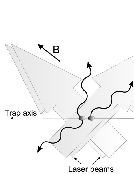
Figure 4 depicts the assumed geometry of the laser beams. The two beams comprising each Raman pair intersect at right angles at the position of the ions, such that the difference in their wave vectors is parallel to the trap axis. With this choice, the Raman fields couple, to a very high degree, only to the motion along the trap axis. The beam polarizations are assumed to be linear, perpendicular to each other and to the magnetic field axis. The beams’ relative frequencies can be arranged such that the final state is insensitive to the optical phase at the ions’ position PJLee . Generalizing this treatment to other Raman beam geometries is straightforward.
As in the single-qubit case, Raman scattering will project one of the ion qubits into one of its states below the P manifold. In the appropriate basis the ideal gate operation is represented by Didi_gate ; Michigan_gate
| (22) |
where typically . The output state is . The density matrix following the erroneous gate will be of the form
| (23) |
where is the probability that one of the ions scattered a Raman photon during the gate No Correlation Remark ; multiple scattering remark . For a gate consisting of circles, the Raman detuning is chosen such that the gate time is given by SMgate
| (24) |
Here is the Lamb-Dicke parameter, where is the wave vector difference between the two beams that drive the gate (for the particular geometry of Fig. 4), and is the laser beam wave vector magnitude. The root mean-square of the spatial spread of the ground state wave function of one ion for the normal mode that the gate excites is
| (25) |
where is the mass of an individual ion. The single ion carrier Rabi frequency is given in Eq. (1).
Using similar considerations to those used in the single ion gate and, as before, neglecting any (positive) contribution of to the fidelity, we can set an upper bound for the power needed for a certain error in the gate due to Raman photon scattering into levels
| (26) |
This required gate power is times larger than that needed for the same error in the single ion-qubit rotation given in Eq. (18). The factor of is due to the longer two ion-qubit gate duration compared to single qubit rotations, and the factor of is due to the presence of two ions and the pair of required Raman fields.
When comparing different ion species we can fix different parameters, depending on experimental constraints or requirements. For example, here we choose as fixed parameters the beam waist (for the reasons given above), the gate time (assuming a certain computation speed is desired), and the mode frequency (which sets the time scale for various gates). With these choices, heavier ions pay the price of smaller and therefore higher power requirements per given gate time and error. A different approach would be to choose fixed, in which case heavier ions will need a lower . For a fixed gate time a lower leads to stronger, off-resonant, coupling of the Raman fields to the carrier or the other motional “spectator” mode, and, therefore, to a larger error due to this coupling SMgateThermal ; heavier ions . The Lamb-Dicke parameters for the different ions for = 5 MHz are listed in Table 3.
With the choice where , , and are fixed, we can write
| (27) |
Or equivalently,
| (28) |
Figure 5 shows the power needed vs. error in a two-qubit gate due to Raman scattering back into the manifold for = 20 m, = 10 s, = 5 MHz and = 1. Table 3 lists for the various ion species and the same laser parameters as Fig. 5, assuming a power of mW is used in each of the four Raman beams. Alternatively, the power and the detuning needed in each of the gate beams for = are also listed in the table. Here, heavier ions need a larger detuning and correspondingly higher laser power to maintain a low gate error. For most ion species, hundreds of milliwatts of laser power per beam and a detuning comparable or even larger than are needed to reduce the gate error to the level.
As in the one-ion gate, Raman scattering into low lying D levels will add to the gate error. This error is given by
| (29) |
Here is the probability that one of the ions scattered a photon during the two-qubit gate, and is the one-qubit gate scattering probability given in Eq. (4). Since both the Raman and the total scattering probabilities increase by the same factor as compared to the one-qubit gate, the ratio of the two errors will remain the same as given by Eq. (20). Table 3 lists for the different ions when = . Notice that for = some ions require . For those ions is no longer negligible compared to .
Scattering into a low lying D level will, again, set a lower bound on the total error. Combining Equations (29) and (6) we find this lower bound to be
| (30) |
Table 3 lists for the different ion species.
| Ion | (mW) | (THz) | ||||
|---|---|---|---|---|---|---|
| 9Be+ | 3.6 | 36 | -1.20 | N.A. | N.A. | 0.194 |
| 25Mg+ | 11.1 | 111 | -7.28 | N.A. | N.A. | 0.130 |
| 43Ca+ | 13.6 | 136 | -10.42 | 1.01 | 1.06 | 0.071 |
| 67Zn+ | 41.1 | 411 | -24.96 | N.A. | N.A. | 0.11 |
| 87Sr+ | 26.5 | 265 | -20.34 | 0.52 | 0.50 | 0.048 |
| 111Cd+ | 64.3 | 643 | -35.44 | N.A. | N.A. | 0.081 |
| 137Ba+ | 37.4 | 374 | -30.67 | 1.65 | 1.46 | 0.034 |
| 171Yb+ | 57.5 | 575 | -32.89 | 0.01 | 0.007 | 0.038 |
| 199Hg+ | 149.7 | 1497 | -49.52 | 0.003 | 0.001 | 0.078 |
III RAYLEIGH SCATTERING ERROR
Since Rayleigh photon scattering is elastic, no energy or angular momentum is transferred between the photons’ and the ions’ internal degrees of freedom. Therefore, these degrees of freedom remain uncorrelated. Rayleigh scattering does not necessarily lead to direct spin decoherence.
In situations where Rayleigh scattering rates from the two ion-qubit states are different, Rayleigh scattering of photons will eventually measure the qubit state and lead to decoherence. In fact, the most common ion-qubit detection method relies on state selective Rayleigh scattering of photons on a cycling transition. In most Raman gates, however, the laser is detuned from resonance by much more than the qubit levels’ energy separation, , and the laser polarization is typically linear to suppress differential Stark shifts. Under these conditions Rayleigh scattering rates from the two qubit levels are almost identical and the error due to the rate difference is negligible. For the clock transition qubit states considered here, Rayleigh scattering rates are almost identical, regardless of the laser polarization (for more details on this error see subsection III.2).
The main effect of Rayleigh scattering is the momentum recoil it imparts to the ion-qubit. For a single-qubit gate, the Raman beams are usually arranged in a co-propagating geometry. In this configuration, since the Lamb-Dicke parameter is very small (), the effect of ion motion is negligible on the gate operation. Therefore, Rayleigh scattering has a negligible effect on single-qubit gates.
In the two-qubit phase gate, a mode of motion is excited that is entangled with the two-ion collective spin state. In this case, recoil from photon scattering perturbs the ion’s motion through phase space and contributes to the gate error. The ion-qubit trajectory is distorted in two ways. The larger distortion arises from the direct recoil momentum displacement. A second, much smaller, distortion arises from the contribution of the recoil to the appearance of nonlinearities in the gate operation due to deviations from the Lamb-Dicke regime (see subsection III.2).
In subsection III.1 we calculate the error in a two-qubit gate due to direct recoil phase-space displacement. In subsection III.2 we elaborate on the two other sources of error mentioned above, namely errors due to uneven Rayleigh scattering rates and errors due to deviations from the Lamb-Dicke regime.
III.1 Rayleigh scattering recoil error
In elastic Rayleigh scattering, energy and momentum are not exchanged between the ions’ and the photons’ internal degrees of freedom. However, momentum and energy are exchanged between the photons’ and the ions’ external degrees of freedom. The scattered photon direction will be different from that of the laser beam, causing the ion to recoil. This recoil acts on the ion-qubit as a phase-space momentum displacement, distorting the ion’s trajectory through phase space and causing an error in the entangling-gate phase. Note that the momentum imparted to the ion (and therefore the deviation from the desired gate phase) and the momentum that is carried by the scattered photon (namely its scattering direction) are correlated. From this point of view the gate infidelity again arises due to the entanglement between the scattered photons’ and ions’ (this time external) degrees of freedom (for more details on this point of view see Appendix A).
In the Lamb-Dicke regime (for a thermal state , where is the average mode population), the gate operation can be approximated as a series of finite displacements in phase space Didi_gate
| (31) |
Displacements through phase space, , are conditioned on the joint spin state of the two ions, and depend on the gate parameters. For certain gate parameters, the displacement is zero for the two parallel spin states and , and non zero with opposite sign for the and states, where and hereafter refer to the rotated basis rather than the clock levels. Using the commutation relations between phase space displacements
| (32) |
we can write the gate operation as a single displacement times an overall phase Didi_gate
| (33) |
where is the total number of infinitesimal displacements. When the net displacement is zero, i.e. , the two-ion motion returns to its initial state and spin and motion are disentangled at the end of the gate. The gate operation on the affected spin states can be written as
| (34) |
The phase acquired,
| (35) |
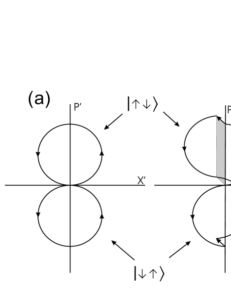
is the same for the and states and proportional to the encircled phase-space area. Figure 6a shows an example for the trajectory traversed in phase space during an ideal gate in a reference frame rotating at the mode frequency .
In the presence of laser light there is a finite probability that a Rayleigh photon will be scattered by one of the ions during the gate multiple scattering remark .
The probability for a Rayleigh scattering event to occur during a single-qubit gate is given by the difference between Eq. (4) and Eq. (13)
| (36) |
Since in the limit of all scattering events are Rayleigh scattering, and have the same asymptotic value .
Using Eq. (36) and the factor for the extra required power in the two-qubit gate
| (37) |
The effect on the ion motion would be that of momentum recoil
| (38) |
Here is the wave vector difference between the scattered photon and the laser beam from which it was scattered, and is the position operator of the ion that scattered the photon (). We will neglect recoil into directions other than along the trap axis. We can write the position operator for for ion along this axis as
| (39) |
where is the equilibrium position of the ion and , and are the root mean-square of the ground state spatial spread, and the creation and annihilation operators, respectively, of the two motional modes and . We assume the gate is performed by exciting mode . Recoil into mode does not distort the gate dynamics directly. This part of the photon recoil will add minutely to the gate error through its contribution to the gate nonlinearity discussed in section III.2. We neglect this contribution for the moment and write the recoil operation as
| (40) |
where is the projection of along the trap axis, and .
The recoil action on the two-ion crystal is, therefore, a momentum displacement in phase space. The magnitude of depends on the wave-vector difference between the scattered photon and the beam from which it was scattered, and the projection of this momentum difference along the trap axis. Since the same recoil displacement is applied to all spin states, motion will still be disentangled from spin at the end of the gate. Errors are therefore due to the change in area encircled in phase space. Figure 6b illustrates a gate trajectory that is distorted due to photon recoil.
The erroneous gate can be again written as a sum of displacements, those due to the gate drive and , which occurs at some random time during the gate. For a particular two-ion spin state,
| (41) |
By use of the commutation relation (32), the gate is written as
| (42) |
where the phase error is determined to be
| (43) |
Writing displacements as a function of the gate time
| (44) |
we can write the phase error as a function of the gate displacement before and after the scattering time
| (45) |
Since we get
| (46) |
Since the accumulated displacement at the moment the photon was scattered is of equal magnitude but opposite sign for the and states, we get
| (47) |
The erroneous gate can be therefore represented by the operator
| (48) |
The final state fidelity following the erroneous gate depends on . For a general initial state
| (49) |
and using Eq. (7), we can write for the gate fidelity
| (50) |
The most relevant fidelity for fault tolerance considerations is that averaged over all possible initial states. The fidelity we calculate here is that due to the worst-case input state, that is the input state that minimizes Eq. (50). The worst-case fidelity is clearly smaller than the average fidelity and therefore gives a conservative estimate to the gate error worstcase_vs_average . The worst-case fidelity for this kind of error was calculated in Sasura_Steane . For it is
| (51) |
This minimal fidelity is the result of an input state with .
Photon scattering occurs in only a small fraction of the gates. Averaging over all gates performed, we get
| (52) |
where the brackets correspond to an average over all possible ’s, i.e. due to different values of and different scattering times.
To perform the above average we need to explicitly write the different displacements. In the rotating frame the cumulative gate displacement after a time can be written as Didi_gate ; SMgate
| (53) |
where is the gate phase, determined by the optical phase difference between the gate beams at the ion’s position. In the rotating frame, the recoil displacement can be written as
| (54) |
Substituting equations (54) and (53) into Eq. (46), we can write the averaged term in the fidelity
| (55) |
Here we assume that the probability of scattering at different time intervals during the gate is uniform. The probability distribution for different recoil displacement magnitude is given by , which is determined by the geometry of the Raman beams with respect to the trap axis and the probability distribution of photon scattering directions.
With the laser beam configuration assumed in Fig.(4), recoil due to photon absorption can be imparted only at to the trap axis, whereas recoil due to photon emission can be imparted in any direction. The maximum allowed displacement following an absorption-emission cycle is therefore
| (56) |
For proper gate operation we require ; thus we expand Eq. (55) in powers of , including terms to order . Further, since typically , we neglect terms proportional to . With these approximations the gate fidelity is independent of and is given by
| (57) |
Here is the average of the recoil displacement magnitude squared
| (58) |
For the assumed laser beam configuration, the light field polarization will oscillate rapidly during the gate between left/right circular and linear at the ions’ position. Therefore, the scattering probability will average to be isotropic. For the beam configuration illustrated in Fig.4, in spherical-polar coordinates,
| (59) |
Here the () direction is chosen parallel to the trap axis. We find
| (60) |
Combining Eqs. (52), (57), (60) and (37), the Rayleigh error can be written as
| (61) |
The ratio of to is therefore
| (62) |
Table 4 lists for different ion species for =5 MHz, and a single-circle (=1) gate, at a detuning where . For most ions considered here, the gate error is still dominated by Raman scattering at this level.
For laser beam detuning large compared to the excited state fine-structure splitting () scattering is dominated by Rayleigh events. In this limit, the probability that a Rayleigh photon will be scattered during the gate is
| (63) |
The recoil error in a two-qubit gate is therefore asymptotically bound by
| (64) |
Table 4 lists for different ion species for =5 MHz and a single-circle (=1) gate. With the exception of 9Be+, the error due to photon recoil in a two ion-qubit gate is below . For this error heavier ions benefit due to their smaller recoil.
It is possible to reduce by choosing a smaller (by increasing the trap frequency and/or performing multiple-circles gates). Correspondingly more laser power, proportional to , is then required in order not to increase the Raman scattering error or reduce the gate speed.
| Ion | ||
|---|---|---|
| 9Be+ | 1.442 | 1.51 |
| 25Mg+ | 0.142 | 0.154 |
| 43Ca+ | 0.0168 | 0.0187 |
| 67Zn+ | 0.0172 | 0.0193 |
| 87Sr+ | 0.0030 | 0.0034 |
| 111Cd+ | 0.0040 | 0.0044 |
| 137Ba+ | 0.0010 | 0.0011 |
| 171Yb+ | 0.0006 | 0.0006 |
| 199Hg+ | 0.0015 | 0.0012 |
III.2 Other Rayleigh scattering errors
In section III.1 we calculated the error due to the recoil imparted to the ion-qubit during Rayleigh photon scattering. As noted, Rayleigh scattering of photons adds two more contributions to the gate error.
The first contribution is due to a difference in the Rayleigh scattering rates from the two ground state levels. Assume that the Rayleigh scattering rate is from one qubit level and from the other. A measurement of the qubit level will be conclusive once the difference in the number of photons that are scattered is larger than the standard deviation of the number of photons scattered from each level. Since the number of photons that are scattered follows a Poisson distribution, a measurement will occur after photons have been scattered for a time such that
| (65) |
The error rate is, therefore, given by , and the error during a gate by
| (66) |
For the above gate parameters, the difference in scattering rates is due solely to the difference in detuning between the two qubit levels. For , which is typically required to reduce other scattering errors to low levels, this error can be approximated by . The contribution of to the total error at a realistic laser detuning is very small. We performed an accurate calculation of the difference in the scattering rates between the two clock levels, and verified that indeed, for all ion species and laser detunings discussed above, is negligible.
A second source of Rayleigh scattering error is through the contribution of the recoil momentum displacement to non-linearities in the gate evolution. The gate error due to non-linearities was calculated in SMgateThermal and in the present context is proportional to , where is the variance of the motional modes distribution due to recoil. The recoil momentum displacement magnitude is of order . Therefore, starting from the ground state and following a single scattering event, . The gate error due to this effect will be proportional to , and significantly smaller than other scattering errors discussed above.
IV DISCUSSION
We have calculated the errors due to photon scattering in a single-pulse single-qubit gates and two-qubit phase-gates implemented with stimulated Raman transitions. These errors present a fundamental limit to the gate fidelity in trapped-ion QIP experiments that use these kinds of gates, and should be a significant factor when choosing a specific ion as a quantum information carrier for fault-tolerant quantum computing schemes.
Three main errors occur from spontaneously scattering photons during a gate. Two errors are due to Raman scattering either back into the manifold () or to low-lying D levels (). The third error is due to the Rayleigh scattering recoil during a two-qubit gate (). For most ions currently considered for QIP experiments, the dominant error for realistic laser parameters is . This error can be typically reduced to below current estimates for the fault-tolerance threshold with the use of relatively high (but probably attainable) laser power. This makes the availability of high power laser sources at the relevant wavelength important. This error is also reduced for ions with a relatively large transition wavelength.
Among those three errors, only cannot be reduced below a certain value by the use of higher laser intensity. Therefore, it may eventually be advantageous to choose ions that do not have low lying D levels. However, for most ions considered here, is still small at realistic laser parameters compared to the other Raman error .
The masses of the different ions play an interesting role in the scattering error. Since it is harder to transfer momentum to heavier ions, they suffer from a larger in two-qubit gates (or alternatively from the need for more laser power for a given gate speed and error level). For the same reason, lighter ions suffer from a larger Rayleigh recoil error . Examining Eqs. (28) and (64), the Raman error scales as and the Rayleigh error scales as (neglecting differences in wavelength and natural linewidths). Since both and are generally larger for heavier ions, the Raman error is larger and Rayleigh error is smaller for heavier ions by more than is indicated by the kinetic argument above. Since for most ions is the dominant error, lighter ions seem to currently have a lower overall error due to photon scattering. Also, because both errors are a function of lighter ions will reach the same error level and power requirements with a higher when compared to heavier ions. This allows for faster gate operation. For a given trap geometry and applied potentials, the axial trap frequency scales as and the radial trap frequencies scale as . For the ion crystal to remain along the axial trap direction the radial frequencies have to be larger than the axial frequencies; therefore the limiting frequency is the radial frequency. In this case, is independent of the ions’ mass. Heavier ions under these conditions will have a lower , leading to slower gate operation.
In conclusion, to minimize the effect of scattering on the fidelity of trapped-ion-qubit gates, one needs to strike a balance between the desirable characteristics of long wavelength, light mass, the availability of high power laser sources and, if possible, the lack of low lying D levels when choosing a specific ion as a quantum information carrier.
Finally, we remind the reader that here we have focused on hyperfine ion-qubits and gates that rely on off-resonant Raman transitions applied in a continuous pulse. Other kinds of trapped-ion gates or qubits could have different limitations on the gate fidelity due to spontaneous photon scattering.
We thank E. Knill for many insightful discussions and comments, J. Home, J. Amini and A. Sørensen for helpful comments. This work is supported by DTO and NIST. Contribution of NIST; not subject to US copyright.
Appendix A Dephasing vs. entanglement with different photon modes
In section III we calculated the error due to Rayleigh photon scattering without considering the scattered photon degrees of freedom. Rather, we considered dephasing due to the random phase that is generated by the scattered photon’s recoil.
As noted, we can also view the gate error caused by Rayleigh scattering of photons as arising from the entanglement between the photon and the ion-qubit external degrees of freedom. For example, a photon that is scattered during the gate, while the two spin wave packets are displaced from each other, can be collected by an ideal imaging system. Since the two-ion collective spin is entangled with their position, the position at which the photon is detected at the image plane can give “which-way” information, thereby measuring the ions’ spin, collapsing the entanglement, and causing an error in the gate. Experiments investigating atomic decoherence due to this effect were performed in neutral-atom interferometers Pritchard95 ; Weitz01 . This effect was also calculated in Feagin06 for a single ion in a superposition of two different motional coherent states.
The general equivalence of these two points of view (dephasing vs. entangling with the environment) was explained in Stern90 . Here we show this equivalence for the trapped ion case where the ion is undergoing an (ideally) spin-dependent closed loop displacement. For simplicity we examine the case of a single ion; it is, however, straightforward to generalize the following proof to the case of two ions.
We first calculate the final state fidelity by examining entanglement with the photon modes. As in the two-qubit gate, a single ion is prepared in an equal superposition of spin states and is cooled to the motional ground state:
| (67) |
Here kets with subscript represent motional states, and kets with the subscript k the different photon modes, which are initially empty (neglecting the laser mode). The ion is subsequently driven by an oscillating force which is detuned from its motional resonance. The direction of force is opposite for the two different spin states. Ideally the two spin states would traverse opposite circular trajectories in phase space (in a frame rotating at the motional mode frequency). At the end of the gate drive, both parts of the superposition (ideally) return to the ground state of motion, and acquire the same geometric phase which is proportional to the phase-space area encircled. The state at the end of the ideal gate drive is
| (68) |
Now assume the ion scattered a photon during the gate drive. Immediately before the scattering event, the gate evolution produces
| (69) |
where are the conditional phase-space displacement for the two spin states (we have dropped the subscript ) and is the geometric phase accumulated by the time of scattering. Immediately after scattering, a single photon is created in mode k’ and the ion correspondingly recoils:
| (70) | |||
Here is the wave vector difference between the scattered photon and the laser beam. The delta-function enforces energy conservation. The electromagnetic field is now represented by a superposition of states in which a single photon was scattered into a certain mode while all other modes are empty. Each part of this superposition is correlated with the corresponding momentum recoil operator acting on the trapped ion. Recoil into directions other than the trap axis will give rise to motion which is common to both parts of the superposition, and can therefore be traced over. We, therefore, neglect recoil into the dimensions other than the trap axis direction, and approximate , where . By use of Eq. (40) this momentum recoil can be written as a phase space displacement , where , and is the root mean-square of the ground state spatial spread. Using Eq. (32) we add the recoil to the gate displacement and the state after scattering can be written as
| (71) | |||
Since the total gate displacement is equal to zero, the remaining part of the gate displacement is (depending of the spin state). Using Eq. (32) again, we can write the state of the system after the gate has completed
| (72) | |||
We can now define the gate phase-error , and write the corresponding density operator
| (73) | |||
Since we have no information about the mode into which the photon was scattered, we reduce the above density matrix with a trace over the photon modes, using ,
| (74) |
Note that the coherences of the density matrix in Eq. (74) are given by an average of . A large spread in will “wash-out” coherence and leave an incoherent statistical mixture. Tracing over the motional degrees of freedom we are now ready to evaluate the fidelity with respect to the ideal gate output state (Eq. (68)).
| (75) |
where averaging is performed with respect to all of the photon modes:
| (76) |
We now turn to calculate the fidelity looking only at dephasing as in Sec. III.1, i.e. loss of fidelity due to the photon scattering random phase. The gate output state is then
| (77) |
where is the random scattering phase (Eq. 46). The fidelity of this state with respect to the ideal gate output state is identical to that calculated considering entanglement with the photon modes in Eq. (75).
References
- (1) J. I. Cirac and P. Zoller, Phys. Rev. Lett. 74, 4091 (1995).
- (2) D. J. Wineland et. al., J. Res. Nat. Inst. Stand. Tech. 103, 259 (1998).
- (3) Ch. Wunderlich and Ch. Balzer, Adv. At. Mol. Opt. Phys. 49, 293 (2003).
- (4) C. Langer et. al., Phys. Rev. Lett. 95, 060502 (2005).
- (5) D. Lucas, private communication.
- (6) D. Leibfried et. al., Nature 438, 639 (2005).
- (7) H. Häffner et. al., Nature 438, 643 (2005).
- (8) C. A. Sackett et. al., Nature 404 256 (2000).
- (9) D. Leibfried et. al., Nature 422, 412 (2003).
- (10) F. Schmidt-Kaler et. al., Nature 422, 408 (2003).
- (11) P. C. Haljan et. al., Phys. Rev. A 72, 062316 (2005).
- (12) J. P. Home et. al., New J. Phys. 8, 188 (2006).
- (13) J. J. Bollinger et. al., IEEE Trans. Instrum. Measurement 40, 126 (1991).
- (14) P. T. H. Fisk, M. J. Sellars, M. A. Lawn, C. Coles, A. G. Mann, and D. G. Blair, IEEE Trans. Instrum. Meas. 44, 113 (1995).
- (15) A. M. Steane, Phys. Rev. A 68, 042322 (2003).
- (16) B. W. Reichardt, arXiv:quant-ph\0406025 (2004).
- (17) E. Knill, Nature 434, 39 (2005).
- (18) M. B. Plenio and P. L. Knight, Proc. R. Soc. Lond. A 453 2017 (1997).
- (19) B. R. Mollow, Phys. Rev. A 12, 1919 (1975).
- (20) S. Schneider and G. J. Milburn, Phys. Rev. A 57, 3748 (1998).
- (21) W. M. Itano, Phys. Rev. A, 68, 046301 (2003).
- (22) A. Silberfarb and I. H. Deutsch, Phys. Rev. A 69, 042308 (2004).
- (23) D. J. Wineland et. al., Phil. Trans. R. Soc. Lond. A 361 1349 (2003).
- (24) R. A. Cline, J. D. Miller, M. R. Matthews and D. J. Heinzen, Opt. Lett. 19 207 (1994).
- (25) R. Ozeri et. al., Phys. Rev. Lett. 95,030403 (2005).
- (26) J. Gea-Banacloche, arXiv:quant-ph/0504187 (2005).
- (27) Here we assume, that is the same for the and the levels. This is a reasonable assumption for most ions considered. For the heavier ions in Table 1 the difference can be to . The values for given in the table and used in the calculations are those of the level.
- (28) T. Andersen, K. A. Jessen, and G. Sørensen, Phys. Rev. 188, 76 (1969).
- (29) W. Ansbacher, Y. Li and E. H. Pinnington, Phys. Lett. A 139, 165 (1989).
- (30) R. N. Gosselin, E. H. Pinnington and W. Ansbacher,Phys. Rev. A 38, 4887 (1988).
- (31) R. Mayo, M. Ortiz and J. Campos, Eur. Phys. J. D. 37, 181 (2006).
- (32) E. H. Pinnington, R. W. Berends and M. Lumsden, J. Phys. B 28, 2095 (1995).
- (33) D. L. Moehring et. al., Phys. Rev. A 73, 023413 (2006).
- (34) E. H. Pinnington, G. Rieger and J. A. Kernahan, Phys. Rev. A 56, 2421 (1997).
- (35) E. H. Pinnington et. al., Can. J. Phys. 66, 960 (1988).
- (36) D. J. Wineland, J. J. Bollinger, J. M. Itano, Phys. Rev. Lett. 50, 628 (1983).
- (37) W. M. Itano and D. J. Wineland, Phys. Rev. A 24, 1364 (1981).
- (38) F. Arbes et. al., Z. Phys. D 31, 27 (1994).
- (39) S. N. Panigrahy, R. W. Dougherty, T. P. Das and J. Andriessen, Phys. Rev. A 44, 121 (1991).
- (40) H. Sunaoshi et. al., Hyperfine Interact. 78, 241 (1993).
- (41) U. Tanaka et. al., Phys. Rev. A 53, 3982 (1996).
- (42) R. Blatt and G. Werth, Phys. Rev. A 25, 1476 (1982).
- (43) R. Blatt, H. Schnatz and G. Werth, Phys. Rev. A 48, 1601 (1982).
- (44) D. J. Berkeland et. al., Phys. Rev. Lett. 80, 2089 (1998).
- (45) http://physics.nist.gov/PhysRefData/ASD/
- (46) The photon density of states and, hence, the scattering rate will change as the emission wavelength varies with the laser detuning. For most ions considered the fine-structure splitting is small compared to the distance between the and the levels and therefore this will be a small effect. This is not the case however for 199Hg+ and 171Yb+, and therefore for these ions this evaluation of is only approximate.
- (47) In situations where the detuning is not large compared to it would be more accurate to average the branching ratios of the two P levels with weights corresponding to their excitation probaility. For most ions considered here (excluding 199Hg+ and 171Yb+) the difference in branching ratios is small; we, therefore, take a non-weighted average.
- (48) A. Gallagher, Phys. Rev. 157, 24 (1967).
- (49) W. M. Itano, J. C. Bergquist, R. G. Hulet and D. J. Wineland, Phys. Rev. Lett. 59, 2732 (1987).
- (50) A. Gallagher, Phys. Rev. A 11, 1223 (1975).
- (51) C. Roos, Ph.D. Thesis, Universität Innsbruck (2000).
- (52) G. Werth, Metrologia 22, 190 (1986).
- (53) A. Sørensen and K. Mølmer, Phys. Rev. Lett. 82, 1971 (1999).
- (54) E. Solano, R. L. de Matos Filho, and N. Zagury, Phys. Rev. A 59, R2539 (1999).
- (55) G. J. Milburn et. al., Fortschr. Phys. 48, 9, 801 (2000).
- (56) J. J. García-Ripoll, P. Zoller and J. I. Cirac, Phys. Rev. Lett. 91, 157901 (2003).
- (57) P. J. Lee et. al. J. Opt. B 7, S371 (2005).
- (58) For realistic parameters ; therefore we neglect the possibility that more than one photon is scattered during the gate.
- (59) We assume that the distance between the ions is large compared to the wavelength of light. Therefore, scattering events of the two ions are not correlated.
- (60) Since the off-resonant coupling to the carrier scales as , even with our choice of constant lighter ions suffer less from errors due to this coupling. Furthermore, lighter ions require lower RF trap potentials for the same .
- (61) A. Sørensen and K. Mølmer, Phys. Rev. A 62, 022311 (2000).
- (62) For a small phase-error, the error averaged over all possible input states is a factor of 2 lower than the worst-case input error.
- (63) M. Šašura and A. M. Steane, Phys. Rev. A. 67, 062318 (2003).
- (64) M. S. Chapman et. al., Phys. Rev. Lett. 75, 3783 (1995).
- (65) M. Mei and M. Weitz, Phys. Rev. Lett. 86, 559 (2001).
- (66) J. M. Feagin, Phys. Rev. A 73, 022108 (2006).
- (67) A. Stern, Y. Aharonov and Y. Imry, Phys. Rev. A 41, 3436 (1990).