Laboratoire Kastler Brossel, CNRS, ENS, UPMC case 74, Campus Jussieu, 75252 Paris, France
Quantum optics Theory of quantized fields Interface structure and roughness
Vacuum induced torque between corrugated metallic plates
Abstract
We study the torque arising between two corrugated metallic plates due to the interaction with electromagnetic vacuum. This Casimir torque can be measured with torsion pendulum techniques for separation distances as large as 1m. It allows one to probe the nontrivial geometry dependence of the Casimir energy in a configuration which can be evaluated theoretically with accuracy. In the optimal experimental configuration, the commonly used proximity force approximation turns out to overestimate the torque by a factor 2 or larger.
pacs:
42.50.-ppacs:
03.70.+kpacs:
68.35.CtThe Casimir effect [1] plays a major role in micro- and nano-electromechanical systems (MEMS and NEMS) [2]. Besides the normal Casimir force between metallic or dielectric plates [3], the observation of the lateral Casimir force between corrugated plates [4] opens novel possibilities of micro-mechanical control. The lateral force results from breaking the translational symmetry along directions parallel to the plates by imprinting periodic corrugations on both metallic plates. As rotational symmetry is also broken by this geometry, a Casimir torque should also arise when the corrugations are not aligned. In the present letter, we study this effect which provides one with a new mechanism of micro-mechanical control to be exploited in the design of MEMS and NEMS.
From the point of view of fundamental physics, this effect makes possible an accurate investigation of the non-trivial geometry dependence of the Casimir energy. Tests of this geometry dependence performed up to date have often been limited by the use of the proximity-force approximation (PFA) in the calculations [5]. Within this approximation, the energy is evaluated by simply averaging the Casimir energy between two planes over the distribution of local distances, which is certainly insufficient except for the limiting case of large corrugation wavelengths [6]. Other calculations [7] have gone farther than PFA while using a model of perfect reflection, which limited their validity to experiments performed with metallic mirrors at distances larger than a few m.
Here we use the scattering approach [8, 9] extended to treat non-planar surfaces [10, 11]. This perturbative approach is restricted by the assumption that corrugation amplitudes are smaller than other length scales but it allows one to go beyond the range of validity of the PFA, with arbitrary values of the corrugation wavelengths with respect to plate separation and plasma wavelength of the metal. As shown below, it accurately describes configurations which are experimentally testable and where the Casimir energy has a non-trivial geometry dependence. This new effect induced by vacuum fluctuations may be small because the corrugation amplitudes are small, but the torque detection is particularly interesting from this point of view, since it allows one to use the exquisite sensitivity of torsion balances [12].
The idea of using torsion techniques has already been proposed to measure Casimir torques between anisotropic dielectric plates [13, 14, 15, 16]. Recently, an experiment has been proposed to measure the torque with a birefringent disk on top of a barium titanate plate [17]. According to the authors, the proposed measurement is feasible at a plate separation of 100nm. We show below that the torque between corrugated metallic plates is up to three orders of magnitude larger than the torque between anisotropic dielectric plates, for comparable values of the separation distance and plate area. With realistic values for the corrugation amplitudes and and wavelength , we conclude that the torque measurement may be done at a distance of the order of 1m. This minimizes the spurious effects due to the non-parallelism of the plates while making the contribution of interband transitions negligible. We thus model the finite conductivity of the metallic plates by the plasma model with a plasma wavelength . We calculate the modification of the Casimir energy up to second order in the corrugation amplitudes assumed to be smaller than other length scales
| (1) |
This condition, allowing us to use perturbation theory, will be satisfied by the numerical examples discussed below.
The surface profile functions for the two plates are denoted as with labeling the two plates. They define the local heights, counted as positive when corresponding to separation decreases with respect to reference planes at and . Both have zero spatial averages, so that represents the average separation distance between the two surfaces, and collects the two transverse coordinates defining the position on the plates. The corrugated surfaces are described by non-specular reflection coefficients that couple different field polarizations and momenta [18]. The second-order correction is then given by [11]
| (2) |
where is the Fourier transform of . The response function does not depend on the direction of the corrugation wavevector It is given in [11] as a function of the specular and non-specular reflection coefficients. Only the crossed terms of the form are kept in eq. (2), since terms quadratic in and in do not depend on the relative angle between the plates, and hence do not contribute to the torque.
We assume the corrugations to have sinusoidal shapes with corrugation wavevectors having the same modulus . The angle between and represents the angular mismatch between the two corrugations and is supposed, for convenience, to be aligned along the direction of the axis. The parameters represent lateral displacements with respect to the configuration with a line of maximum height at the origin. With these conventions, eq. (2) yields
| (3) |
The integral yielding may be specified by considering that the corrugation is restricted to a rectangular section of area centered at We assume that both and are much larger than so that diffraction at the borders of the plates is negligible. The energy correction per unit area is then given by
| (4) | |||||
| (5) |
is the relative lateral displacement along the direction of ; as expected by symmetry, the energy does not depend on displacements perpendicular to . Eq. (4) satisfies reflection symmetry around the and directions (invariance under the transformations and ), which results from the fact that the corrugation lines have no orientation. It contains as a special case () the result for pure lateral displacement derived in Ref. [11].
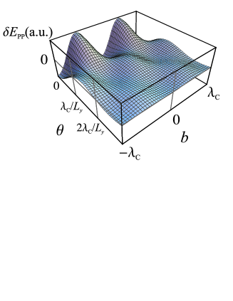
The energy variation with and given by eq. (4) is universal, since the separation distance and additional parameters characterizing the metallic surfaces determine only the global pre-factor In the limit of long corrugation lines, we may take the approximation in eq. (4), since is negligible otherwise. If is smaller or of the order of we find from eq. (4)
| (6) |
Hence, the scale of variation of is set by the parameter
In Fig. 1, we plot (in arbitrary units) as a function of and Since is negative [11], the Casimir energy is minimum at and corresponding to the geometry with aligned corrugations and the local separation distance having the maximum variation amplitude. There are also shallow wells around (minimum of ) and If we start from and rotate plate 2 around its center, we follow the line in Fig. 1. This figure shows that for small angles the plate is attracted back to without sliding laterally. On the other hand, if the plate is released after a rotation of its subsequent motion will be a combination of rotation and lateral displacement. In fact, the energy correction vanishes at , defining the range of stability of the configuration Rotation is favored over lateral displacements for
We now proceed to an evaluation of the torque which is given by
| (7) |
It is maximum at where it is given by
| (8) |
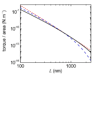
As could be expected, this maximal torque per unit area is proportional to the length of the corrugation lines, which provides the scale for the moment arm. In order to plot the value of the torque (8) on Fig. 2, we take the plasma wavelength corresponding to gold for both plates (nm). We chose corrugation amplitudes obeying condition (1) and leading to (to be compared with in the lateral force experiment [4], where and were unequal) and m. Different values for and can also be derived from these results through a mere multiplication by suitable pre-factors (see eq. 8), provided that these values satisfy and The first condition is at the heart of our perturbative approach, whereas the second condition can be relaxed by going back to the more general result (4).
The dashed line in Fig. 2 corresponds to the corrugation period of the lateral force experiment [4]. At we find in this case , approximately three orders of magnitude larger than the torque per unit area for anisotropic plates calculated in Ref. [17] for the most favorable configuration at the same separation distance. The much larger figures found in our case should certainly allow one to perform the experiment at larger separation distances. For Fig. 2 shows that the torque for starts to decrease exponentially. However, by selecting longer corrugation periods, one also finds measurable orders of magnitude in this range of distances.
At any given value of , the torque between corrugated plates can be made larger by chosing the corrugation period so as to maximize In the range of separation distances shown on Fig. 2, this corresponds to or . The torque is thus given by the dotted line, which provides upper bounds for its magnitude. At the optimum value is corresponding to the solid line in Fig. 2. In this case, we find As for the relevant angle scales, the stability threshold is at and the maximum torque at If rotation is to be observed from the position of the tip of the rectangular plate, then the relevant parameter is the arc described by the tip which is independent of
Under such optimum conditions, the torque probes a non-trivial geometry dependence of the Casimir energy, since the PFA thus grossly overestimates the effect, as shown now. The PFA holds for smooth surfaces corresponding to the limit It is recovered from eq. (8) at the limit , where the response function satisfies the general condition [11] where is the Casimir energy per unit area for parallel planes. In this limit, the effect of geometry is trivial because the PFA directly connects the non-planar geometry to the more commonly studied configuration of parallel planes. We thus find a result determined by the Casimir energy for this simpler geometry:
| (9) |
In order to compare with the PFA, we plot our results for the torque as a function of for in Fig. 3 (solid line), and with all other parameters as in Fig. 2. As discussed above, the torque is maximum at We also show the values obtained from the model with perfect reflectors (dashed line). They overestimate the torque by near the peak region.
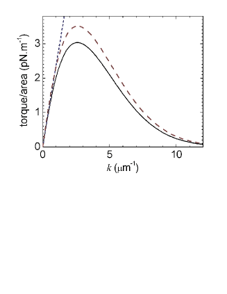
According to eq. (9), the torque grows linearly with in the PFA (dotted line). It is thus worth increasing the value of and hence going out the region of validity of PFA. At the peak value the PFA overestimates the torque by As the torque decays for larger values of the PFA rapidly becomes less and less accurate. The discrepancy is measured by the ratio
| (10) |
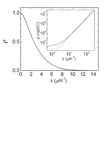
At the exact and PFA values coincide (). For as in the numerical example of Fig. 4. Thus, the PFA always overestimates the torque and the discrepancy increases with as expected, since smaller values of correspond to smoother surfaces.
For and decay exponentially to zero. Such behavior has a simple interpretation within the scattering approach [11]. The reflection by the corrugated surfaces produce lateral wavevector components of the order of After replacing the integral over real frequencies by an integral over the imaginary axis in the complex plane, we obtain propagation factors, representing one-way propagation between the plates, of the order of
In order to analyze the large- behavior in more detail, we plot in the inset of Fig. 4. In the intermediate range approaches the high- limit of the model with perfect reflectors [7], drawn as the dashed line in the inset of Fig. 4,
| (11) |
As approaches stays more and more below the result for perfect reflectors, reaching the following limit for very large values of (not shown on the figure),
| (12) |
Thus, the perfect-reflecting regime is reached only when the plasma wavelength is the shortest length scale in the problem (apart from the corrugation amplitudes). Just taking the limit is not sufficient for recovering the limit of perfect reflectors [7]. This has again a very simple interpretation in the scattering approach. When the relevant input field modes are perfectly reflected because they have wavevectors of order of However, diffraction by the corrugated surfaces produces wavevectors of the order of which are poorly reflected by the plates if
In conclusion, we have studied the torque induced by vacuum fluctuations between corrugated metallic plates. This Casimir torque may provide one with a new mechanism of micro-mechanical control to be exploited in the design of MEMS and NEMS. It could as well be a new observable of interest to test the geometry dependence of the Casimir energy. We recover the PFA from our theory in the limit but deviations become rapidly important as is increased.
The torque is up to three orders of magnitude larger than the torque between anisotropic dielectric plates for comparable distance and area. This should allow for an experimental observation of the Casimir torque at separation distances around m, using corrugation periods of the same order of magnitude (). In this configuration, the PFA grossly overestimates the torque by a factor of the order of 2. Moreover, it predicts an algebraic decay of the torque as is increased past the optimum value, whereas the exact decay is actually exponential. This experiment would provide, for the first time, direct evidence of the nontrivial geometry dependence of the Casimir effect.
Acknowledgements.
R.B.R. and P.A.M.N. thank O. N. Mesquita for discussions and FAPERJ, CNPq and Institutos do Milênio de Informação Quântica e Nanociências for financial support. A.L. acknowledges partial financial support by the European Contract STRP 12142 NANOCASE.References
- [1] CASIMIR H. B. G., Proc. K. Ned. Akad. Wet., 51 (1948) 793.
- [2] CHAN H. B., AKSYUK V. A., KLEIMAN R. N., BISHOP D. J. and CAPASSO, F., Science, 291 (2001) 1941.
- [3] KLIMCHITSKAYA G. L. et al, J. Phys. A: Math Gen. 39 (2006) 6485 and references therein.
- [4] CHEN F., MOHIDEEN U., KLIMCHITSKAYA G. L. and MOSTEPANENKO V. M., Phys. Rev. Lett. 88 (2002) 101801; Phys. Rev. A 66 (2002) 032113.
- [5] DERIAGIN B. V., Kolloid Z. 69 (1934) 155; DERIAGIN B. V., ABRIKOSOVA I. I. and LIFSHITZ E. M., Quart. Rev. 10 (1968) 295.
- [6] GENET C., LAMBRECHT A., MAIA NETO, P. and REYNAUD S., Europhys. Lett. 62 (2003) 484 .
- [7] EMIG T., HANKE A., GOLESTANIAN R. and KARDAR M., Phys. Rev. A 67 (2003) 022114.
- [8] GENET C., LAMBRECHT A. and REYNAUD S., Phys. Rev. A 67 (2003) 043811.
- [9] LAMBRECHT A., MAIA NETO P. A. and REYNAUD S., submitted (2006).
- [10] MAIA NETO, P. A., LAMBRECHT A. and REYNAUD S., Phys. Rev. A 72 (2005) 012115 .
- [11] RODRIGUES R. B., MAIA NETO P. A., LAMBRECHT A. and REYNAUD S., Phys. Rev. Lett. 96 (2006) 100402.
- [12] GUNDLACH J.H., Meas. Sci. Technol. 10 (1999) 454.
- [13] PARSEGIAN V. A. and WEISS G. H., J. Adhes. 3 (1972) 259.
- [14] BARASH Y., Izv. Vyssh. Uchebn. Zaved., Radiofiz. 12 (1978) 1637;.
- [15] van ENK S. J., Phys. Rev. A 52 (1995) 2569.
- [16] TORRES-GUSMÁN J. C. and MOCHÁN W. L., J. Phys. A: Math Gen. 39 (2006) 6791.
- [17] MUNDAY J. N., IANNUZZI D., BARASH Y. and CAPASSO F., Phys. Rev. A 71 (2005) 042102.
- [18] Whereas the method developed in Ref. [7] requires the existence of a direction of translational symmetry (so as to allow for the definition of field polarizations conserved in the scattering by the surfaces), our approach allows for the calculation in a geometry with no such symmetry, such as the rotated corrugated plates, because it explicitly takes into account the coupling between different polarizations.