Interference of quantum channels in single photon interferometer
Abstract
We experimently demonstrate the interference of dephasing quantum channel using single photon Mach-Zender interferometer. We extract the information inaccessible to the technology of quantum tomography. Further, We introduce the application of our results in quantum key distribution.
pacs:
42.50.Lc ; 42.25.HzMacroscopic quantum systems can never be isolated from their environments. It leads to decoherence which destroys superpositions. And when a qubit transmits through a quantum channel, the interaction between qubit and quantum channel is inevitable. The decoherence in quantum channel affects the distance and quantity of quantum information transmitting. So it is important to know what happen when quantum information transmit through noisy quantum channel. The technology of quantum process tomographyChilds01 ; Jezek02 can be used to character the quantum channels.
But J. Abergaberg03 find that we can not specify the action of the sinultaneous operation of both maps although we known the individual quantum channels. It is said that when a superposition state pass through two quantum channels, we can not know the information of output state exactly by using the technology of quantum process tomography. Single particle interference can help us extract information inaccessible to conventional process tomography. D. K. L. Oi have given a measure of coherent fidelity, the maximum interference visibility, and the closest unitary operator to a given physical process under this measuredan03 .
Here, We give an interference visibility of two quantum processes which have same environment degree and carry out an experiment to demonstrate it. The environment qubit is the time qubit from birefrigence of quartz crystal in the experiment, i.e. quantum channels we used is the dephasing channel. We find that there are plentiful information of inteference which is the information inaccessible to conventional process tomographyChilds01 ; Jezek02 .
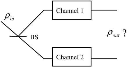
When a single qubit state transmits through two quantum channels (Fig. 1), how can we known the output state? The technology of quantum tomography can obtain the densities of output states in each paths. But the whole density of the output state can not be fixed, i.e. there is other information which have not been extracted. D. K. L. Oidan03 shows that single particle Mach-Zender inereference can help us. Different visibilities show quantum information not presented in the two individual quantum channel. When the different environment degree ( and ) appended to the operations of the upper and lower arms, D. K. L. Oi presents the interference patterns as
| (1) |
where is the input state, and are the first Kraus operators for the quantum processes and in upper and lower arms. If the input state is the maximally mixed state, the interference pattern depends on .
In Eq. 1, The interference patterns only depend on the first Kraus operators and . But it find that when the environment degree is same to the operations of the both arms (Fig. 2), the interference pattern will depend on the four Kraus operators and . The beamsplitters in Fig. 2 and the phase shifter are modeled by the unitary operators and respectively,
| (2) |
The original state of the system on internal Hilbert space and the two-dimensional Hilbert space of path degree is evolved as
| (3) |
where and represent the upper and lower path. The probability of finding the particle in the horizontal direction, i.e. in the state, is
| (4) |
So is decided by
| (5) |

where
| (6) |
are the Kraus operators of and . Where and are the orthornomal bases of E, is the initial state of E. Specially, If the input state is the maximally mixed state, the interference pattern depends on , which is the interference patterns of quantum channels.
So the interference patterns determined by all four kraus operators of and and their relative phase. It will give richer interference pattern than that Eq. 1 gives us.
The visibility of the intereference pattern is the effects of the indistinguishability of the two paths that the particle transmitted through. According to the intereference pattern and visibility, it can be determined whether the two quantum processes are identical or different (see ander03 for related problem). Because of the birefringence of ordinary light ( light) and extra-ordinary light ( light) in BBO crystal, we choose the time degrees of freedom of photon passing through a BBO crystal to be the environment qubit ( to for ordinary light and for extraordinary light). There are two birefrigence crystals in the upper and lower arms of Mach-Zender interferometer respectively (see Fig. 3). The Kraus operators of two arms can be represented by
| (7) |
Where , and are the angles of the fast axis of the crystals relative to horizontal direction; , and are orthogonal basis respectively. Here, are defined by the sequence of the four pulse following the second quartz crystal in the two arms respectively. For example, .
According to Eq. 4, the interference patterns are determined by
| (8) |
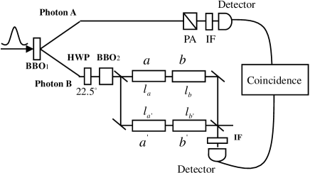
The experimental setup is represented in Fig. 3. A pulse of ultraviolet (UV) light pass through a BBO crystal (, cut for type-I phase match) . The UV pulse is frequency-doubled pulse (less than with repetition and center-wavelength) from a mode-locked Ti: sapphire laser (Tsunami by Spectra-Physics). Through the SPDC process, photon pairs are generated with center-wavelength. By detecting one photon of the pairs (with single photon detector after a FWHM interference filter at ), the other one (photon ) can be prepared into any polarization statekwiat03 ; xiang05 to be sent into Mach-Zender interferometer.
After a half-wave plate fixed and a thick BBO crystal (After which, the separation of wavepackets between H(o)- and V(e)-polarized light is about ) and Because the coherent length of the wavepacket is about ( FWHM interference filter is inserted before each detector), Photon is prepared in the maximally mixed state. Then it sent into Mach-Zender interferometer (Fig. 3). There are two quarz crystals in the upper and lower arms respectively. The two short ones () separate H(o)- and V(e)-polarized light (about ), and the two longer ones () separate H(o)- and V(e)-polarized light (about ). The angles of their

optical axes relative to horizontal plane are (see Fig. 3). Then beams from the two arms interact at the second beam splitter, and photon is detected by single photon detector below interferometer after a FWHM interference filter. The signals from two detectors are coincided within a timing window by using a coincidence counter (EG&G, TAC/SCA).
The maps according to quantum channel are changed by adjusting the angles ( and ) and the arrangement of four quartz crystals. we will observe the visibility of interference of different quantum channels. 1), we choose , , , and , then the visibility is which is always more than (Fig. 4a); 2), , , , and , then the visibility is (Fig. 4b); 3), , , , and , then the visibility is (Fig. 4c); 4), There is a half-wave plate in the upper and lower arms, i.e. , and the angles of the one in upper and lower arm are fixed in and respectively, then the visibility is (Fig. 4d). Because, to the maximally mixed states input, the outpt state are still maximally states after the quartz crystals in both arms and the fidelity of the output states of both arms are always which are independent of the maps in the armsxiang05 , the change of the visibilities according to is the information inaccessible to conventional process tomography.

Our results can be used to explain the low visibility of Mach–Zender interferometer in QKD system(mo05 ; mul97 ; boi04 ; hon04 ). A typical fiber QKD scheme is based on unbalanced fiber Mach–Zender interferometers (Fig. 5). Here we suppose the common quantum channel between two unbalanced Mach–Zender interferometers was identity. So this QKD system can be simplified to one Mach–Zender interferometer (see Fig. 3),and () correspond to four quartz crystals in our experiment. Eq. [5] gives the visibility of any input sate. Our further work will demonstrate the visibility of QKD scheme when the common quantum channel between two unbalanced Mach–Zender interferometers is not identity
In summary, we have demonstrated the interference of quantum channels single photon Mach-Zender interferometer. Our results present the information inaccessible to the techonology of quantum process tomography. This work can lead to further investigation into the phase between operations and structure and geometry of the CP maps.
The authors thank Zheng-Fu Han, Zheng-Wei Zhou and Yun-Feng Huang for interesting and helpful discussion. This research was funded by National Fundamental research Program (2001CB309300), the Innovation funds from Chinese Academy of Sciences KGCX2-SW-112 , and National Natural Science Foundation of China.
References
- (1) A. M. Childs, I. L. Chuang, and D. W. Leung, Phys. Rev. A 64, 012314 (2001)
- (2) M. Jezek, J. Fiurasek, and Z. Hradil, Phys. Rev. A 68, 012305 (2003).
- (3) J. Aberg, quant-ph/0302182
- (4) D. K. L. Oi, Phys. Rev. Lett. 91,067902 (2003)
- (5) E. Andersson, I. Jex, and S. M. Barnett, J. Phys. A 36, 2325 (2003)
- (6) P. G. Kwiat, J. B. Altepeter, D. A. Branning, E. R. Jeffrey, N. A. Peters, T. C. Wei, e-print quant-ph/0303040.
- (7) G. Y. Xiang, J. Li, B. Yu, and G. C. Guo, Phys. Rev. A 72 012315 (2005)
- (8) X. F. Mo, B. Zhu, Z. F. Han, Y. Z. Gui, and G. C. Guo, Optics Letter 30, 2632 (2005)
- (9) A. Muller, T. Herzog, B. Huttner, W. Tittel, H. Zbinden, and N. Gisin, Appl. Phys. Lett. 70, 793 (1997).
- (10) J. C. Boileau, D. Gottesman, R. Laflamme, D. Poulin, and R. W. Spekkens, Phys. Rev. Lett. 92, 017901 (2004)
- (11) T. Honjo, K. Inoue, and H. Takahashi, Opt. Lett. 29, 2797 (2004).