Experimental ancilla-assisted qubit transmission against correlated noise using quantum parity checking
Abstract
We report the experimental demonstration of a transmission scheme of photonic qubits over unstabilized optical fibers, which has the ability to transmit any state of a qubit, regardless of whether it is known, unknown, or entangled to other systems. A high fidelity to the noiseless quantum channel was achieved by adding an ancilla photon after the signal photon within the correlation time of the fiber noise and by performing a measurement which computes the parity. Simplicity, maintenance-free feature and robustness against path-length mismatches among the nodes make our scheme suitable for multi-user quantum communication networks.
pacs:
03.67.Pp, 03.67.Dd, 03.67.Hk1 Introduction
Quantum communication networks with many participants will provide various communication and computation tasks based on the nature of quantum physics, such as quantum key distribution[1, 2, 3], quantum teleportation[4], quantum repeaters[5], measurement-based quantum computing[6], and others[7, 8, 9]. Such a system inevitably involves manipulation of multi-partite entanglement, and requires faithful node-to-node transmission of an information carrier that is already entangled to other systems. Widespread use of such networks also demands a plug-and-play connectivity, which avoids the need for complicated stabilization and calibration tasks among distantly located users. Recent studies on practical quantum communication systems have mainly been focused on quantum key distribution (QKD). Among the most promising implementations for QKD are the plug-and-play schemes[10, 11, 12, 13, 14, 15, 16, 17] and those utilizing double Mach-Zender interferometers (MZI)[18, 19, 20], both of which share the common feature of robustness against correlated noise during transmission of quantum states in the optical fibers. In the plug-and-play systems based on the auto-compensation of birefringence effects during a round trip of light pulses[10, 11], the encoding of the transmitted states is done by choosing a manipulation on the incoming pulse, which implies that the transmitted state must be known to the sender. The plug-and-play feature can be also achieved by utilizing multi-photon entangled states in decoherence-free subspaces(DFS)[12, 13, 14, 15, 16, 17]. In this case, transmission of a photonic qubit in an unknown state requires an encoding process into multi-photon entangled states, which is difficult in the present technology. On the other hand, double MZI systems can be used for arbitrary quantum states whether it is known or unknown; however, the need for subwavelength-optical-delay adjustments in MZIs at each node stands as a disadvantage, especially when the number of the participants in the network increases. The existing schemes therefore lack either the plug-and-play feature or the ability to transmit a qubit that is in an unknown state or is entangled to other systems. Achieving both of the features at the same time is not only of practical importance but also of fundamental interest, since it amounts to a faithful transmission of quantum states between the parties who do not have the shared reference frame[21].
In this letter, we experimentally demonstrate such a faithful transmission scheme fulfilling both of the above requirements, for single-photon polarization states through optical fibers. This is achieved by adding an ancilla photon of a fixed polarization after the signal photon within the correlation time of the phase fluctuations in the fiber and by quantum parity checking. After the transmission of these photons through unstabilized optical fibres, the channel fidelity to the noiseless quantum channel is . Evidently, a transmission channel which is very close to a noiseless one is achieved without the stabilization of optical components.
2 Ancilla-assisted qubit transmission scheme
We first introduce the idea[22] of the scheme and then describe the experimental demonstration using two photons generated by spontaneous parametric down-conversion (SPDC), the linear optical elements and the photon detectors.
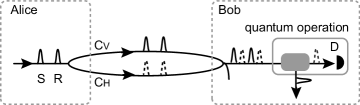
Suppose that Alice is given a signal photon in unknown state , where and represent horizontal (H) and vertical (V) polarization states, respectively, and . Alice uses another photon as a reference, which she prepares in a fixed state . She sends the signal photon in a time-bin following that of the reference photon with a temporal delay . The two-photon state can be written as
| (1) |
where the subscripts represent the temporal delay from the front time-bin. As shown in Fig. 1, the photons in the H- and the V-polarization state are transmitted through the channels CH and CV, respectively. While ordinary single-mode fibers can be used for these quantum channels at the cost of decreasing the success probability[22], here we use polarization-maintaining optical fibers (PMF) for the simplicity of the experiments. In this case, the polarization rotations of the photons in each channel do not occur, but unknown phase shifts and are added to the photons in each channel independently due to the fluctuations of the optical path lengths. We assume the interval between the signal and reference photons is much shorter than the correlation time of the fluctuations, so that the phase shifts are considered to be correlated such as and . At Bob’s location, the photons in both modes, CH and CV, are mixed together, and the received state becomes
| (2) |
Here the optical path lengths of CV and CH may differ, which is indicated by the temporal delay in the subscripts of the V-polarization states. We can easily see that the state is invariant under the phase shifts. It is worth mentioning that in the previous DFS schemes [12, 13, 14, 15, 16, 17], Alice prepares entangled states in the DFS. In our scheme, Alice’s two photons [Eq. (1)] are not correlated, let alone entangled. It is Bob who sifts out the entangled states in the DFS. Bob can, in principle, project the state (2) onto the state , which happens with the probability of , and decode the projected state into the faithful signal . In our experiment, this extraction of the faithful signal state from the received state is performed by passive linear optical elements and postselection using the photon detectors.
3 Experiment
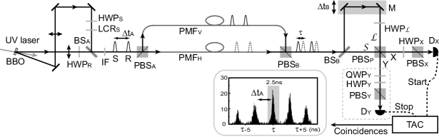
The schematics of the experimental set-up is shown in Fig. 2. Two photons in distinct modes are generated by SPDC from Type I phase matched 2-mm-thick -barium borate (BBO) crystals. One photon in passes through long path, and is transformed into arbitrary signal polarization states by rotating the polarization by a half wave plate HWPS and adding a phase shift by a liquid crystal retarder LCRS. The other photon in passes through short path, and is transformed into the fixed reference polarization state by HWPR. These photons are mixed by a non-polarizing beamsplitter BSA. Here we can prepare the two photons in the state (1) with the probability 1/4 when two photons are generated from SPDC. The temporal delay between the signal and the reference photon is about . The photons are split into the H- and V-polarization modes by a polarizing beam splitter PBSA which transmits the H-polarization photons and reflects the V-polarization photons. These photons are then transmitted to Bob through 10-m PMFH and PMFV.
At Bob’s location, these photons are mixed by PBSB again. If the optical path lengths of PMFH and PMFV were precisely adjusted with high stability, the received state would be the same as the state prepared by Alice. However, we did not perform any such stabilizations in the following experiments taking several hours of data accumulation, during which the phase shifts and fluctuated randomly.
The extraction of the signal state from the received two-photon state can be passively performed in the following way. The received two photons are first split into long path () and short path () by BSB, then mixed by PBSP again. HWPL rotates the polarization of the photons in the long path by 90∘. Using HWPX, PBSX, and a photon detector DX, the polarization of the photon in mode X is projected onto the diagonal state . The difference between the lengths of and corresponds to a temporal delay which is adjusted by the mirrors (M) on a motorized stage. The successful events are postselected by discriminating the time delay between the arrival of photons at detectors DX and DY by using the time resolving coincidence detection as shown in Fig 2. HWPY and the quarter wave plate QWPY in front of DY are used for the analyses of the successfully extracted signal states.
Here we only consider the successful case where the signal photon passes through and the reference photon passes through . This happens with the probability 1/4 when two photons arrived at the BSB. In this case the state just before the PBSP can be written as
| (3) |
where the superscripts represent the spatial modes. Here and include the phase shifts added in Bob’s interferometer. If one photon is emitted in each mode of X and Y, the output state just after the PBSP is . This operation is referred to as quantum parity checking [23], which is also useful for other quantum information tasks [24, 25]. Let us consider the case where . When the detector DX finds one photon, the state in mode X is projected onto . At that time, the state in mode Y is projected onto the state , implying that we faithfully obtain the signal state in mode Y. It is worth to mention here that the delay affects only the arrival time but not the fidelity of the output states as long as the correlation time of the fluctuations of the phase shifts added in Bob’s interferometer is much longer than .
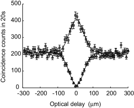
We first show that the above scheme can extract a faithful signal state in mode Y by properly adjusting the optical delay , when the signal state is . As shown in Fig. 3, varying the optical delay by moving M, we can clearly see the interference effects. The upper and lower curves show the coincidence rates on the bases and , respectively. The observed visibility at the zero delay is representing a clear signature that coherence is preserved during quantum state transmission. The small deviation from 100% visibility is due to the residual mode mismatch as well as multi-photon-pair generation during the SPDC. The full-width at half-maximum (FWHM) of the interference fringe, which corresponds to the coherence length of the photons, is found to be . This is roughly 100 times larger than the wavelength of the photons implying the robustness of the scheme against path-length mismatches and fluctuations up to the order of many wavelengths. The requirement for the precision of alignment and stability will be further relaxed if we choose the photons with longer .
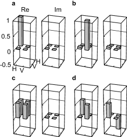
In order to characterize the performance of our transmission scheme precisely, we analyzed the output states via tomographic reconstruction of the density matrices for various signal states. Real and imaginary components of the density matrices of the output states are reconstructed for the input signal states, , , , and , and the results are shown in Fig. 4. The fidelities of these reconstructed density matrices to those of the initial signal states are calculated as, , , , and , respectively, which clearly shows that the output states are very close to the input signal states.
Since the above experimental results are enough to characterize completely the quantum operation effectively applied in our system, we can calculate various quantities for the demonstrated operation . In order to characterize quantitatively how close the operation is to the noiseless quantum channel, we calculate the average fidelity [26] which is defined as the average of the fidelites over all input states . It has been shown that is connected to entanglement fidelity by the following simple formula for qubit channels [27, 28], where represent a Bell state. The acts on one member of the Bell state and acts on the other. Instead of measuring by preparing the Bell state , we can estimate from the above reconstructed density matrices as and is calculated to be . This clearly shows that our qubit transmission scheme provides a high fidelity to noiseless quantum channel.
The proof-of-principle experiment demonstrated here uses passive linear optical elements, thus the probability of success is rather small than the ideal case. However the success probability will increase 16 times by replacing the BSA and BSB by fast optical switches, and twice by using feed-forward decoding techniques. Excluding the fiber losses and the detection loss, these improvements will enable a success probability of 1/2. In the present experiment, we used PMFs as a channel, but our scheme also allows the use of standard single-mode fibers[22]. It is worth noting that the photon losses in optical fibers may affect the efficiency in this two-photon quantum communication scheme more than in the single photon transmission, but the efficiency will be greatly improved by the use of quantum repeaters[5].
4 Conclusion
This work demonstrates that two-photon interference effect together with quantum parity checking can be used for faithful transmission of qubits in arbitrary unknown quantum states with the help of ancillas without active control and stabilization mechanisms. Simplicity, versartaility, and maintenance-free feature of the scheme will be important for future quantum communication networks.
5 Acknowledgements
This work was supported by 21st Century COE Program by the Japan Society for the Promotion of Science and a MEXT Grant-in-Aid for Young Scientists (B) 17740265.
References
- [1] C. H. Bennett, and G. Brassard, in Proceedings of IEEE International Conference on Computers, Systems, and Signal Processing, IEEE, 175 (1984).
- [2] A. K. Ekert, Phys. Rev. Lett. 67, 661 (1991).
- [3] N. Gisin, G. Ribordy, W. Tittel, and H. Zbinden, Rev. Mod. Phys. 74, 145 (2002).
- [4] C. H. Bennett, et al. Phys. Rev. Lett. 70, 1895 (1993).
- [5] H. -J. Briegel, W. Dür, J. I. Cirac, and P. Zoller, Phys. Rev. Lett. 81, 5932 (1998).
- [6] R. Raussendorf, and H. J. Briegel, Phys. Rev. Lett. 86, 5188 (2001).
- [7] C. H. Bennett and S. J. Wiesner, Phys. Rev. Lett. 69, 2881 (1992).
- [8] A. Karlsson, and M. Bourennane, Phys. Rev. A 58, 4394 (1998).
- [9] M. Hillery, V. Buzek, and A. Berthiaume, Phys. Rev. A 59, 1829 (1999).
- [10] A. Muller, et al. Appl. Phys. Lett. 70, 793 (1997).
- [11] D. Stucki, et al., New J. Phys. 4, 41 (2002).
- [12] P. G. Kwiat, A. J. Berglund, J. B. Altepeter, and A. G. White, Science 290, 498 (2000).
- [13] Z. D. Walton, et al., Phys. Rev. Lett. 91, 087901 (2003).
- [14] J. -C. Boileau, R. Laflamme, M. Laforest, and C. R. Myers, Phys. Rev. Lett. 93, 220501 (2004).
- [15] Y. Jiang, X. Wang, , B. Shi, & A. Tomita, Opt. Express 13, 9415 (2005).
- [16] Q. Zhang, et al. Phys. Rev. A 73, 020301(R) (2006).
- [17] T. -Y. Chen, et al. Phys. Rev. Lett. 96, 150504 (2006).
- [18] C. H. Bennett, Phys. Rev. Lett. 68, 3121 (1992).
- [19] C. Gobby, Z. L. Yuan, A. J. Shields, Appl. Phys. Lett. 84, 3762 (2004).
- [20] T. Kimura, et al. Jpn. J. of Appl. Phys. 43, 1217 (2004).
- [21] S. D. Bartlett, T. Rudolph, and R. W. Spekkens, Phys. Rev. Lett. 91, 027901 (2003)
- [22] T. Yamamoto, et al., Phys. Rev. Lett. 95, 040503 (2005).
- [23] T. B. Pittman, B. C. Jacobs, and J. D. Franson, Phys. Rev. A 64, 062311 (2001).
- [24] T. Yamamoto, M. Koashi, Ş. K. Özdemir, and N. Imoto, Nature 421, 343 (2003).
- [25] J.-W. Pan, et al., Nature 423, 417 (2003).
- [26] B. Schumacher, Phys. Rev. A 54, 2614 (1996).
- [27] M. Horodecki, P. Horodecki, and R. Horodecki, Phys. Rev. A 60, 1888 (1999).
- [28] M. A. Nielsen, Phys. Lett. A 303, 249 (2002).