Reaching 7Li BEC with a Mini-Trap
Abstract
A novel mm-scale Ioffe-Pritchard trap is used to achieve Bose-Einstein condensation in 7Li. The trap employs free-standing copper coils integrated onto a direct-bond copper surface electrode structure. The trap achieves a radial magnetic gradient of 420 G/cm, an axial oscillation frequency of 50 Hz and a trap depth of 66 G with a 100 A drive current and 7 W total power dissipation.
pacs:
39.90.+d, 39.20.+q, 39.10.+jI Introduction
Forced evaporative cooling in conservative magnetic traps has become a key technology to cool atoms to quantum degeneracy. In 1995, the invention of the time-orbiting potential (TOP) trap paved the way to the first Bose-Einstein condensate (BEC) Rb-BEC . In the following years, the cloverleaf trap clover , the QUIC trap quic , and other conservative traps allowed further improvements in trap performance. More recently, magnetic traps have been realized with micro-fabricated wires on a surface (atom chips) atomchip1 ; atomchip2 .
In this paper we report on the realization of a novel Ioffe-Pritchard Pethick trap which is a hybrid between free-space and surface geometries. This trap is both deep and tightly confining while consuming relatively little power. The trap has allowed for successful evaporation of a sample 7Li in the ground state to quantum degeneracy. As evaporative cooling of 7Li is challenging due to its relatively small scattering length LiBEC_hulet ; French_lithium , we expect this trap to scale well to evaporation of heavier alkalies such as Na and Rb.
The paper is organized as follows. We start by reviewing top level design criteria for magnetic traps. We then describe our implementation. Finally we present data on efficient evaporation to BEC.
II Magnetic trap design criteria
The performance of a magnetic trap depends on both local and global parameters. The local parameters are the parameters near the center of the trap, such as the gradient and curvature of the potential energy. The global parameters are the parameters of the boundary of the trap, such as the trap depth and the trap volume. Both global and local parameters are important for achieving efficient evaporation and for obtaining large numbers of degenerate atoms at the end of evaporative cooling. These parameters are affected by the size and geometry of the trap.
Let us first look at the local parameters. In a typical Ioffe-Pritchard trap, the radial magnetic field gradient and the axial magnetic field curvature scale as and respectively, where is the current flowing in the magnet wires and is the distance from the wires to the center of the trap. If we assume the current density in the wires is and that trap dimensions scale linearly with , then the current of the trap will scale as , so the radial magnetic field gradient scales as and the axial magnetic field curvature scales as . In theory, a small trap only gains in the axial magnetic field curvature. In reality, it is hard for a large trap to maintain the same current density as a small trap since the power dissipation scales as while the temperature drop with respect to the heat sink increases as . As a consequence, increasing the size of the trap requires either a compromise in the current density or the overhead of water cooling. In addition, as solid conductors would imply currents so large as to be unpractical for power supplies and current leads, large magnetic traps are realized with multiple windings, with wire isolation further reducing the effective current density. In micro-traps the current density in the wires can be orders of magnitude larger than in traditional magnetic traps due the close proximity of the conductor to the heat sink. In the end, in order to optimize local parameters, a small trap is preferred over a large trap.
Now let us look at the global trap parameters. The trap depth of an Ioffe-Pritchard trap, which is determined by one of the 6 saddle points (4 in the radial direction and 2 in the axial direction), scale as . The trapping volume scales as . It is important that the trap depth is higher than the average initial kinetic energy of the atomic ensemble in order to ensure that a substantial fraction of atoms is initially confined in the trap. Furthermore, the trapping volume should be comparable to the size of the initial ensemble, or again a significant fraction of the atoms will fail to be initially confined. Small traps rely on auxiliary coils to adiabatically compress the atom distribution. The effectiveness of this compression is limited by two factors. First, compression increases the ensemble temperature, thus raising the required trap depth of the small trap. Second, for a quadruple-type potential, the most widely used for this purpose, shrinking the size of the sample by a factor is achieved at the cost of an higher current and an larger dissipated power. As a consequence, while small traps feature better local parameters, large traps are superior in terms of global parameters.
Trap parameters are also affected by the geometric arrangement of the magnet wires. For example, the “Z” trap atomchip2 has a planar structure and is well suited for atom chip designs, but it is not as effective as a standard Ioffe-Pritchard trap in terms of optimizing local and global parameters: in the radial direction, with the same trap depth and trap volume, the “Z” trap has a factor of 4 weaker radial field gradient; in the axial direction, the trap depth is a factor of lower with the same trapping volume.
III The mini-trap
Based on the above considerations, we designed a trap for evaporative cooling of 7Li seeking the best compromise between the local and global parameters. A similar approach has been followed by other groups recently for Rb Schmiedmayer ; Dan . However, Li puts tighter constraints on the design for three reasons. First, Li does not support sub-Doppler laser cooling. As a consequence Li atoms are almost an order of magnitude hotter than Rb before loading the magnetic trap. Second, the s-wave elastic collision cross-section of Li is an order of magnitude smaller LiScatter than that of Rb RbScatter . This, combined with a high two-body loss rate, impedes the evaporative cooling process. Finally, since the elastic collision cross-section drops with increased temperature daliba , the use of adiabatic compression to increase the elastic collision rate is ineffective. When designing our mini-trap, typical Li MOT parameters were used to set trap global parameters. We then attempted to maintain a tight electrode structure to maximize the local parameters. The resulting trap design is discussed below.
III.1 Mini-trap construction
A schematic view of the mini-trap assembly is shown in Fig. 1. The trap is comprised of four parts: the free-standing electrode structure, the DBC chip, the negative current lead and the positive current lead.
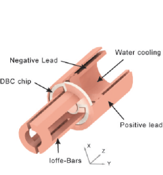
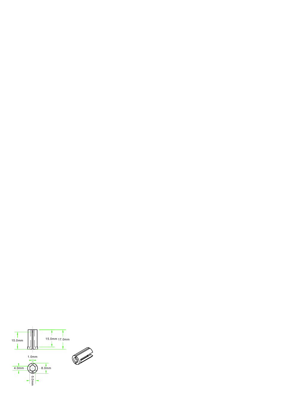
The first part, shown in Fig 2, is machined from a solid piece of oxygen-free copper. We start from a 17 mm long tube, with 5 mm inner diameter and 8 mm outer diameter. Two slits, respectively 4 mm and 1 mm wide, are cut orthogonally through the tube in the longitudinal direction, stopping 2 mm from opposite ends. In this manner, the partial rings at the ends of the tube form pinch coils, while the remaining length is divided into 4 Ioffe bars. One end of the tube is brazed to a DBC ceramic chip.
The second part is the DBC chip. In the DBC process, Cu foil is typically bonded to an alumina ceramic substrate in an N2 gas atmosphere at C. Reaction compounds such as CuAlO2 and CuAl2O4 form a strong bond in the vicinity of interface between Cu and the alumina substrate. Traces are then etched from the copper foil. In our case, we designed traces to route current through the Ioffe bars to the current leads. Compared to other mature micro-fabrication approaches such as thin film processes and thick film processes, DBC provides better thermal conductivity and allows for significantly larger currents on the copper layer.
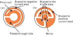
The schematics for the DBC chip are shown in Fig. 3. The small via on the pad provides an electrical conduit between both sides of the chip. On the front side of the chip, the outer trace is welded to the positive lead of the power supply. In addition, a Cu disc in the center is polished to form a mirror that can be used to retro-reflect a laser beam (to achieve an optical lattice, for example). On the back side of the chip, the inner ring has the same diameter as the copper piece and works as the other pinch coil for the Ioffe-Pritchard trap. The outer ring is welded to the negative lead of the power supply and the heat sink.
The third piece of the assembly is the negative current lead. The middle of the lead is hollow and blind to run water cooling. The fourth piece of the assembly is the positive current lead. It is concentric with the negative current lead to avoid disturbing the trap field.
The Ioffe bars and the current leads are welded to the DBC chip in a high temperature (C) vacuum furnace. The material and brazing process are all ultra-high vacuum compatible.

III.2 Predicted performance
Calculations of the predicted magnetic field in the radial and axial directions are shown in Fig. 4. All fields are calculated for a 100 A trap current. The asymmetry in the radial direction is due to the asymmetry of the Ioffe bars. Because we seek a large numeric aperture in the x-direction for imaging, the distance between the Ioffe bars in the x-direction is larger than that in the y-direction. In the axial direction, the pinch coil at the tip of the trap is only a partial circle, while on the back of the chip, there is a full circle of copper trace. As a result, the field is weaker at the tip of the trap than close to the chip. Away from the center, the field gradient in the radial direction is about 800 G/cm in the x-direction and 400 G/cm in the y-direction. In the area near the center of the trap, so that = 510 G/cm. In the axial direction, the oscillation frequency is predicted to be 67 Hz. The trap depth of 70 G is due to the saddle point in the y-direction.
III.3 Evaporative cooling apparatus
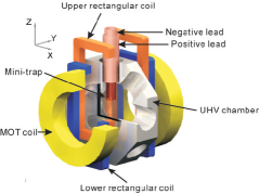
The mini-trap is integrated into an evaporative cooling apparatus which is illustrated in Fig. 5. In brief, a transversely cooled atomic beam loads a 3D MOT. Atoms from the 3D MOT are then optically pumped and transferred into the mini-trap, located 2 cm above the MOT. Auxiliary rectangular magnetic coils are used to move the atoms from the MOT region to the mini-trap region. We detail each of these steps below.
The trap is loaded from a transversely laser cooled Li atomic beam. Laser cooling is achieved by two pairs of zigzag broadband laser beams Fabio . The 2D cooling region is separated from the main vacuum chamber (which contains the mini-trap) by a differential pumping tube. Atoms entering the main chamber are slowed and captured by a broadband 3D MOT brian . atoms are loaded into the MOT in 30 s. The loading rate is primarily determined by the Li oven temperature, which is kept suitably low to maintain the high vacuum conditions required for evaporative cooling.
After loading atoms into the 3D MOT, atoms are optically pumped by a combination of hyperfine pumping and Zeeman pumping to the state. Zeeman pumping is accomplished with a circularly polarized laser which is tuned to F=2 F’=2 transition. Unlike the line, the line has a well resolved fine structure and the ground state is a dark state under excitation from circularly polarized pumping light. A bias field is pulsed on during the Zeeman pumping interval.
Following the optical pumping sequence, atoms are held in a magnetic quadrupole trap formed from the same coils used for the MOT. Atoms are then transferred from the quadruple trap by ramping down the current in the MOT coils and ramping up the current in the lower rectangular coils in 50 ms. In this step, the center of the atom cloud does not change but the shape of the cloud becomes elongated. Next we ramp down the current in the lower rectangular coils and ramp up the current in the upper rectangular coils in 70 ms. After this step, the elongated atom cloud is in the center of the mini-trap, 2 cm above the center of the MOT.
It is important to transfer the atoms from the quadruple trap to the mini-trap with a minimum loss of phase space density. In order to minimize heating during the final transfer step, we implemented a semi-adiabatic transfer scheme. The idea is as follows. The radial confinement of the mini-trap is more than 2 orders of magnitude stronger than the axial confinement. We switch off the rectangular transfer coils and switch on the mini-trap in a time scale that is much slower than the radial oscillation period but much faster than the axial oscillation period. In this case, we achieve adiabatic transfer in the radial direction, and therefore only need to match the trap geometry in the axial direction (which can be accomplished by appropriate design of the rectangular transfer coils). We implemented the semi-adiabatic transfer by ramping down the current in the upper rectangular coils and ramping up the current in the mini-trap in 2 ms. Using this method, we achieved a transfer efficiency of 25% from the rectangular coils into the mini-trap. 100 msec after the transfer, roughly atoms remain in the mini-trap.
Due to the minimum loss of phase space density during the transfer process, we achieved efficient evaporative cooling without an additional Doppler cooling stage in the Ioffe-Pritchard trap French_lithium . To test the effectiveness of the semi-adiabatic transfer, we reversed the current flow in the rectangular transfer coils. Although the atoms experience the same potential before and after the transfer, the transfer is no longer semi-adiabatic, and nearly all atoms are lost from the mini-trap in just 2 s.
IV Trap characterization
We characterized the trap through RF and Zeeman spectroscopy and parametric heating measurements, as described below.
The magnetic field in the center of the trap was measured using RF spectroscopy. For these measurements – and also for evaporative cooling – we employed a swept RF source to eject atoms from the trap at energies determined by the RF frequency. Atoms were ejected using transitions to the untrapped state. When the applied RF frequency reaches
| (1) |
all atoms are ejected from the trap. Here = 803.5 MHz is the groundstate hyperfine interval, is the magnetic field at the trap bottom, and is the Landé g-factor (primes distinguish between the initial and final state).
For our measurements, we first prepared a 6 K sample by sweeping the RF frequency from 980 MHz down to 805 MHz. We then applied a constant RF frequency cut for 10 s. Fig. 6(a) shows the number of atoms remaining in the trap as a function of this frequency. The sudden jump in atom number was used to measure the magnetic field at the bottom of the trap. Our trap bottom measurement has a frequency resolution of better than 10 kHz.

At 100 A, the bottom of the trap was measured to be 7 G, significantly lower than the calculated value of 17 G. We confirmed this through direct measurement of the magnetic field of a to-scale model of the trap. We believe this discrepancy can be explained by consideration of non-uniformities in the current distribution in the leads on the DBC chip. Finally, we verified that the magnetic field at the trap bottom scaled linearly with the trap current.
Because the minimum field resulting from the mini-trap alone is relatively low, it can be precisely manipulated with an external bias coil. Tuning of the field minimum in this way can be used to control the radial curvature of the trap. For the evaporative cooling demonstration described below, we have added an extra field so that the overall trap minimum is 0.4 G.
We used Zeeman spectroscopy to measure the depth of the trap. For these measurements, we confined atoms in a relatively weak 36 A trap, in the state, in order to ensure full filling of the trap. We then applied a 4 sec, single frequency, excitation to drive Zeeman transitions to the untrapped state. We subsequently measured the number of atoms remaining in the trap, as shown in Fig. 6(b). From this data we inferred a trap depth of 66 G when results were scaled to 100 A operating currents. This value is in good agreement with our simulated values.
The local parameters of the mini-trap were measured by parametric heating. We parametrically heated atoms with an additional audio frequency current (3 A) which was summed with the DC trap current. To make the measurement we first prepared a 6 K ensemble with an RF sweep to 805 MHz. After preparing this ensemble we turned on the parametric excitation for a 10 sec interval. Following the excitation interval we measured, using absorption imaging, the optical depth at the trap center. When the modulation frequency and the atom oscillation frequencies (radial frequency), (axial frequency) satisfy the resonance conditions or (n integer), the parametric process heats the atom ensemble and causes a reduction in the peak optical density. The and resonances for a 100 A DC trap current and center bias field of 0.4 G are shown in Fig. 7.

From Fig. 7, we find a trap axial oscillation frequency of 50 Hz and radial oscillation frequency of 3 kHz. From
| (2) |
we calculate that the axial curvature is 120 G/cm2 (mLi is the Li atomic mass). Similarly, in the radial direction, we obtain G/cm2. From
| (3) |
and G, we find the radial magnetic field gradient G/cm. These results are in reasonable agreement with the predicted fields.
V Evaporative cooling to BEC
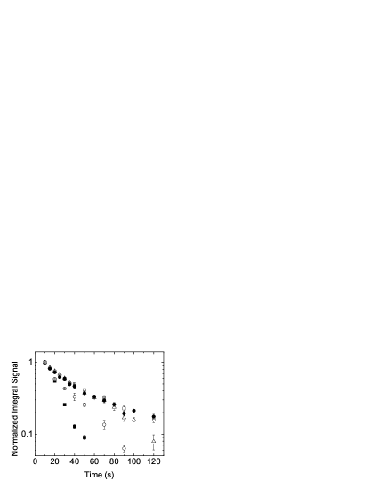
In order to optimize parameters for evaporative cooling, we measured the trap lifetime as a function of trap current, as shown in Fig. 8. Our trap achieved a lifetime of 87 s at 78 A, limited by the vacuum in the main chamber. The lifetime decreased with higher mini-trap currents, presumably due to degradation of the vacuum due to resistive heating of the trap electrodes. However, at 120 A we still achieved a trap lifetime of 60 sec, which was sufficient to support effective evaporative cooling. At this current, the current density was 35 A/mm2 in the Ioffe bars and as high as 200 A/mm2 in the pinch coil on the DBC chip.
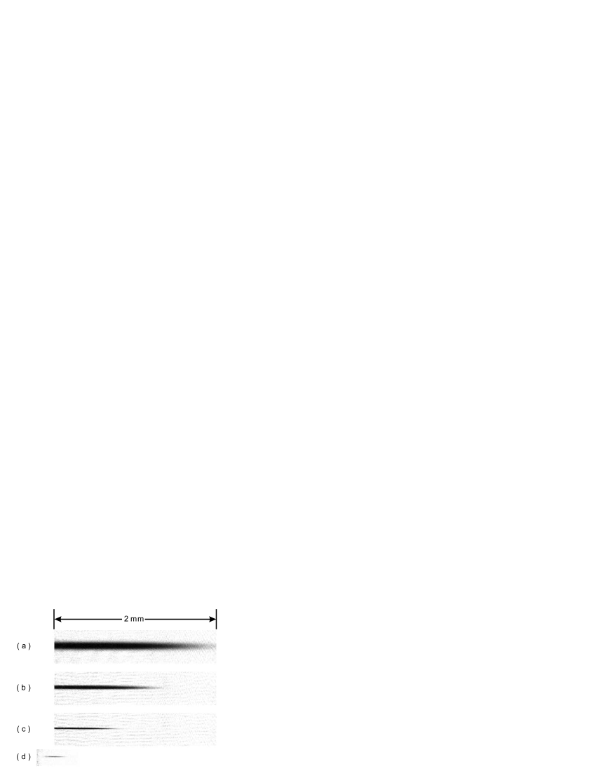
To evaporatively cool trapped atoms we applied a 35 sec RF sweep from an initial RF frequency of 980 MHz to a final RF frequency close to . The sweep consisted of piecewise linear steps which were independently optimized in order to maximize phase space density at the end of the RF sweep. We inferred phase space density from absorptive imaging measurements of atom number and temperature, and the measured trap frequencies. Our imaging system had a diffraction limited resolution of 4 m. Typical absorption images of evaporatively cooled ensembles are shown in Fig. 9.
We extracted number and temperature from these images using the following procedure. First, the axial profile of the cloud is fitted to a Gaussian distribution and the size is used to deduce the temperature from
| (4) |
where is the measured axial oscillation frequency. The peak density is deduced from the central optical density together with the radial size of the cloud . The central phase space density is , where is the thermal de Broglie wavelength.

In Fig. 10(a), we plot the phase space density as a function of atom number in the trap following the evaporative cooling sweep. The evaporation efficiency (where and are the initial and final numbers of atoms) is observed to be 2 for phase space densities from to , comparable to previous Li BEC experiments LiBEC_hulet ; French_lithium . When the phase space density approaches the quantum degenerate region, we observe a reduction in evaporation efficiency to 1. Here it is limited by two-body dipolar relaxation losses Dipolar ; Optimization . A plot of phase space density vs. temperature is shown in Fig. 10(b).
Below the BEC transition, the negative scattering length limits the number of condensed atoms to 600 atoms BEClimitTheory ; BEClimitExperiment . When the BEC fraction exceeds this number, the BEC collapses and these atoms are ejected from the trap. In this work, we did not attempt to resolve the BEC fraction near the phase transition. However, we were able to image very small ensembles of atoms ( 300 atoms) in a nearly pure condensate state. We reach the BEC threshold with roughly atoms.
VI Conclusion
In conclusion, we have used a mm-scale mini-trap to achieve BEC in 7Li. We demonstrated a semi-adiabatic method to load the trap. We characterized trap parameters using RF and Zeeman spectroscopy and parametric heating measurements. The trap dissipates only 7 W power for operating parameters needed to achieve BEC.
It is interesting to consider extensions of this work to heavier bosons such as Na or Rb, or for sympathetically cooled mixtures of these species and other species (e.g. fermions). In these cases, the efficacy of sub-Doppler laser cooling methods should enable further miniaturization of the trap electrode structure. As a result, power consumption could be an order of magnitude lower ( 1 W). In addition, evaporation times are expected to be much faster than those obtained above, due to the significantly larger elastic collision cross-sections of Rb or Na. The performance of such a trap could compete favorably with other fast-evaporation systems, such as micro-traps ChipBEC1 and all-optical traps all_optical . Ultimately, we expect this class of traps could have broad impact for portable BEC systems.
Acknowledgements.
This work was supported by DARPA and the NSF. We thank Wayne Rowlands, Fabio Peixoto, and Gilles Nogues for their assistance in early stages of this work.References
- (1) M. H. Anderson, et. al., Science 269, 198 (1995).
- (2) M. Mewes, et. al., Phys. Rev. Lett. 77, 416 (1996).
- (3) T. Esslinger, I. Bloch, and T. Hänsch, Phys. Rev. A 58, 2664 (1998).
- (4) J. Fortagh, A. Grossmann, C. Zimmermann, T. W. Hänsch, Phys. Rev. Lett. 81, 5310 (1998).
- (5) J. Reichel, W. Hänsel, T. W. Hänsch, Phys. Rev. Lett. 83, 3398 (1999).
- (6) C.J. Pethick and H. Smith, Bose-Einstein Condensation in Dilute Gases (Cambridge University Press, New York, 2002).
- (7) C. C. Bradley, C. A. Sackett, J. J. Tollett, and R. G. Hulet, Phys. Rev. Lett. 75, 1687 (1995)
- (8) F. Schreck, et. al., Phys. Rev. A 64, 011402(R) (2001).
- (9) K. L. Moore et. al., Appl. Phys. B 82, 533 (2006).
- (10) A. Kasper, et. al., J. Opt. B: Quantum Semiclass. Opt. 5, S143 (2003).
- (11) E. Abraham, C. Sackett, and R. Hulet, Phys. Rev. A 55, 3299 (1997).
- (12) H. M. J. M. Boesten, et. al., Phys. Rev. A 55, 636 (1997).
- (13) J. Dalibard. in Bose-Einstein Condensation in Atomic Gases, Proceedings of the International School of Physics Enrico Fermi, edited by M. Inguscio, S. Stringari, and C. Wieman (AIOS Press, Amsterdam, 1999).
- (14) F. Peixoto, Yale University PhD Thesis, 2002.
- (15) B. Anderson and M. Kasevich, Phys. Rev. A 50, 3581 (1994).
- (16) C. A. Sackett, C. C. Bradley, and R. G. Hulet, Phys. Rev. A 55, 3797, (1997).
- (17) A.J. Moerdijk and B.J. Verhaar, Phys. Rev. A 53, R19 (1996).
- (18) P.A. Ruprecht, et. al., Phys. Rev. A 51, 4704 (1995).
- (19) C. C. Bradley, C. A. Sackett and R. G. Hulet, Phys. Rev. Lett. 78, 985 (1997).
- (20) W. Hänsel, P. Hommelhoff, T. W. Hänsch and J. Reichel, Nature 413, 498 (2001).
- (21) M. D. Barrett, J. A. Sauer, and M. S. Chapman, Phys. Rev. Lett. 87, 010404 (2001); T. Kinoshita, and D. S. Weiss, Phys. Rev. A 71, 011602(R) (2005).