Dispersion spreading of biphotons in optical fibres and two-photon interference
Abstract
We present the first observation of two-photon polarization interference structure in the second-order Glauber’s correlation function of two-photon light generated via type-II spontaneous parametric down-conversion. In order to obtain this result, two-photon light is transmitted through an optical fibre and the coincidence distribution is analyzed by means of the START-STOP method. Beyond the experimental demonstration of an interesting effect in quantum optics, these results also have considerable relevance for quantum communications.
pacs:
42-50-p, 03.67.Hk, 42.62.EhIn many quantum communication, quantum computation and quantum metrology Gisin experiments, entangled states of light are transmitted through optical fibres. For example, quantum key distribution through fibres has already been demonstrated up to 100 km Mo . Because of these applications, a clear understanding of the effect of fibre propagation on the properties of entangled states is highly demanded. This understanding would be also very useful for the studies on the foundations of quantum mechanics Genovese .
In particular, it is known that an entangled two-photon state, a biphoton, spreads in time when propagating through a medium with group velocity dispersion. More specifically, the second-order intensity correlation function of two-photon light gets broadened and at a sufficiently large distance, it takes the shape of the spectrum Chekhova , Valencia . It turns out that for biphotons propagating through a dispersive medium, the shape of the correlation function can manifest the effects of two-photon interference.
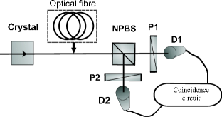
In a typical experiment on observing two-photon interference for type-II spontaneous parametric down-conversion (SPDC) (Fig.1), pairs of orthogonally polarized signal and idler photons generated in the collinear frequency-degenerate regime are sent to a non-polarizing beamsplitter (NPBS) followed, in both arms, by polarizers (P1, P2) and photon counting detectors (D1, D2). When one of the polarizers is rotated, the counting rate of the corresponding detector does not vary, but the coincidence counting rate varies with almost 100% visibility (polarisation fringes) Shih . Another way to observe two-photon interference is to vary the phase between signal and idler photons (space-time fringes) Shih1 . Such an experiment can also be interpreted as preparation of entangled two-photon Bell states in the two spatial modes after the beamsplitter Pittman .
In addition to space-time and polarization fringes, two-photon interference can manifest itself in the modulation of the coincidence counting rate due to the displacement of one or both detectors in the near-field or far-field zone Burlakov or variation of the frequency registered by one or both detectors Viciani . However, to the best of our knowledge, there have been no experiments on observing two-photon interference in the shape of the second-order intensity correlation function for SPDC, although a related experiment has been recently performed for a narrow-band two-photon source based on an OPO operating below threshold Ou . The main reason is that normally, the width of the correlation function for SPDC radiation is on the order of hundreds of femtoseconds, and it cannot be resolved using the existing equipment. However, after a fibre of length about several hundred meters, the width of the correlation function grows to several nanoseconds, which enables the interference to be observed.
In a setup shown in Fig.1, the state vector of the biphoton field at the output of the beamsplitter is
| (1) |
where is the spectral two-photon amplitude, is the frequency shift, are photon creation operators in the horizontal and vertical polarization modes (denoted by ) and two spatial modes (denoted by ); , being the pump frequency, and the terms corresponding to the case where both photons of the two-photon state go to the same port of the beamsplitter have been omitted. The difference between the group velocities of signal and idler photons in the non-linear crystal where SPDC occurs leads to the factors by the two terms of Eq. (1), where , with being the crystal length and the inverse group velocity difference. To observe two-photon interference in type-II SPDC, this delay has to be compensated by means of a birefringent crystal. However, as one will see from what follows, compensation is not necessary in the presence of the fibre.
The coincidence counting rate can be calculated as
| (2) |
where is the second-order Glauber’s correlation function defined as
| (3) |
are positive- and negative-frequency field operators at the photodetectors, integration in is performed over the measurement time interval, and integration in , over the coincidence circuit resolution window Mandel . If SPDC is obtained from a cw pump (the stationary case), does not depend on .
One can show Shih that two-photon interference manifests itself most explicitly in the difference between coincidence counting rates for two cases. In the first case, both polarizers are oriented at 45 degrees to the horizontal direction. In the second case, polarizer 1 is oriented at and polarizer 2, at to the same direction.
For these two configurations of the polarizers ( and ), the correlation function takes the forms
| (4) |
where is the Fourier transform of the spectral amplitude .
Note that for type-II SPDC the amplitude has a rectangular shape with width Rubin . Hence, if the delay is not compensated, the two amplitudes in Eq. (3) do not overlap and the interference is absent: the coincidence counting rate, given by the integral of Eq. (4) over , is the same for and positions of the polarizers.
If the biphoton beam, before entering the beamsplitter, passes through a sufficiently long fibre (with length ) sufflength , the biphoton amplitude becomes Chekhova
| (5) |
where are, respectively, the first and the second derivatives of the fibre dispersion law at the frequency . Here, we assume that the group velocity dispersion is the same for both polarizations.
Since for type-II SPDC Shih - Pittman ,
| (6) |
where is the shifted time and is the typical width of the correlation function after the fibre Krivitsky .
Taking into account that , one can rewrite Eq. (6) as
| (7) |
Thus, in the presence of the fibre, two-photon interference can manifest itself in the shape of the second-order Glauber’s correlation function. However, if the correlation function is integrated over all delays (which is the case in most experiments on two-photon coincidence counting), the result will be the same for both configurations of the polarizers. To see the structure given by Eq.s (7), one has to measure the correlation function with a sufficiently good time resolution. Two main reasons for the resolution reduction must be considered: the time jitter of the detectors (typically of the order of several hundreds of picoseconds), which sets the ultimate time resolution of the measurements, and the jitter contribution of the electronics (amplitude walk and noise) used for the coincidence detection.
Coincidence detection by means of a coincidence logic gate circuit typically shows resolving time, for commercial available devices, of a few nanoseconds, which can be much greater than the spread of the correlation function because of the propagation in a dispersive fibre.
Another widely used coincidence detection technique, which will be further called the START-STOP method, involves direct measurement of the time delay between the photocount pulses of the two detectors by means of a time-to-amplitude converter (TAC), which converts linearly the time interval between the two input pulses (START and STOP) into an output pulse of a proportional amplitude. This analog pulse is forwarded to a multichannel analyzer (MCA), which gives the histogram of the input pulse amplitudes corresponding to the probability distribution for the time interval between the counts of the two detectors. One can show Mandel that in the limit of small photon fluxes, this time interval distribution coincides in shape with the second-order intensity correlation function. The resolution of such technique could be on the order of one picosecond if the detector jitter time were negligible. The expected experimental coincidence distribution, in the case of negligible jitter time contribution from the experimental apparatus, was calculated numerically (Fig.2a) for the following parameters: , fibre length , , crystal length . The corresponding FWHM of the correlation function after the fibre is ns ().
One can see that for the polarizers set at (), destructive interference occurs at the center of the peak. On the other hand, for the polarizers set at (), there is constructive interference at the centre of the peak. High-visibility polarization interference can be observed in this case by selecting only several channels of the MCA corresponding to the center of the peak and rotating one of the polarizers.
If we take into account the time jitter of the experimental setup, the interference structure gets smeared. In Fig.2b we show the numerical evaluation of the coincidence distribution with an account for the time jitter of the experimental apparatus, which is the convolution of the peak plotted in Fig.2a with a 750 ps (a typical jitter for two commercial APD detectors) FWHM Gaussian function. One can see that in the case of Fig.2b, the change in the number of coincidences observed at zero delay for (,) and (, ) orientations of the polarisers corresponds to only 45% visibility, unlike in the case of Fig.2a, where almost 100% visibility is observed.
It is worth hinting to what happens if the e-o delay is compensated partly, by means of a birefringent material introducing an opposite-sign delay. Here forth we only mention that the period of the sine and cosine functions in Eqs. (7) increases above the width of the envelope and thus the integral numbers of coincidences corresponding to the two polarizer configurations differ. As a result, there is nonzero visibility even in the absence of the correlation function time selection. For complete compensation, the visibility would be %.
In order to experimentally observe two-photon interference in the shape of the correlation function of biphotons, we have generated biphoton pairs via SPDC by pumping a type-II 0.5 mm BBO crystal with a 0.1 Watt CW laser beam at the wavelength 351 nm in the collinear frequency-degenerate regime. No compensating birefringent material was used after the crystal. Then the pump beam was eliminated by a high-reflectivity UV mirror plus an anti-UV cutoff filter and the SPDC radiation was coupled to a 250 m - long single-mode fibre with FMD by a 20x microscope objective lens. In order to increase the efficiency of coupling SPDC radiation into the fibre, the pump was focused into the crystal using a lens with the focal length 13.5 cm. Because of the rapid polarization drift in the fibre, a fibre polarization controller was introduced at the output. After the fibre, the biphoton pairs were addressed to a nonpolarizing beamsplitter and two photodetection apparatuses (consisting of polarisers, red-glass filters and APDs). The photocount pulses of the two detectors, after passing through delay lines, were analyzed by means of the START-STOP method, and the second-order correlation function, , was observed at the MCA output. The FWHM of the coincidence peak in the absence of the fibre was measured to be 0.75 ns, a value substantially determined by the APD time jitter. The resolution determined by the MCA channel width, in our case 2.5 ps, is much smaller and therefore negligible.
If the biphotons propagate through the fibre, the FWHM grows up to ns. The peak observed without polarization selection is shown in Fig.3a. In the presence of the polarizers, the shape of the peak changes (Fig.3b,c). For the (;) settings of the polarizers, destructive interference in the middle of the peak leads to a shape in agreement with the calculated one (Fig.2b). For the polarizers set at (;), as expected, there is a maximum at the center of the peak. If only the central part of the peak is selected, the observed variation in the number of coincidences due to the change in the polarizer settings corresponds to 35% visibility of polarization interference.
In summary, we have observed effects of two-photon interference in the shape of the second-order Glauber’s correlation function for biphoton light generated via type-II SPDC and transmitted through an optical fibre. It is worth noticing that our results show how, for a sufficiently long fibre (hundreds of meters), a Bell state can be generated without compensating for the e-o delay between the signal and the idler photons. In this particular method of Bell states preparation, distinguishability of the interfering two-photon amplitudes is erased by spreading them in time and by selecting coincidences within a suitable time window. Even if this method could appear more complicated than the traditional one, based on using additional birefringent elements, it is interesting as a conceptually different way for restoring entanglement. In this sense it must be noticed that selection of the coincidence time window is similar to the frequency selection, which can be achieved by using narrow-band filters in some experiments on Bell-state preparation Gisin ; Shih2 , since the group-velocity dispersion of the fibre actually performs the Fourier transformation of the biphoton spectrum into the correlation function Chekhova . However, this does not mean that the observed interference is present in the spectrum of the down-converted photons, since the observed shape of the correlation function substantially depends on the polarizer settings in both arms, which, in the general case, are different. Another distinction forth from the experiments where narrow-band filters are used for the Bell states preparation consists of the fact that, in our experiment, one can achieve high visibility by selecting not necessarily the central part of the two-photon peak but any symmetric side parts where the coincidence counting rates differ for different polarizer settings (see Fig.2). Furthermore, one should notice that these effects inevitably occur in any quantum communication experiment where biphoton light is transmitted through optical fibres, and if the fibres are sufficiently long and temporal selection of the coincidences is provided, there is no need for o-e delay compensation.
Finally, we would like to mention that the measurement of the observed broadening of the second-order Glauber correlation function could eventually be used for the evaluation of the optical fibre chromatic dispersion (in analogy to Ref. Brendel ).
I Acknowledgments
This work was supported by MIUR (FIRB RBAU01L5AZ-002), by ”Regione Piemonte E14”, by Fondazione San Paolo, and by the Russian Foundation for Basic Research, grant No. 05-02-16391. One of us (L.K.) acknowledges the support of Intas Grant for young scientists No. 03-55-1971.
References
- (1) N. Gisin et al., Rev. Mod. Phys. 74 (02) 802; T.B. Pittman et al., quant-ph/0406192; G. Brida et al., quant-ph/0505227, Laser Phys. Lett. in press, DOI 10.1002/lapl.200510077.
- (2) X. Mo et al., quant-ph 0412023; H. Zbinden et al., Elecron. Lett. 7 (97) 27; T. Kimura et al., Jpn. J. Appl. Phys. 43 (04) L217; I. Marcikic et al., quant-ph 0404124.
- (3) M. Genovese, Physics Reports 413/6 (2005) 319.
- (4) M.V.Chekhova, JETP Lett. 75, 225-226 (2002).
- (5) A.Valencia, M.V.Chekhova, A.S.Trifonov, Y.H.Shih, Phys.Rev.Lett. 88, 18601 (2002).
- (6) Y.H.Shih, A.V.Sergienko, M.H.Rubin, T.E.Kiess, and C.O.Alley, Phys. Rev. A 50, 23 (1994).
- (7) Y.H.Shih and A.V.Sergienko, Phys. Rev. A 50, 2564 (1994).
- (8) T.B.Pittman, Y.H.Shih, A.V.Sergienko, and M.H.Rubin, Phys. Rev. A 51, 3495 (1995).
- (9) A.V.Burlakov, M.V.Chekhova, D.N.Klyshko, S.P.Kulik, A.N.Penin, D.V.Strekalov, and Y.H.Shih, Phys. Rev. A 56, 3214 (1997); E. J. S. Fonseca, C. H. Monken, and S. Padua, Phys. Rev. Lett. 82, 2868 (1999); G. Brida et al., Phys. Rev. A 68 (2003) 033803.
- (10) S.Viciani, A.Zavatta, and M.Bellini, Phys. Rev. A 69, 053801 (2004).
- (11) Y.J. Lu and Z.Y. Ou, Phys. Rev. Lett. 88 (2002) 023601.
- (12) L.Mandel and E.Wolf, Optical Coherence and Quantum Optics. Cambridge University Press, Cambridge, 1995.
- (13) M.H.Rubin, D.N.Klyshko, Y.H.Shih, and A.V.Sergienko, Phys. Rev. A 50, 5122 - 5133 (1994).
- (14) A typical length of about 1 meter is sufficient.
- (15) L.A. Krivitsky and M.V. Chekhova, JETP Lett. 81, 125 (2005).
- (16) Y.H.Shih and A.V.Sergienko, Phys. Lett. A 186, 29 (1994).
- (17) J. Brendel, H. Zbinden, N. Gisin, Opt. Comm. 151 (1998) 35-39
- (18) A detailed description of these effects is deferred to a forthcoming extensive paper in preparation.