Universal optical amplification without nonlinearity
Abstract
We propose and experimentally realize a new scheme for universal phase-insensitive optical amplification. The presented scheme relies only on linear optics and homodyne detection, thus circumventing the need for nonlinear interaction between a pump field and the signal field. The amplifier demonstrates near optimal quantum noise limited performance for a wide range of amplification factors.
pacs:
42.50.-p, 42.65.Yj, 42.50.Lc, 03.67.-aOptical amplification is inevitably affected by fundamental quantum noise no matter whether it is phase sensitive or phase insensitive as stressed by Louisell et al. louisell61.pr and by Haus and Mullen haus62.pr . The ultimate limits imposed by quantum mechanics on amplifiers was later concisely formulated by Caves caves82.prd in fundamental theorems. This intrinsic noise, intimately linked with measurement theory and the no-cloning theorem, gives rise to many inextricable restrictions on the manipulations of quantum states. For example, microscopic quantum objects cannot be perfectly transformed, through amplification, into macroscopic objects for detailed inspection glauber : for phase insensitive amplification nonclassical features of quantum states, such as squeezing or oscillations in phase space, will be gradually washed out, and the signal to noise ratio of an information carrying quantum state will be reduced during the course of amplification. Despite these limitations, the universal phase insensitive amplifier is however rich of applications, in particular in optical communication. Amplifiers operating at the quantum noise limit are of particular importance for quantum communication where information is encoded in fragile quantum states, thus extremely vulnerable to noise.
Numerous apparatuses accomplish, in principle, ideal phase insensitive amplification as, for instance, solid state laser amplifiers shimoda57.jpsj , parametric downconverters yariv66.qe and schemes based on four wave mixing processes yuen79.ol . However, to date phase-insensitive amplification at the quantum limit has been only partially demonstrated ou93.prl ; levenson93.josab : a number of difficulties are indeed involved in practice, especially for low gain applications. These difficulties mainly lie in the fact that the amplified field has to be efficiently coupled, mediated by a non linearity, to a pump field.
Following a recent trend in quantum information science, where non linear media are efficiently replaced by linear optics knill01.nat , we show in this Letter that universal phase insensitive amplification can also be achieved using only linear optics and homodyne detection. The simplicity and the robustness of this original scheme enable us to achieve near quantum noise limited amplification of coherent states, even in the low gain regime.
Let us first briefly summarize the basic formalism describing a phase-insensitive amplifier caves82.prd . Because of the symmetry of such an amplifier, it can be described by the following input-output transformation: where represent the input (output) annihilation bosonic operators, is the power gain and the operator associated with noise addition. Even for an ideal amplifier, this noise term must be added to ensure the preservation of the commutation relations , and must satisfy . Thus it can be divided in two parts: a fundamental quantum part given by , where is associated with the unavoidable fluctuations of the internal bosonic mode, and a scalar classical part denoted . Therefore a phase insensitive amplifier working at the quantum noise limit (i.e. ) obeys the relation caves82.prd :
| (1) |
The intrinsic quantum noise, described by , can be traced back to different physical processes. For instance, spontaneous emission is unavoidably introduced in laser amplification, whereas, in parametric amplifiers and four wave mixers, vacuum fluctuations of the idler mode are added to the output signal shimoda57.jpsj ; yariv66.qe ; yuen79.ol . In Raman amplifiers and Brillouin amplifiers zero-point fluctuations of respectively lattice vibrational modes (optical phonon) and acoustic phonon modes cause the noise louisell61.pr .
The efficiency of a phase-insensitive amplifier is typically quantified by the noise figure caves82.prd ; levenson93.josab , which is defined by NF SNRout/SNRin. Here SNRin(out) is the signal-to-noise ratio of the input (output) field. For coherent state amplification, the noise figure then reads
| (2) |
which is maximized for quantum noise limit operation corresponding to . However, provided that the spurious technical noise is constant or has only a weak dependence on , the noise figure still approaches the quantum limit of 3dB in the high gain regime. The situation is different at low gains, as technical noise or internal losses become devastating for quantum noise limited performance ou93.prl ; levenson93.josab . To date, these effects have hitherto prevented the full demonstration of quantum noise limited phase-insensitive amplification in the low gain regime note2 , which is the domain of interest in the context of quantum information science.
For sake of completeness we mention that another class of amplifiers characterized by phase sensitive operation allows for noiseless amplification, provided the analysis is restricted to just one quadrature caves82.prd ; levenson93.josab . Such an amplifier is described by the relation: and the noise figure is: NF=1.
We now show that the amplifier transformation (Eq. 1) can be realized using only linear optics, homodyne detection and feedforward, rendering the complex coupling between a strong pump and the signal inside a nonlinear crystal superfluous. Our scheme is illustrated schematically inside the dashed box in Fig. 1, and runs as follows. The input signal, represented by , is impinging on a beam splitter with transmission and reflectivity , and hence transformed into where the annihilation operator represents the vacuum mode entering the dark port of the beam splitter. Conjugate quadrature amplitudes, e.g. the amplitude and the phase quadrature , are simultaneously measured on the reflected part by dividing it on a 50/50 beam splitter and subsequently performing homodyne measurements on the two output beams. The measured quadratures are
| (3) | |||
| (4) |
Here and denote the quadratures of the uncorrelated vacuum modes entering at the two beam splitters. These projective measurements (with outcomes represented by their eigenstates and corresponding eigenvalues and ) are then used to control a unitary displacement operation on the remaining system bjork88.pra . The feedforward loop can be described without any measurement by considering the unitary operator, , where is the electronic gain and then subsequently tracing out the ”measured” system. This results in the following transformation: and by choosing an electronic gain of we arrive at
| (5) |
Setting , we exactly recover the transformation for an ideal phase-insensitive amplifier given by (1), where the amplification factor is controlled by the beam splitting ratio. Note that the noise that enters from the vacuum fluctuations on is automatically cancelled out in the output via the feedforward. We also note that a related scheme, where noise entering a beam splitter was cancelled via feed forward, was used in ref. lam98.prl to build a noiseless amplifier (with NF=1 for the amplitude quadrature). However, in contrast to our proposal, this scheme, apart from being phase sensitive, was not fully operating at the fundamental quantum limit caves82.prd . A truly quantum noise limited phase sensitive amplifier based on the same principles was recently proposed filip05.pra , but it requires a nonclassical resource, namely a squeezed vacuum state.
Interestingly, the fundamental amplifier noise, represented by , arises from the vacuum fluctuations that enter through the dark port of the 50/50 beam splitter used for and quadrature measurements. The amplifier noise is therefore directly related to the noise penalty associated with simultaneous measurement of conjugate quadratures. The close link between amplification and measurement theory caves82.prd is thus particularly emphasized by our scheme.
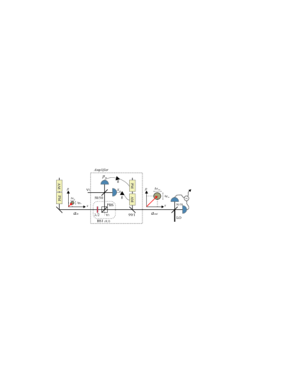
The amplifier proposed in this Letter is phase-insensitive, and, in principle, amplifies any input state at the quantum limit. In the following, we demonstrate experimentally the amplification of a particular quantum state, namely the coherent state. The experimental setup is shown in Fig. 1. The laser source was a monolithic continuous wave Nd:YAG laser at 1064 nm. A small part of the laser beam was tapped off to serve as an input signal to the amplifier and the rest was used as local oscillator beams. Since the output from a laser is not a perfect coherent state due to low frequency technical noise, we define our coherent state to reside at a certain sideband frequency which we chose to be 14.3 MHz, within a bandwidth of 100kHz. At this frequency the laser was found to be shot noise limited, and by applying modulations at 14.3 MHz (by independently controlling an amplitude and a phase modulator), the sidebands are excited and thus serve as a perfect coherent state.
The coherent state is then directed to the amplifier where it is divided by a beam splitter; the reflected part is measured and the transmitted part is displaced according to the measurement outcomes. Simultaneous measurements of the amplitude and phase quadrature are performed by combining the reflected signal beam with an auxiliary beam, , with a phase shift and balanced intensities. The sum and difference of the photocurrents generated by two high quantum efficiency photodiodes then provide the simultaneous measurement of amplitude and phase quadrature (this strategy is not shown explicitly in the figure). The outcomes are sent to electronic amplifiers with appropriate gains and then finally fed into independent modulators. The modulators are placed in an auxiliary beam which is coupled to the signal beam via an asymmetric beam splitter which transmits 99% of the signal and reflects 1% of the auxiliary beam, thus leading to a negligible small noise addition. After displacement, the amplified signal is directed into a homodyne measurement system for verification.
The performance of the system is characterized by measuring the spectral noise properties of the signal before and after amplification. Since the quadrature statistics of the involved fields are Gaussian, measurements of the first () and second moments () of two conjugate observables, such as the amplitude and phase quadrature, suffice to fully characterize the states. Both quadratures are measured at the sideband frequency using a standard homodyne detection techniques. To ensure consistent comparison between the input and output signal, these measurements are realized by the same homodyne detector.
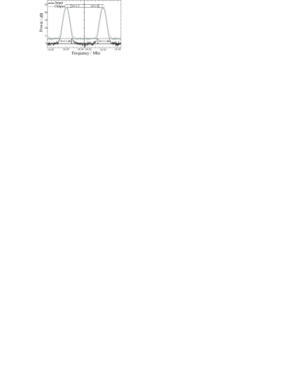
An example of a specific amplifier run is shown in Fig. 2. Here we set the beam splitting ratio to 1:2 in order to reach an optical gain of 1.5. The spectral densities of the amplitude and phase are shown over a 100 kHz frequency span for the input signal and the amplified output signal. Considering the whole span as a part of the quantum state, the heights of the peaks correspond to the coherent mean values whereas the noise floor can be regarded as the actual noise in the state. Therefore the amplification factor, which is roughly the difference between the input and output peaks, as well as the added noise, which is the difference between the shot noise limit and the noise floor, can be easily estimated. It is evident from the plots that additional noise has been added to the signal as a result of the amplification process.
To evaluate the noise figure, we estimated accurately the gain and the added noise at 14.3 MHZ. This was realized in a zero span measurement over 2 seconds by subsequently switching on and off the modulation. Moreover, to avoid erroneously underestimation of the noise power, all the measurement have been corrected for losses occurring in the homodyne detection. The total efficiency, including mode matching and photodiode quantum efficiency, has been carefully estimated to .
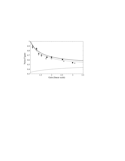
In Fig.3, we report the noise figure of our amplifier for a whole range of gains (corresponding to different transmission coefficients and optimized electronic gains). By comparing the experimental results with the ideal ones (calculated from Eq.(2) and indicated by the solid line), we clearly see that the amplifier operates close to the fundamental limit even for low amplification factors. The small deviation to the ideal amplifier performance is due to imperfections in the in-line homodyne detector and feedforward electronics. These limiting factors were partly overcome by paying special attention to the construction and alignment of the system. The efficiency of the homodyne detector amounted to 93% (95% photodiode efficiency and 99% mode overlap efficiency) and the electronic noise of the detectors was overcome by using newly designed ultra sensitive detectors. Taking these imperfections into account the theoretically expected noise figure is given by where is the overall efficiency of the detector system. This expression, which tends to the limit for high gains, is shown in Fig. 3 by the dashed line: it is in good agreement with the experimental results, demonstrating that basically no additional technical noise is invading the amplifying process.
The challenge of realizing such a quantum noise limited amplifier in the low gain regime is highlighted by considering the behavior of an amplifier that exhibits only two vacuum units of extra technical noise ( in Eq. (2)). As mentioned earlier and clearly illustrated by in Fig. 3, even such a small amount of background noise, which is quite common for amplifiers, leads to a strong deviation from the quantum noise limit at low gains.
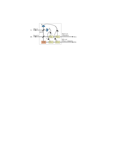
To complete the investigation of the system, we finally focus here on the existence of the phase conjugate amplified output state. This state, mirrored about the amplitude quadrature axis in phase space with respect to the input state, must be present in all amplifier to ensure unitarity caves82.prd . In downconverters, this mode is the idler output and thus easily accessible for further processing. However it is not always directly accessible: e.g. in a laser amplifier this mode is scattered into vibrational modes of the atoms. But where is the phase conjugate output in our scheme? It turns out that it can be extracted by the introduction of an entangled ancilla, as shown in Fig. 4. The amplifier settings are not changed (so equation (1) still holds), but now, in addition, one half of the entangled ancilla is injected into the empty port of the variable beam splitter and the other half is displaced according to the classical measurement outcomes. The amplification noise is not affected by this since the noise due of the entangled ancilla is cancelled out, as mentioned earlier. The electronic gains of the classical currents before displacement are and for the amplitude and phase quadrature, respectively. For perfect entanglement in the ancilla we find the following input-output relation for the additional output mode:
| (6) |
Eq. (5) and Eq. (6) mimic the ones of a downconverter and allow us to interpret and as being the input and output signal modes and and as being the input and output idler modes.
In conclusion, we have proposed and experimentally demonstrated that a phase-insensitive amplifier can be constructed from simple linear optical components, homodyne detectors and feedforward. Quantum noise limited performance was exhibited, in particular at low gains, only limited by inefficiencies of the in-line detection process. The fact that our amplifier exhibits nearly quantum noise limited performance at low gains suggests that it can be used to amplify non classical states (such as squeezed states and Schrodinger cat states) and still maintain some of their nonclassical features such as squeezing and interference in phase space. Furthermore, we believe that such an amplifier can find usage in the field of quantum communication, where optimal amplification of information carrying quantum states is needed partly to compensate for down stream losses of a quantum channel and partly to enable an arbitrary quantum cloning function braunstein . One particular cloning transformation of a coherent state was recently demonstrated with a fixed gain amplifier andersen05.prl .
We thank Norbert Lütkenhaus and Radim Filip for fruitful discussions. This work has been supported by the EU project no. FP6-511004 COVAQIAL.
References
- (1) W.H. Louisell, A. Yariv. and A.E. Siegman, Phys. Rev. 124 1646 (1961).
- (2) H.A. Haus, and J.A. Mullen, Phys. Rev. 128 2407 (1962).
- (3) C. M. Caves, Phys. Rev. D, 26 1817 (1982).
- (4) R.J. Glauber, in ”Frontiers in Quantum Optics” ed. by E.R. Pike and S. Sarker, Adam Hilger, Bristol and Boston (1986).
- (5) K. Shimoda et al., J. Phys. Soc. Jpn. 12, 686 (1957).
- (6) A. Yariv and T.W. Louisell, IEEE J. Quan. Elec. QE-2, 418 (1966).
- (7) H.P. Yuen and J.H. Shapiro, Opt. Lett. 4, 334 (1979).
- (8) Z.Y. Ou et al., Phys. Rev. Lett. 70 3239 (1993).
- (9) J.A. Levenson et al., J. Opt. Soc. Am. B 10 2233 (1993).
- (10) E. Knill et al., Nature 409, 46 (2001).
- (11) Levenson et al.levenson93.josab have demonstrated amplification close to the quantum noise limit for the amplitude quadrature. However, no measurement have been reported for the phase quadrature.
- (12) G. Björk and Y. Yamamoto, Phys. Rev. A 37, 4229 (1988).
- (13) P.K. Lam et al., Phys. Rev. Lett. 79, 1471 (1997).
- (14) R. Filip et al., Phys. Rev. A 71, 042308 (2005).
- (15) S.L. Braunstein et al, Phys. Rev. Lett. 86, 4938 (2001). J. Fiurasek, Phys. Rev. Lett. 86, 4942 (2001).
- (16) U.L. Andersen et al., Phys. Rev. Lett. 94, 240503 (2005).