theDOIsuffix \Volume51 \Issue1 \Month09 \Year2005 \pagespan3 \Receiveddate15 September 2005
Creating and probing long-range order in atomic clouds
Abstract.
Ultracold atoms interacting with the optical modes of a high- optical ring cavity can synchronize their motion. The collective behavior makes the system interesting for quantum computing applications. This paper is devoted to the study of the collective coupling. We report on the first observation of a collective dynamics and on the realization of a laser, the gain mechanism of which is based on collective atomic recoil. We show that, if the atoms are subject to a friction force, starting from an unordered distribution they spontaneously form a moving density grating. Furthermore, we demonstrate that a 1D atomic density grating can be probed via Bragg scattering. By heterodyning the Bragg-reflected light with a reference beam, we obtain detailed information on phase shifts induced by the Bragg scattering process.
keywords:
CARL, self-organization, Bragg scattering, ring cavity.pacs Mathematics Subject Classification:
04A251. Introduction
Ideally, a scalable quantum computer consists of registers of globally coupled two-level systems called qubits. To match the requirement of individual addressability of the qubits with the necessity of long-range correlations a periodic ordering of the qubits seems desirable. To name only two examples out of a huge number of proposals for quantum computers: Chains of ions confined in Paul-traps [1, 2] can be coupled by electrostatic repulsion through a common mode of their center-of-mass oscillation. Arrays of neutral heteronuclear molecules suspended in free space are coupled through long-range dipole-dipole interactions [3].
A proposal which is very similar to the ion chain idea consists in confining neutral atoms in the antinodes of a standing light wave formed by the two counterpropagating modes of a high-finesse ring cavity [4]. The atoms are periodically arranged in a one-dimensional optical lattice. The isolation of single atoms in standing waves and even their controlled shifting has impressively been demonstrated [5]. If several such atoms are confined in different antinodes, they can individually be addressed by probe beams. In fact, optical lattices draw an ever increasing attention, in particular in combination with quantum degenerate gases. E.g. Mott-insulators [6] may constitute good supports for quantum gates [7], and single atom transistors in optical lattices have been proposed [8].
However, ring cavities provide an even more important advantage, because they combine the scalability of optical lattices with a strictly uniform coupling and a strength which increases with the number of atoms in contrast to the situation in ion chains: The atoms all couple to the same light fields by scattering photons from one cavity mode into the counterpropagating one and receiving in return twice the photonic recoil. We have provided the proof that a collective dynamics can be driven in high-finesse ring cavities in recent experiments [9]. However these experiments deal with millions of thermal atoms, which is of course incompatible with individual addressability, and further research is needed to design an operating ring cavity quantum computer.
In this paper we present our research project, which has the goal to experimentally study collective dynamics in high-finesse ring cavities. A priori it is not so clear, that such a dynamics can take place, because perturbative effects known from laser gyroscopes may lock the relative phase of the counterpropagating modes and freeze the essential degree of freedom needed to couple the atomic motions. We found however that under certain circumstances a collective instability leads to self-amplification and exponential gain of a light field on one hand and to atomic bunching on the other. A careful study of our system enabled us to directly relate the observations presented in Ref. [9] to a phenomenon called the collective atomic recoil laser (CARL) postulated 10 years ago [10].
In the absence of dissipation for the motional degrees of freedom, the gain must remain transient. Consequently, we have observed a burst of light reverse to the pump beam direction. The light frequency increases in time as its amplitude vanishes. This burst is accompanied by a continuous acceleration of atoms. By introducing dissipation for their kinetic energy, we obtained a steady-state operation of the emitted light at a self-determined frequency. When the energy dissipation (or cooling) mechanism is limited to finite temperatures by some diffusion process, the appearance of a threshold is expected. We report here the observation of such a threshold: A minimum pump power is indeed necessary to start CARL action [11]. The threshold behavior of the cavity fields goes along with a phase transition in the atomic density distribution.
This paper is divided into three parts. In section 2, we outline the experimental apparatus and the sequence of our measurements. We emphasize that we have access to all relevant degrees of freedom characterizing our system: We monitor the dynamics of the cavity field by beating the field modes, record pictures of the atomic density distribution and probe the atomic velocity distribution by RIR spectroscopy. We present our observations and discuss the signatures of CARL in each of the monitored signals. We show that CARL is a transient phenomenon in the absence of dissipation for the external degrees of freedom. In contrast, in the presence of a friction force (experimentally realized by an optical molasses) a steady state is reached. In section 3 we draft a theoretical model that we compare to our observations. An analytic treatment for the ideal case of perfect atomic bunching enables us to find compact solutions for the probe field intensity and frequency. Numerical simulations of Langevin (or alternatively Fokker-Planck) equations at finite temperature show, that dissipation gives rise to a threshold behavior, which draws an analogy between CARL and conventional lasers. They also reveal that driven by a dissipative force, homogeneous atomic clouds can show collective instabilities spontaneously producing long-range order, atomic bunching and a thermodynamic phase transition reminiscent to self-organization mechanisms in networks of coupled oscillators. Section 4 focusses on the detection of long-range order via Bragg scattering. This part of the work is obviously motivated by our desire to unveil the most direct signature of CARL, which is atomic bunching. But we will see that the Bragg scattering method has also features, which are interesting in their own rights.
2. Collective coupling
A consequence of the development of new powerful techniques for optical cooling and trapping in the past decades is the ever increasing importance of the role assigned to the center-of-mass degrees of freedom in the interaction of matter with light. Prominent examples of how the motion of atoms can influence the scattering of light are the recoil-induced resonances (RIR) and the CARL. The RIR are observed [12, 13] as Raman transitions between momentum states. Two laser beams having different frequencies and crossing each other under a finite angle give rise to a moving standing light wave. Atoms moving synchronously to this wave can be scattered to other momentum states. The scattering process is monitored via power variations in the Raman beams. The spectroscopy of RIR is today routinely used to characterize the velocity-distribution of atomic samples [14].
The CARL has been conceived as a collection of two-level atoms driven by a single-mode pump field [15]. Under appropriate conditions, atomic density fluctuations (together with excitation and polarization fluctuations) induce a small amount of backscattering which interferes with the pump field and creates a weak traveling modulation wave. This wave, in turn, generates a weak density wave which, for appropriate values of the parameters, radiates and strengthens the backward scattered field in an avalanche process. The signature of CARL (and this distinguishes it from RIR) is thus an exponential growth of the backward field. In fact, atomic bunching and probe gain can arise spontaneously from fluctuations with no seed field applied [15]. An essential feature of the CARL model is the dynamical role played by the atomic motion. It must be included in the theoretical description to give proper account of recoil effects, which eventually are responsible for producing the organized atomic density modulation, or density grating, which is at the heart of the CARL process.
The CARL effect should emerge most clearly in cold atomic clouds in a collisionless environment [16]. Furthermore, large detunings of the lasers far outside the Doppler-broadened profiles of the atomic resonances are preferable. In this regime, excited states can safely be adiabatically eliminated, and effects from atomic polarization gratings not based on density variations, are avoided. Finally, to emphasize the role of exponential gain responsible for self-bunching, i.e. spontaneous formation and growth of a density grating, it is desirable not to seed the probe. The observation of a probe beam is then a clear indication for CARL [9]. Earlier attempts to observe CARL action have been undertaken in hot atomic vapors with near-resonant laser beams [17, 18]. They have led to the identification of a reverse field with some of the expected characteristics. However, the gain observed in the reverse field can have other sources [19, 20], which are not necessarily related to atomic recoil.
The best way to satisfy the specified conditions is to recycle the probe light in a very high finesse ring cavity. This permits to realize strong atom-field coupling forces very far from atomic resonances, i.e. in a regime where the atomic excitation plays no role. The large power enhancement inside a high-finesse cavity allows to confine the atoms inside the cavity mode-volume and thus to have quasi unlimited interaction times. The atomic cloud can be as cold as K. The densities are generally low enough to permit only few collisions per second. Far from resonance spontaneous scattering and thus radiation pressure is in most cases negligible.
Apart from ours, other experiments with cold atoms have recently found signatures for collective dynamics. Optical bistability has been observed in a high-finesse ring cavity [22, 23]. Spatial self-organization induced by collective friction force has been observed in a linear low-finesse cavity [21]. In both cases the underlying dynamics is however different from CARL [24].
2.1. Experimental setup
Ring cavities are particular in the following sense. The optical dipole force exerted by the light fields on atoms can be understood in terms of momentum transfer by coherent redistribution (via Rayleigh scattering) of photons between optical modes. In multimode configurations, e.g. counterpropagating modes of a ring cavity, the photon pumping can occur between different modes having independent photon budgets [25]. As a consequence, the scattering process conserves the total momentum of the atoms and photons, which is not the case for linear cavities, where backscattered photons end up in the same cavity mode. This implies that the atoms exert a noticeable backaction on the optical fields and that the atomic dynamics can be monitored as an intensity [26, 27] or a phase imbalance between the modes [9]. Consequently, in a ring cavity the scattering of a photon between the counterpropagating modes slightly shifts the phase of the standing wave.222 In the absence of spatially fixed backscattering objects the phase of the standing wave is free, in contrast to linear cavities where the phase is fixed by boundary conditions at the mirror surfaces. This shift, being strongly enhanced by a long cavity life time, is sensed by all atoms trapped in the standing wave. Consequently, the simultaneous interaction of the atoms with the two field modes couples the motion of all atoms [4, 28].
2.1.1. Ring cavity
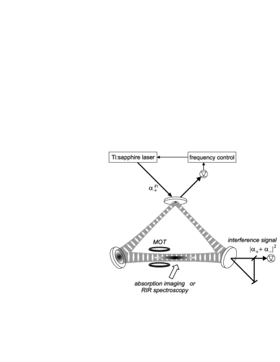
The ring cavity which is at the heart of our experiment (see Fig. 1) has a round trip length of mm and beam waists in horizontal and vertical direction at the location of the MOT of m and m, respectively [14]. This corresponds to the cavity mode volume mm3. For (linear) -polarization the two curved high reflecting mirrors have a transmission of , while the plane input coupler has a transmission of . Depositions of rubidium on the mirror surfaces actually reduce the finesse to , measured by cavity ring-down. This corresponds to an amplitude decay rate of kHz, where denotes the free spectral range. For -polarized light we found .
The optical layout of our experiment is shown in Fig. 1. A titanium-sapphire laser is double-passed through an acousto-optic modulator which shifts the laser frequency. The light beam is then mode-matched to one of the two counterpropagating cavity modes. The reflected light bears information about phase deviations between the laser and the intracavity light field. The light reflected from the cavity is fed back via a Pound-Drever-Hall type servo control to phase correcting devices. The phase corrections are made via a piezo transducer mounted to the titanium-sapphire laser cavity and via the acousto-optic modulator. The frequency deviations of the stabilized laser from the ring cavity resonance are much less than the linewidth of the ring cavity. Because the cavity mirrors have very different reflectivities for - and -polarization, we can switch from high to low finesse by just rotating the linear polarization of the injected laser beam. This tool is useful for tests comparing strong and weak coupling situations.
From the electric field per photon and the dipole moment [29], we calculate the atom-field coupling constant (or single-photon Rabi frequency) to be kHz, where MHz is the natural linewidth of the line of 85Rb. Therefore the coupling strength is much larger than the cavity decay rate, but still much smaller than the natural linewidth, .
In the following, we label the modes by their complex field amplitudes scaled to the field per photon, so that is the intracavity light intensity in the respective mode . The mode is pumped with the rate , where is the field amplitude of the incoupled laser beam (under the premise of perfect phase and impedance matching). On resonance and in the absence of any losses other then those included in , the cavity dramatically enhances the incident light power by [23]. The counterpropagating mode is populated out of by backscattering from atoms located inside the mode volume or from mirror imperfections. The light power outcoupled through a mirror with reflectivity is related to the intracavity power via .
2.1.2. Dipole trap for 85Rb
The ring cavity is located inside an ultrahigh vacuum recipient. We produce rubidium-85 atoms by a dispenser and collect them with a standard magneto-optical trap before transferring them into a TEM00 mode of the ring cavity field dipole potential. We typically load several million atoms into the dipole trap at temperatures of a few K and atomic peak densities of about cm-3. Density and temperature are monitored by time-of-flight absorption imaging.
The dipole force acting on the atoms and allowing for their confinement originates from intensity gradients in the cavity field. Let us assume that the field frequency is red-detuned from an atomic resonance , . Radial confinement is then ensured by the transverse Gaussian profile of the TEM00 mode. Axially, the atoms tend to concentrate around the free space waist of the cavity mode. The optical potential of the dipole force trap is, for a far detuned laser frequency, , to a good approximation given by , where is the local Rabi frequency. Obviously, the atom-field coupling strength , also called the cavity mode function, becomes inhomogeneous. is the one-photon Rabi frequency at the center of the trap, whose expression is given above.
Since rubidium exhibits a fine structure, we must consider the contributions of the and the line to the optical potential [29]:
In a running wave laser beam, , close to the center of the trap (i.e. on the cavity axis, , and within the Rayleigh length, ) the normalized mode function can be approximated by a harmonic potential . For a typical intracavity light power of W and a frequency detuning from the nearest atomic resonance of typically THz, we calculate an optical potential depth of mK. The radial and axial secular frequencies of the trap are kHz and Hz. An important quantity characterizing the coupling strength and used throughout this paper, the one-photon light shift, is typically on the order of .
Not too close to the resonance, the spontaneous scattering rate out of one beam is well approximated by
It decreases faster with detuning than the potential depth, so that for a chosen trap depth it is advantageous to work at higher detunings and higher laser intensities in order to avoid excessive heating by spontaneous scattering processes. For the parameters given above, we expect and . In this context the high-finesse optical cavity has the practical advantage that its large intensity enhancement [30] ensures a strong atom-field coupling even at laser detunings as large as nm.
Collisions are predicted to hamper the CARL process in buffer gas cells [31, 32], because they remix the atomic distributions faster than bunching through CARL dynamics. In contrast, for cold atoms the collision rate is generally quite small. At our typical densities and temperatures, we estimate a collision rate of min-1, where the average velocity and cm2 the elastic collision cross section [33]. This shows that on the time scale of our experiments (typically ms) the impact of collisions can be discarded.
2.1.3. Optical molasses
Some of our experiments are carried out in the presence of a so-called optical molasses. Technically, to create a molasses we use the laser beams of the magneto-optical trap, but without magnetic field gradients. Thus the molasses consists of three orthogonal pairs of counterpropagating polarized laser beams, which are tuned a few natural linewidths below the resonance. They traverse the dipole trap at angles of either or . The molasses light is linearly polarized at any location with a polarization vector winding about the molasses beam directions. Through these polarization gradients the atomic cloud is cooled well below the Doppler limit. The atomic motion inside an optical molasses is well described as being subject to a velocity-dependent friction force: The atoms are slowed down and move like in a viscous fluid, but there is no restoring force; the atoms are not trapped.
The friction force sensitively depends on the detuning of the molasses beams from resonance. Unfortunately, the dipole trap produces a light shift of the electronic states, which are coupled by the and transitions. The light shift increases the effective detuning of the molasses lasers by an amount equivalent to . The effective detuning thus gets inhomogeneous.333 As long as the dipole trap laser detuning greatly exceeds the hyperfine splittings of the ground and excited states, at least the optical potential is the same for all hyperfine and magnetic sublevels [29].
Another potential problem is the following: In the presence of magnetic fields the atoms are optically pumped towards fully stretched Zeeman states. Once the atoms are doubly spin-polarized, they preferentially interact with only one of the counterpropagating molasses beams, which leads to a radiation pressure imbalance. The resulting atomic acceleration interferes with signatures of CARL dynamics (see next sections). In practice, we take care to accurately compensate the magnetic fields.
Our main purpose in using optical molasses is to introduce friction to the system. However, the scattering of light by the molasses also leads to diffusion in momentum space, which limits the temperature to which the atoms are cooled. We will see in Sec. 3.2 that the interplay of friction and diffusion has a large impact on the dynamics of the system.
2.2. Signatures of collective atomic recoil lasing
A typical experimental sequence goes as follows [9]: After the dipole trap has been filled with atoms, a time of about ms is waited until the atoms have found their thermal equilibrium and form a homogeneous cloud. The CARL process is started by suddenly switching on the optical molasses. The molasses beams are extinguished again after some 100 ms.
The observables of our system are the field amplitudes and the atomic coordinates and . In order to clarify the interplay between these degrees of freedom, we measure the response of the coupled atom-cavity system to switching on and off the molasses. Three signals are monitored: First of all, we record the interference signal obtained from a frequency beat of the two counterpropagating ring cavity modes. Second, time-of-flight absorption images allow us to detect spatial displacements of the atomic cloud or to measure its temperature. Finally, we record RIR spectra of the atomic momentum distribution thus obtaining complementary information on the atomic cloud’s state of motion.
2.2.1. Beat note of field modes
The phase dynamics of two counterpropagating cavity modes is monitored as a beat signal between the two beams, which are outcoupled at one of the high-reflecting cavity mirrors (see Fig. 1) and phase-matched on a photodetector. Any frequency difference between pumped mode () and reverse (probe) mode () gives rise to a propagation of the standing wave inside the ring cavity, which translates into an amplitude variation of the beat signal,
The beat signal oscillates with the frequency .
Fig. 2 shows the time evolution of the beat signal. Initially, apart from a certain amount of noise, there is no discernable signal. But as soon as the molasses is irradiated at time s, strong oscillations appear with a fixed frequency. They persist for more than 100 ms. The oscillations do not arise, when the cavity is set up for low finesse.
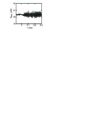
To understand this observation, we consider an atomic cloud irradiated by a pump laser. As long as the cloud is homogeneous, the pump light is not coherently backscattered, because the backscattered photons have random phases and interfere destructively. Tiny density fluctuations may however give rise to a small amount of net backscattering. The backscattering atoms are accelerated due to photonic recoil, and the backscattered light is red-detuned because of the Doppler effect. Together with the pump light the backscattered probe generates by interference a weak modulation of the intracavity light intensity, i.e. a standing wave fraction, which propagates in the same direction as the pump beam. If no other forces are applied, the accelerated atoms spread out in space and merge with the bulk of the homogeneous cloud; the fluctuation disappears and the probe decays. If however an optical molasses is irradiated, the acceleration is balanced by a friction force. The atoms now have time enough to probe the dipole potential of the standing wave and be pulled towards the potential valleys. Therefore they arrange themselves into a periodic pattern, which dramatically increases the backscattering efficiency due to Bragg reflection. The increased standing wave contrast in turn amplifies the tendency of the atoms to self-organize, and so on. Positive feedback results in exponential gain, only limited by the detuning of the probe mode from the cavity resonance (typically a few % of the pump power). The propagating standing wave drags along the atoms, which in turn haul the standing wave. The propagation velocity corresponds to an equilibrium between the acceleration force exerted by the coherent backscattering and the velocity-dependent friction force exerted by the molasses. The atoms behave like surfing on a self-generated standing light wave.
As soon as the optical molasses is turned off, the dipole force has no counterbalance. The standing wave and the atoms accelerate each other and start to run without bounds. The frequency difference between the pump and the reverse lasing mode continuously increases. Consequently, the beat signal oscillates faster and faster, and the contrast of the interference fringes gradually fades out, because the frequency of the backscattered light deviates more and more from the cavity resonance [see Fig. 3(a)]. However fringes are still visible after more than ms, which corresponds to 600 cavity decay times.
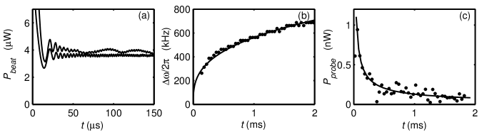
A Fourier analysis over consecutive time intervals of the beat signal reveals the gradual frequency increase of the oscillations , corresponding to an increasingly red-detuned probe beam [see Fig. 3(b)]. The decrease of the amplitude is visible in Fig. 3(c). In practice, we determine the probe beam power, , from the contrast of the beat signal (or the height of the peak in the Fourier spectrum), ,
2.2.2. Spectra of recoil-induced resonances
The above interpretation of the beat signal observation in terms of a propagating intracavity standing wave postulates an acceleration of the atomic cloud in the direction of the pump light. With the aim to provide evidence for an atomic motion, we map the atomic velocity distribution by RIR spectroscopy [14, 34]. Two laser beams in Raman configuration propagating within the ring cavity plane and enclosing a small angle are aligned nearly perpendicularly to the dipole trap. The Raman beams are tuned a few MHz blue to the line.
The RIR spectra are recorded a few ms after the molasses beams have been switched off and immediately after the pump laser has been interrupted, thus suddenly releasing the atoms from the dipole trap. The frequency of one Raman beam is frequency-ramped across a detuning range of kHz with respect to the other beam with a scan rate of kHz/s. The power transmission of the fixed-frequency Raman beam through the atomic cloud is recorded on a photodetector. Fig. 4(a) shows such a RIR spectrum.
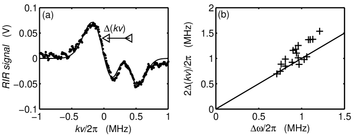
As pointed out in Ref. [14, 35, 36], the net rate for scattering photons between the Raman beams, , is proportional to the number of atoms , to the derivative of their velocity distribution , and to a constant which depends on the intensities of the Raman beams. The velocity class of atoms contributing to the signal is selected via , where and is the wavenumber of the RIR beams. The lineshape recorded in Fig. 4(a) suggests a bimodal velocity distribution for the CARL-accelerated cloud, which we model by a superposition of two distinct thermal ensembles having different atom numbers , different temperatures , and different center-of-mass velocities :
where . From a fit of this formula to the RIR signal exhibited in Fig. 4(a), we determine the relative atom number , the temperatures K and K, and the relative Doppler shift kHz. The actual values depend on the experimental settings. In particular we find that the relative Doppler shift increases with the time delay between molasses switch-off and RIR scan. By plotting the relative Doppler shift against the instantaneous CARL frequency independently extracted from a simultaneously recorded beat signal [see Fig. 3], we obtain the curve in Fig. 4(b). The data points correspond to different time delays. The equivalence nicely demonstrates that atoms are synchronously accelerated with the moving standing wave. On the other hand the bimodal feature of the velocity distribution shows, that a part of the cloud is apparently unaffected by the CARL dynamics.
2.2.3. Atomic transport
A Doppler-shift of kHz corresponds to an atomic velocity of cm/s and leads to macroscopic displacements of the atoms on the order of several mm after a few ms. To observe this displacement, we take absorption pictures of the atomic cloud after a few ms of undamped CARL acceleration followed by a short 1 ms free expansion period.444 For these measurements, the atomic bunching which precedes the CARL acceleration has not been realized by an optical molasses. Instead, the atoms were loaded into a standing wave dipole trap obtained by bidirectional pumping of the cavity [9]. This method concentrates the atoms within a smaller segment along the cavity axis and makes the axial displacement due to CARL more visible. Fig. 5(a) and (b) show pictures taken for CARL acceleration times of and ms, respectively. After 6 ms a spatial shift of the cloud is clearly visible.
In order to rule out that the atoms are simply shifted by radiation pressure, we repeat the measurement for weak coupling, i.e. by operating the ring cavity at low finesse and rising the pump power, so that the intracavity power and consequently the radiation pressure are unchanged. Under these conditions we do not observe a shift of the atomic cloud for acceleration times below ms.
The displacement can be estimated by integrating the formula (9) in Sec. 3.1, which describes the time dependence of the Doppler shift:
This yields mm, which agrees fairly well with the observation in Fig. 5. A bimodal structure of the spatial distribution, as observed in the velocity distribution, is not discernible because of the large axial extend for the cloud.
3. Creating long-range order
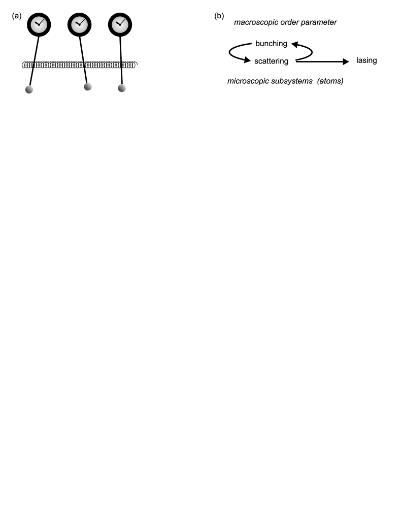
Driven by dissipative forces, certain categories of systems are able to spontaneously develop long-range order all by themselves without the need of periodic force fields. This self-organization is a very general phenomenon. Famous examples are populations of chorusing crickets or blinking fireflies, cardiac pacemaker cells, laser arrays or coupled arrays of Josephson junctions, rhythmic applause or simply Huygens pendulum clocks [see Fig. 6(a)], which synchronize their oscillations when attached to the same wall [37]. Self-synchronization is generally driven by the feedback interaction between a macrosystem and microsystems [see Fig. 6(b)]. A macroscopic order parameter defines the boundary conditions for microscopic processes. On the other hand, these microscopic processes can, if they act collectively, influence the order parameter. This global feedback can give rise to instabilities and to long-range order. In the case of CARL the order parameter is a bunching of atoms, the microscopic processes are light scattering events, and the long-range order shows up as lasing accompanied by a simultaneous formation of an atomic lattice [35].
The observations presented in the previous sections support this interpretation and confirm that collective interatomic coupling plays a prominent role in the dynamics of the atoms and the cavity modes. In the following sections we will briefly address some theoretical approaches to describe the dynamics quantitatively.
3.1. Analytic treatment for perfect bunching
The collective dynamics of atoms simultaneously coupled to light modes with and without the presence of a ring cavity has been studied by Bonifacio et al. [38], Gangl et al. [28] and Perrin et al. [31]. Our experiments deal with thermal clouds, so that the atomic coordinates may be treated classically. denotes the position of the atom and its momentum. Furthermore, due to its large mode volume, the cavity involves many photons in the dynamics, which allows us to describe the counterpropagating optical fields classically as well. The only remaining quantization is that of the internal atomic excitation, whose dynamics essentially follows two-level Bloch equations. However, for the very large detunings used in our experiments the internal degrees of freedom can be adiabatically eliminated [28, 31, 38]: At large detunings the field amplitudes and the atomic coordinates evolve much slower than the atomic excitation. Therefore, the time scales for the external and internal dynamics can be separated, which means that the atomic excitation is always in a (quasi-)stationary state and drops out of the equations of motion.
Furthermore, large detunings allow us to neglect any contribution from radiation pressure, . The interaction of the atoms with the ring cavity is then governed by the following set of equations of motion [28],555 Friction forces due to optical molasses are not considered here.
with . The equations have the following meaning: The first equation describes the modification of the field amplitudes by decay , detuning of the laser from the cavity resonance, or collective light shift (first term), by mutual scattering between the modes (second term) and external pumping (last term). Note that the mutual scattering amplitude is weighted with the location of the atoms modulo , i.e. the photon scattering balance depends on the atomic locations. The second equation states that the dipole force sensed by the atoms is caused by the scattering of photons between the counterpropagating modes.
The equations (7) must, in general, be solved numerically. Analytic solutions are only available for special cases. For example, under the assumption of perfect atomic bunching, for all , we can then replace all the individual atomic coordinates by a single pair of variables and .
As discussed by Gangl et al. [25] the dynamics of the CARL system critically depends on the detuning of the pump laser. An important point arising from experimental constraints is now the following: The pump mode is tightly phase-locked to the cavity. As discussed in Ref. [23], the presence of atoms inside the cavity mode volume may shift the cavity resonance, and this shift depends on the atomic bunching. Since the phase-lock continuously works to readjust the detuning (defined for the empty cavity) to the resonance (of the cavity filled with atoms), the detuning becomes a time-dependent variable, which follows the dynamics of the system. This fact needs to be considered by theories modeling our experiment, when it is operated in a parameter regime where the shift of the cavity resonances caused by the atoms, which is on the order of , exceeds the cavity linewidth . A good approach to model the impact of the phase-locking is to simply assume that the phase of the pump laser is equal to that of the locked mode . This assumption is good, because the bandwidth of our servo system largely exceeds all characteristic frequencies of the coupled dynamics. Without loss of generality we may fix these phases to zero, while the phase of the probe mode remains a dynamic variable,
The Eqs. (7) can approximately be solved, if we assume that the field amplitudes have no explicit time-dependence, . This assumption corresponds to an adiabatic elimination of inertial terms, which means that the standing wave and the atomic grating keep a fixed relative phase. It allows us to derive approximate solutions for the field amplitudes valid at long times, [11, 14, 36, 39],
where we introduced the abbreviation . These formulae have been fitted to the data in Fig. 3(b) and (c).666 It is interesting to compare the probe power dependence on the atom number to the dependence expected for superradiance (see Ref. [40]).
3.1.1. Radiation pressure
Far from atomic resonances, , the spontaneous scattering rate is many orders of magnitude lower than the coherent scattering rate . On the other hand, the photon flux of the pump beam is quite large. When we compare the radiation pressure force to the CARL force resulting from Eq. (7b),
we find that a power in the probe mode as low as is sufficient to ensure that the CARL force dominates. This shows that the radiation pressure can play a substantial role only at very long times, when the CARL acceleration has driven the probe mode very far out of resonance. But it does not take part in the acceleration process observed in Fig. 3(c). While the radiation pressure exerts a constant acceleration on the atoms, we observe in experiment a cubic root time-dependence of the CARL frequency.777 Note that poor atomic bunching can also reduce the CARL force up to a point where radiation pressure overtakes.
3.1.2. Phase-locking by imperfect mirrors
Phase-locking is a known problem of ring laser gyroscopes [41]. Any impurity located on the mirror surfaces, such as small dust particles, may scatter light into the reverse mode. Hence, a standing wave builds up, which adjusts its phase such that the scattering rate and thus the energy transfer into the reverse mode is maximized. The phase of the standing wave thus locks to the impurity.
The dipole force resulting from this standing wave can substantially alter the dynamics of atoms interacting with the cavity. In the worst case, the CARL acceleration is entirely inhibited, because the atoms are trapped in the standing wave caused by the mirror backscattering. In our ring cavity the phase fronts of the light fields hit the mirrors at angles of or . Macroscopic dust particles on the mirror surfaces traverse many phase fronts, so that in the average over several standing wave periods the net scattering between the modes should vanish.
However, the high finesse of the cavity amplifies even very small net scattering imbalances induced by microscopic irregularities (spatial noise). To see this, we describe the imbalance as originating from a distribution of point-like scatterers fixed at locations . With the scattering efficiency and assuming for simplicity , the stationary solution of Eq. (7a) reads
where . This equation shows that, at first sight counterintuitively, the intensity in the reverse mode increases, when the finesse of the mirrors is improved (or is reduced). The fraction measured in experiment, , corresponds to a collective coupling strength of about , which is smaller but in the same order of magnitude as the atom-field coupling used for observing CARL activity.
Furthermore, inserting the solution (11) into the expression for the dipole force (7b), we find that the phase of the backscattered light adjusts in such a way that the scatterer sits at half height on the edge of the resulting standing wave. In this configuration the backscattering rate is largest. However, any spatial extend of the scatterer’s size, expressed by a decrease of the bunching , will diminish this rate.
3.2. Simulations of atomic trajectories with friction and diffusion
The CARL equations (7) predict unlimited acceleration of the atoms and of the phase of the standing wave formed by the pump mode and the reverse mode. To balance this acceleration, we have introduced in our experiment an optical molasses. As discussed in Sec. 2.1.3, at low atomic velocities molasses are well characterized by a velocity-independent friction coefficient [42]. For the theoretical description we may thus supplement Eq. (7b) by a friction force .
Through the friction coefficient, the frequency and the amplitude of the probe beam depend on the settings of the molasses. This is verified experimentally [11]. However another prediction of this model is not verified. Simulations of Eqs. (7) including friction show a complete synchronization of the atomic trajectories for any set of parameters. After an amount of time, which depends on coupling strength, atom number and pump power, the atomic bunching tends to unity. This is due to the absence of any influence working to counteract the atomic ordering from the model, and contradicts the observation of a threshold observed in experiment [11].
A heating mechanism which is well-known to occur in optical molasses is momentum-diffusion. Momentum transfer to the atoms due to photonic recoil by scattering of light leads to a random walk of the atoms, which can be described as resulting from a random force [40]. Therefore, we describe the dynamics of our system by a set of Langevin equations. In general these cannot be solved analytically, and we have to numerically iterate them in time. For the sake of computational efficiency, we only calculate the trajectories of atoms. The molasses friction is strong enough to completely overdamp the atomic motion, so that we may adiabatically eliminate the atomic inertia and write [40],
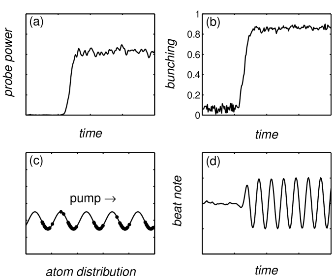
For the simulation, we assume that the atoms are irradiated by a pump laser and that there is initially one photon in the probe mode. We start with a homogeneous atomic cloud distributed around the waist of the cavity mode and having a thermal momentum distribution. Fig. 7 shows the time evolutions of the backscattered light intensity , the bunching parameter888 The bunching parameter measures the periodic arrangement of the atoms. It is also called the order parameter or Debye-Waller factor. , the spatial distribution of the atoms, and the interference signal . A short time delay after the optical molasses is switched on, the amplitude of the backscattered beam and the order parameter suddenly start to grow towards macroscopic values. The atoms arrange themselves into a periodic lattice, synchronize their velocities and, together with the standing wave, propagate in the pump beam direction [arrow in Fig. 7(c)]. In the same time, the beat signal starts to oscillate. The calculated trajectories reproduce quantitatively the experimental observations shown in Figs. 2 to 5.
3.2.1. Lasing threshold
The simulations confirm that, under the influence of an optical molasses and mediated by collective atomic recoil, the coupled atom-cavity system generates laser light. In the same time, the atoms self-organize into a periodic lattice, while breaking translation symmetry. The sudden appearance of a coherent radiation reminds a laser threshold, and the atomic ordering corresponds to a thermodynamic phase transition. To model the phase transition we have chosen an alternative approach. Instead of simulating single-atom trajectories, we derive from the Eqs. (12) a Fokker-Planck equation for the atomic density distribution. The solution of this equation reproduces the time evolution of the density distribution, and a linear stability analysis leads to simple analytic formulae describing the threshold conditions [40, 43].
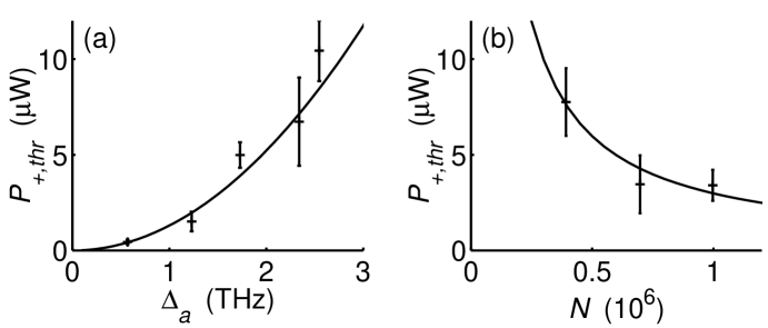
The calculated threshold behavior is observed in experiment: To trigger the CARL and obtain probe laser emission, a minimum pump laser power is needed. Below this threshold the order parameter disappears, far above threshold it approaches unity. The threshold power should obviously depend on some control parameters. Fig. 8 shows that, as expected, the threshold increases when the coupling strength is decreased, i.e. if the pump laser is tuned further away from the atomic resonance [11]. The threshold decreases when the atom number is increased.
The role of the molasses in the CARL dynamics is twofold: On one hand, the dissipation of energy permits to reach a steady-state. On the other hand, atomic momentum-diffusion processes, which are intrinsically connected to optical molasses, limit the equilibrium temperature. The interplay of dissipation and diffusion rules the thermodynamic phase transition, and gives rise to the observed threshold behavior of the CARL radiation.
3.2.2. Self-synchronization
The simplest model describing synchronization phenomena, known as Kuramoto model [44], considers ensembles of coupled limit cycle oscillators. It predicts the occurrence of spontaneous synchronization, when a critical number of oscillators is put together or when the coupling strength exceeds a critical value [45]. Under certain approximations, the Kuramoto model is also applicable to describe the CARL bunching of atomic trajectories [11]. However in the case of CARL, unlike for the Kuramoto model, the collective oscillation frequency is self-determined. The observed probe mode emits a new laser frequency, which only depends on global system parameters.
(a)
 (b)
(b)
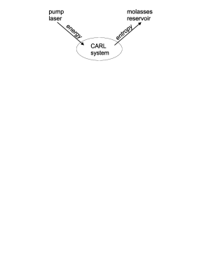
In fact, CARL represents in many respects an ideal system to study self-synchronization phenomena: First of all, free atoms are very simple systems, the behavior of which is almost completely understood. They are among the smallest entities, which can be handled and controlled with current technologies. Therefore, many of them can be joined together, thus experimentally realizing the thermodynamic limit to a good approximation. Furthermore, a truly universal coupling force (i.e. a force which couples any pair of atoms with the same strength, independently of their distance) is desirable, because the system is much easier to understand if local peculiarities do not affect the global dynamics. The CARL coupling is universal, because it is mediated by a light mode which is completely delocalized within the ring cavity. Finally, the coupling force should be sufficiently strong, so that the subsystems do not evolve independently from each other but execute collective actions. On the other hand, the coupling to the external world, e.g. reservoirs or pumps should be sufficiently weak to allow the system to develop a self-determined behavior.
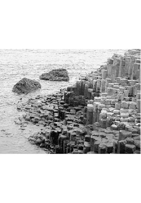
The atomic self-synchronization corresponds to a thermodynamic phase transition, where the control parameter is time. It is ruled by the competition between the dynamical coupling which generates order, and diffusion which is a source of disorder. It is however important to note that the system is never in thermal equilibrium. To maintain order, one has to constantly inject energy via the pump laser [see Fig. 9(a)]. The produced entropy is dissipated via the reservoir of the optical molasses. This introduces the irreversibility required in any lasing process. The transition towards a structure with a higher symmetry has certain analogies with the dissipative structures postulated by Prigogine [46] or with Haken’s synergetic systems [47], whose most famous examples are the Bénard structures. Those are regular patterns of convection flow arising in a heated fluid, and can e.g. be observed as frozen geological rock formations [see Fig. 9(b)].
4. Probing long-range order
The hallmark of collective atomic recoil lasing is atomic bunching. The CARL signatures presented in Sec. 2.2 are more or less indirect indications for the presence of bunching. There is however a way to probe atomic gratings directly, which is Bragg scattering.
Bragg scattering at three-dimensional near-resonant gaseous atomic gratings (called optical lattices) has been demonstrated 10 years ago by Birkl et al. and Weidemüller et al. [48, 49, 50]. In contrast to those experiments, our sample consists of an one-dimensional array of atomic clouds confined at the antinodes of a ring cavity standing wave, and the standing wave light is tuned very far from atomic resonances, so that the confining lattice potential is conservative and dissipative cooling forces are absent [51].
First attempts to employ the Bragg scattering method to monitor CARL bunching have not been successful. On one hand, this is due to the presence of atomic gratings not related to CARL. Spurious mirror backscattering (see Sec. 3.1.2) generates a stationary standing wave fraction, which is not generated by CARL dynamics of trapped atoms, but nevertheless forces the atoms into a partial alignment. To solve this problem, having in mind that CARL-bunched atoms always propagate along the cavity axis, we have developed a method of detecting moving lattices. On the other hand, the weak Bragg scattering efficiency of typically makes the detection of bunching a challenge. Fortunately, we have been able to show that suitable modifications of the experiment can dramatically increase the Bragg reflection [52] up to a point, where it should clearly be sufficient to detect CARL-bunching in future experiments.
4.1. Bragg scattering
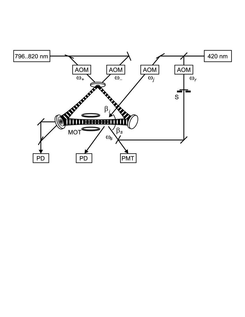
The setup for Bragg scattering is shown in Fig. 10, with the shutter S closed. We test the setup by generating an atomic lattice by imposing a periodic force field. To this end both counterpropagating modes of the ring cavity are pumped with the same light frequency, , so that the atoms arrange themselves in an optical grating. To probe the grating, light at nm resonant to the 5-6 transition is irradiated under the Bragg angle , and the reflected signal is recorded.
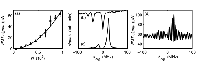
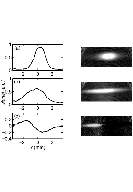
There are many obvious signatures of Bragg scattering: First of all, Bragg scattering works only for a well-defined angle of incidence. In fact the observed acceptance angle and the beam divergence of the reflected beam are both on the order of . Second, the reflected intensity should scale with the square of the atom number and not linearly, as one would expect for isotropic resonance fluorescence [51]. This is verified in Fig.11(a). Fig.11(b) shows a transmission spectrum of magneto-optically trapped atoms, which serves as a frequency reference. An example of a Bragg reflection spectrum is shown in Fig. 11(c). The spectrum is displaced due to the light-shift of the atoms in the dipole trap.
The trapped atoms sense a position-dependent dynamical Stark-shift, which results in inhomogeneous broadening of the atomic transitions. This broadening and also atomic heating induced by the Bragg laser limited the Bragg reflection efficiency in early experiments [51]. Subsequent experiments have shown that the Bragg scattering efficiency can be dramatically improved by tuning the probe laser to the line at nm. Efficiencies up to have been reached allowing for studies of subtle effects arising from the one-dimensional geometry of the optical lattice [53]. We have even observed signatures of a tricky interplay between multiple reflections and diffuse scattering in thick lattices [52].
4.2. Heterodyned Bragg spectra
The Bragg signals have been obtained on atoms confined in a standing wave, i.e. with bidirectional pumping of the ring cavity. The Bragg scattering technique can be refined to be sensitive to moving long-range order by heterodyning the Bragg-scattered light with a reference [51]. We test the idea by simulating the CARL behavior, i.e. we create a rotating standing wave inside the ring cavity by supplying different pump frequencies for the counterpropagating modes, . The frequencies are shifted by means of two acousto-optic modulators (AOM). The Bragg-reflected beam is phase-matched with a reference laser beam [the shutter (S) in Fig. 10 is opened], and the frequency beat is monitored on a photomultiplier (PMT). By means of another AOM the frequency of the reference beam is chosen such that the beat occurs at frequencies low enough to be resolved by our PMT. A fourth AOM ramps the Bragg beam frequency across resonance (see Fig. 10).
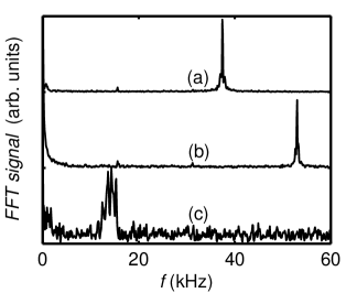
The observed beat signal between Bragg and reference beam is shown in Fig. 11(d). To evaluate the beat frequency, we show in Fig. 12 three Fourier spectra: (a) The beat of the counterpropagating cavity modes oscillates at the frequency ; (b) a reference interferometer (not shown in Fig. 10) measures the difference frequency , and (c) the frequency of the Bragg beat is . The fact that the Bragg-scattered light is obviously frequency-shifted by an amount corresponding to the Doppler-shift of the moving grating,
permits to determine the lattice propagation velocity with an accuracy better than 1% by measuring and .
Retardation effects resulting from unequal lengths of the interferometer arms lead to shifts in the recorded beat frequencies, as the laser frequency is scanned across resonance. The shifts can be corrected by inverting the scan direction. Furthermore, the Fourier spectrum of the Bragg beat in Fig. 12(c) shows asymmetric sidebands. These are artifacts arising from the presence of two hfs-resonances joint to the fact that the signal is amplitude- and phase-modulated by the frequency scan.
4.3. Measuring the Bragg scattering phase
As shown in the previous section, heterodyned Bragg scattering is well-suited not only to probe long-range order, but also to detect its motional dynamics. Hence, it constitutes an interesting tool to study the dynamics of CARL. But there is more information in the heterodyne signal, because it gives access to the scattering phase.
To see this, let us write the global response of the atomic cloud to an incident laser , as a complex scattering amplitude . The Bragg-scattered light amplitude is then given by . Heterodyning the Bragg-scattered light with a reference beam, , yields the signal
if . The amplitude and phase information are extracted by demodulating the beat signal with the reference frequency using two different phases. From these quadrature components we have determined the amplitude profile and the phase profile of the resonance [51]. The amplitude profile corresponds to the spectrum observed earlier by standard Bragg scattering. But the phase profile represents the first direct measurement of the phase-lag due to elastic scattering of light at an atomic cloud.
Under normal conditions phase measurements are not easy, because in thermal clouds Rayleigh scattering is Doppler-broadened by photonic recoil. In our case, the atoms are not only cold, but strongly confined; the Lamb-Dicke factor is about 100. Thus velocity-dependent recoil shifts are totally absent. Furthermore, Rayleigh scattering is normally weak (too weak to be heterodyned) because the atoms must be pumped at very low powers to avoid inelastic resonance fluorescence. Therefore, we gain a lot by resonantly enhancing the elastic peak by arranging the atoms into a grating and scattering at exactly the Bragg angle. To resume, two conditions are helpful for measurements of Rayleigh scattering phases, strong atomic confinement and atomic ordering.
5. Conclusion
With our work, we have shown that atoms interacting with the counterpropagating modes of a high-finesse ring cavity can exhibit collective dynamics, provided the interatomic coupling constant is sufficiently large as compared to the cavity linewidth. An important prerequisite for the possible use of ring cavities for quantum information processing [4] is thus experimentally verified. The epitome of collective behavior is without doubts the collective atomic recoil laser, the signatures of which we have detected for the first time. Previous attempts to observe CARL [17, 18] were based on a maximization of the coupling strength by tuning the pump laser close to an atomic resonance. In contrast, the use of a high-finesse ring cavity allowed us to obtain strong coupling at huge pump laser detunings, where no noticeable effect is expected from atomic polarization gratings which do not correlate to density gratings and where spontaneous scattering plays no role.
Another important result of our work is the proof that CARL can be made stationary. Optical molasses not only introduce very efficient dissipation forces, but also a coupling to a finite temperature reservoir giving rise to spontaneous self-synchronization beyond a critical pump power or coupling strength. Just like self-synchronization, which is a very common phenomenon known to give rise to macroscopic consequences such as large scale pattern formation, CARL is a purely classical phenomenon. It could in principle be observed with billiard balls, if there was a suitable coupling force at hand [54]. On the other hand, our system consists of atoms, which are microscopic particles. Therefore it ought to exhibit quantum features in some circumstances, in particular at ultra-low temperatures, where quantum statistics come into play. E.g. we may expect effects like quantized acceleration [55], superradiance [56] or quantum entanglement [57, 58].
The study of the quantum regime will be the challenge of our future research efforts. We plan to cool the atoms to very low temperatures, eventually even beyond the limit to quantum degeneracy. It is clear that optical molasses cannot be used to exert friction forces on Bose-Einstein condensates. However there are other dissipation mechanisms working in cavities, such as cavity-cooling [59]. This cooling mechanism is ultimately a consequence of the coupling of the cavity to a zero-temperature reservoir via the finite transmission of the mirrors; vacuum fluctuations couple to the optical cavity, while thermal photons are frozen out, which corresponds to a situation of having dissipation without diffusion. If a threshold behavior is observed under such circumstances, it is an interesting question to ask whether it is linked to a quantum phase transition. In practice, a controllable dissipation mechanism working for Bose-Einstein condensates would be an extremely valuable tool, especially for the study of decoherence mechanisms. Superfluidity makes the condensates insensitive to collisions, and other sources for dissipation are not available.
Regarding quantum information applications, the aptitude of ring cavities is conditionned to a totally coherent evolution of the atomic states and the absence of uncontrolled decoherence. This means that thermal motion must be completely avoided. The sequel of the ring cavity experiment in the ultralow temperature regime thus seems compulsory.
We are grateful for valuable discussions with R. Bonifacio, J. Javaloyes, R. Kaiser, G.-L. Lippi, M. Perrin, N. Piovella, A. Politi, H. Ritsch, and G.R.M. Robb. We acknowledge financial support from the Landesstiftung Baden-Württemberg.
References
- [1] J. I. Cirac and P. Zoller, Phys. Rev. Lett. 74, 4091 (1995).
- [2] H. C. Nägerl, et al. Phys. Rev. A 61, 23405 (2000).
- [3] D. DeMille, Phys. Rev. Lett. 88, 067901 (2002).
- [4] A. Hemmerich, Phys. Rev. A 60, 943 (1999).
- [5] W. Alt, D. Schrader, S. Kuhr, M. Müller, V. Gomer, and D. Meschede, Phys. Rev. A 67, 033403 (2003).
- [6] M. Greiner, O. Mandel, T. Esslinger, Th. W. Hänsch, and I. Bloch, Nature 415, 39 (2002).
- [7] O. Mandel, M. Greiner, A. Widera, T. Rom, T. W. Hänsch, and I. Bloch, Nature 425, 937 (2003).
- [8] A. Micheli, A. J. Daley, D. Jaksch, and P. Zoller, Phys. Rev. Lett. 93, 140408 (2004).
- [9] D. Kruse, Ch. von Cube, C. Zimmermann, and Ph. W. Courteille, Phys. Rev. Lett. 91, 183601 (2003).
- [10] R. Bonifacio, et al., Opt. Comm. 233, 155 (2004).
- [11] C. von Cube, et al., Phys. Rev. Lett. 93, 083601 (2004).
- [12] J. Guo, P.R. Berman, H. Dubetsky, and G. Grynberg, Phys. Rev. A 46, 1426 (1992).
- [13] J. Y. Courtois, G. Grynberg, B. Lounis, and P. Verkerk, Phys. Rev. Lett. 72, 3017 (1994).
- [14] D. Kruse, et al., Phys. Rev. A 67, 051802(R) (2003).
- [15] R. Bonifacio and L. De Salvo, Nucl. Instrum. Methods 341, 360 (1994).
- [16] P. R. Berman, Phys. Rev. A 59, 585 (1999).
- [17] G. L. Lippi, G. P. Barozzi, S. Barbay, and J. R. Tredicce, Phys. Rev. Lett. 76, 2452 (1996).
- [18] P. R. Hemmer, et al., Phys. Rev. Lett. 77, 1996 (1996).
- [19] W. J. Brown, J. R. Gardner, D. J. Gauthier, and R. Vilaseca, Phys. Rev. A 55, R1601 (1997).
- [20] W. J. Brown, J. R. Gardner, D. J. Gauthier, and R. Vilaseca, Phys. Rev. A 56, 3255 (1997).
- [21] A. T. Black, H. W. Chan, and V. Vuletic, Phys. Rev. Lett. 91, 203001 (2003).
- [22] B. Nagorny, Th. Elsässer, and A. Hemmerich, Phys. Rev. Lett. 91 , 153003 (2003).
- [23] Th. Elsässer, B. Nagorny, and A. Hemmerich, Phys. Rev. A 67, 051401(R) (2003).
- [24] P. Domokos and H. Ritsch, J. Opt. Soc. Am. B 20 , 1098 (2003).
- [25] M. Gangl and H. Ritsch, Eur. Phys. J. D 8, 29 (2000).
- [26] M. Kozuma, K. Nakagawa, W. Jhe, and M. Ohtsu, Phys. Rev. Lett. 76, 2428 (1996).
- [27] G. Raithel, W. D. Phillips, and S. L. Rolston, Phys. Rev. Lett. 81, 3615 (1998).
- [28] M. Gangl and H. Ritsch, Phys. Rev. A 61, 043405 (2000).
- [29] R. Grimm, M. Weidemüller, and Y. B. Ovchinnikov, Adv. At. Mol. Opt. Phys. 42, 95 (2000).
- [30] A. Mosk, S. Jochim, H. Moritz, Th. Elsässer, and M. Weidemüller, Opt. Lett. 26, 1837 (2001).
- [31] M. Perrin, Zongxiong Ye, and L. Narducci, Phys. Rev. A 66, 043809 (2002).
- [32] J. Javaloyes, G. L. Lippi, and A. Politi, Phys. Rev. A 68, 033405 (2003).
- [33] J. P. Burke Jr., C. H. Greene, and J. L. Bohn, Phys. Rev. Lett. 81(16), 3355 Oct (1998).
- [34] D. R. Meacher, D. Boiron, H. Metcalf, C. Salomon, and G. Grynberg, Phys. Rev. A 50, R1992 (1994).
- [35] Ph. W. Courteille, et al., AIP Conf. Proc. (ICAP’04) 770, 135 (2004).
- [36] D. Kruse, Selbstorganisation und Laseremission in kalten atomaren ensembles, PhD thesis, Universität Tübingen (2004), http://www.uni-tuebingen.de/ub/elib/tobias.htm.
- [37] S. H. Strogatz, Nature 410, 268 (2001).
- [38] R. Bonifacio and L. De Salvo, Appl. Phys. B 60, S233 (1995).
- [39] C. von Cube, Untersuchungen zum kollektiven atomaren Rückstoß-Laser, PhD thesis, Universität Tübingen (2005), http://www.uni-tuebingen.de/ub/elib/tobias.htm.
- [40] G. R. M. Robb, et al., Phys. Rev. A 69, 041403 (2004).
- [41] W. W. Chow, et al., Rev. Mod. Phys. 57, 61 (1985).
- [42] J. Dalibard and C. Cohen-Tannoudji, J. Opt. Soc. Am. B 6, 2023 (1989).
- [43] J. Javaloyes, M. Perrin, G.-L. Lippi, and A. Politi, Phys. Rev. A 70, 23405 (2004).
- [44] Y. Kuramoto, Progr. Theor. Phys. Suppl. 79, 223 (1984).
- [45] S. H. Strogatz, Physica D 143, 1 (2000).
- [46] G. Nicolis and I. Prigogine, Self-Organization in Non-Equilibrium Systems, Wiley, (1977).
- [47] H. Haken, Rev. Mod. Phys. 47, 67 (1975).
- [48] G. Birkl, M. Gatzke, I. H. Deutsch, S. L. Rolston, and W. D. Phillips, Phys. Rev. Lett. 75, 2823 (1995).
- [49] M. Weidemüller, A. Hemmerich, A. Görlitz, T. Esslinger, and Th. W. Hänsch, Phys. Rev. Lett. 75, 4583 (1995).
- [50] M. Weidemüller, A. Görlitz, Th. W. Hänsch, and A. Hemmerich, Phys. Rev. A 58, 4647 (1998).
- [51] S. Slama, et al., Phys. Rev. Lett. 94, 193901 (2005).
- [52] S. Slama, C. von Cube, M. Kohler, C. Zimmermann, and Ph.W. Courteille, Phys. Rev . A in preparation (2005).
- [53] S. Slama, et al., Phys. Rev. A in press (2005).
- [54] S. M. Wiggins, et al., Meas. Sci. Technol. 13, 263 (2002).
- [55] N. Piovella, M. Gatelli, and R. Bonifacio, Opt. Commun. 194, 167 (2001).
- [56] N. Piovella, R. Bonifacio, B. W. J. McNeil, and G. R. M. Robb, Opt. Commun. 187, 165 (1997).
- [57] M. G. Moore and P. Meystre, Phys. Rev. A 59, 1754 (1999).
- [58] N. Piovella, M. Cola, and R. Bonifacio, Phys. Rev. A 67, 013817 (2003).
- [59] V. Vuletic and S. Chu, Phys. Rev. Lett. 84, 3787 (2000).