Dipole Induced Transparency in drop-filter cavity-waveguide systems
Abstract
We show that a waveguide that is normally opaque due to interaction with a drop-filter cavity can be made transparent when the drop filter is also coupled to a dipole. A transparency condition is derived between the cavity lifetime and vacuum Rabi frequency of the dipole. This condition is much weaker than strong coupling, and amounts to simply achieving large Purcell factors. Thus, we can observe transparency in the weak coupling regime. We describe how this effect can be useful for designing quantum repeaters for long distance quantum communication.
pacs:
Valid PACS appear hereThe field of cavity quantum electrodynamics (CQED) has seen rapid progress in the past several years. One of the main reasons for this is the development of high quality factors optical micro-cavities with mode volumes that are less than a cubic wavelength of light Vuckovic and Yamamoto (2003). These high-Q cavities allow previously unattainable interaction strengths between a cavity mode and a dipole emitter such as a quantum dot.
There are a large number of applications that require strong interactions between a cavity and dipole emitter. These include methods for conditional phase shifts on single photons Duan and Kimble (2004), single photon generation Kuhn et al. (2002), and quantum networking Cirac et al. (1997). These applications either exploit modification of the dipole emission rate, or cavity spectrum, when the two systems are coupled. It is often perceived that in order to observe significant modification of the cavity spectrum, one must enter the so-called “strong coupling” regime. In this regime the interaction strength between the cavity and dipole is sufficiently large to fully split the cavity mode into a lower and upper polariton.
In this paper we show that the strong coupling regime is not required in order to see significant modification of the cavity spectrum. We consider a single cavity that is coupled to two waveguides and behaves as a resonant drop filter. When an optical field whose frequency is resonant with the cavity is sent down one waveguide, the drop filter cavity would normally transmit all the field from one waveguide to another. Hence, the waveguide would appear opaque at the cavity resonance because all the light would be dropped to the other port. We show that if one places a resonant dipole in the drop-filter cavity, the waveguide becomes highly transparent, even in the weak coupling regime. This transparency is caused by destructive interference of the two cavity dressed states. We refer to this effect as Dipole Induced Transparency (DIT), because of its close analogy to Electromagnetically Induced Transparency (EIT) in atomic media Harris et al. (1990).
The fact that we do not need strong coupling to modify the transmission of a waveguide is extremely important for the field of semiconductor CQED. Although photonic crystal cavities allow us to approach the regime of strong coupling with a single emitter, it is very difficult to fabricate cavities that have sufficiently high quality factors to reach the strong coupling regime. Things become even more difficult when we attempt to integrate these cavities with waveguides. The cavity-waveguide coupling rate must be sufficiently large that we do not lose too much of the field to leaky modes. At the same time, leakage into the waveguide introduces additional losses making strong coupling even more difficult to achieve. Thus strong coupling and efficient waveguide interaction require mutually conflicting demands on the performance of the cavity. Our result relaxes the constraint on strong coupling, allowing us to work in a practical parameter regime. To demonstrate the application of DIT, we conclude this paper by showing how it can be used to share entanglement between spatially separated dipoles, and to perform a full non-destructive Bell measurement on two dipoles. These operations are extremely useful for building quantum repeaters Briegel et al. (1998); Duan et al. (2001).
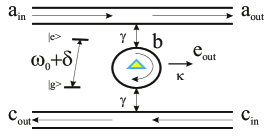
Fig. 1 shows a schematic of the type of system we are considering. A cavity containing a single dipole emitter is evanescently coupled to two waveguides. The cavity is assumed to have a single relevant mode, which couples only to the forward propagating fields (e.g. a whispering gallery mode). This system is equivalent to an input field reflecting off of a double-sided linear cavity, and our analysis equally applies to both cases. The dipole may be detuned by from cavity resonance, denoted , while is the vacuum Rabi frequency of the dipole. Both waveguides are assumed to have equal coupling rate into the cavity. This condition is known as critical coupling, and should result in the input field from one waveguide being completely transmitted to the other when Manolatou et al. (1999). When a dipole is placed inside the cavity, the cavity mode will split into two modes, the lower and upper polariton branches, that are shifted from the center frequency by the vacuum Rabi frequency. In the strong coupling regime, the vacuum Rabi frequency is sufficiently large that the cavity mode is split by more than a linewidth. In this regime, the cavity spectrum is no longer resonant with the input field, which now remains in its original waveguide. Our main interest, however, is in the weak coupling regime where the vacuum Rabi frequency does not exceed the cavity decay rate. In this case, the lower and upper polariton branches overlap significantly, and are still largely resonant with the input field. Nevertheless, the two branches can still destructively interfere in a narrow spectral region near zero detuning. This interference is analogous to the interference between the two dressed states of an atomic lambda system in Electromagnetically Induced Transparency.
To establish this, we begin with the Heisenberg operator equations for the cavity field operator and dipole operator , given by Walls and Milburn (1994)
| (1) | |||||
| (2) |
The operators and are the field operators for the flux of the two input ports of the waveguide, while is the operator for potential leaky modes. The bare cavity has a resonant frequency and an energy decay rate (in the absence of coupling to the waveguides). This decay rate is related to the cavity quality factor Q by . The parameter is the energy decay rate from the cavity into each waveguide. Similarly, the dipole operator has a decay rate , and is a noise operator which preserves the commutation relation. The output fields of the waveguide, and , are related to the input fields by Walls and Milburn (1994)
| (3) | |||||
| (4) |
Eq. 2 is difficult to solve because the field operator is multiplied by the time varying operator . However, we can significantly simplify the problem by looking at the weak excitation limit, where the quantum dot is predominantly in the ground state. In this limit, for all time, and we can substitute with its average value of . After deriving a solution, we will check the validity of this approximation.
Assuming the cavity is excited by a weak monochromatic field with frequency , we calculate the response of and using fourier decomposition. We assume that the cavity decay rate is much faster than the dipole decay rate, so that . This is a realistic assumption for a quantum dot coupled to a photonic crystal cavity, but does not necessarily apply in atomic systems coupled to very high-Q optical resonators. In this limit the waveguide input-output relations are given by the expressions
| (5) | |||||
| (6) |
where .
First, consider the case where the dipole is resonant with the cavity, so that . In the ideal case, the bare cavity decay rate is very small and can be set to zero. In this limit, when the field is resonant with the cavity and we have , as one would expect from critical coupling. In the opposite regime, when we have , so that the field remains in the original waveguide. This condition can be re-written as , where is the Purcell factor. Thus, in order to make the waveguide transparent, we need to achieve large Purcell factors. However, we do not need the strong coupling regime . When we can achieve transparency for much smaller values of . In this sense, our scheme is best suited for implementation in photonic crystal cavities coupled to quantum dots. The small mode volumes of photonic crystal cavities, coupled with the large oscillator strength of quantum dots, allows us to achieve the large Purcell factors needed for proper operation Englund et al. (2005); Badolato et al. (2005); Vuckovic et al. (2003). The above condition has another interpretation that can be borrowed from atomic physics. The critical atom number and critical photon number are defined as the number of atoms and photons in the cavity required to see modification of the cavity spectrum Kimble (1994). Our condition is equivalent to , so a single emitter is enough to modify the cavity. Also, because we automatically have .
We now go back and check the validity of our assumption that , which is equivalent to stating that . Using Equations 1-4, and assuming , we can show that on resonance, is equivalent to the condition . This condition basically states that the incoming photon flux must be much smaller than the modified spontaneous emission decay rate of the emitter (in the limit that the cavity decay is dominated by ), and is well satisfied in the operating regime we are working in.
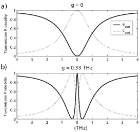
Fig. 2 plots the probability that transmits into and . We use realistic experimental parameters to create this plot. We set which is about a factor of 10 faster than for a cavity with a quality factor of . We set , a number calculated from FDTD simulations of cavity mode volume for a single defect dipole cavity in a planar photonic crystal coupled to a quantum dot Vuckovic and Yamamoto (2003). The dipole decay rate is set to , taken from experimental measurements Vuckovic et al. (2003).
Panel (a) of Fig. 2 considers the case where the cavity does not contain a dipole. In this case , representing a system where two waveguides are coupled by a cavity. This well known structure is often referred to as a drop filter. The width of the transmission spectrum for the drop filter is determined by the lifetime of the cavity, which in our case is dominated by .
When a dipole is present in the cavity, the result is plotted in panel (b). In this case, a very sharp peak in the transmission spectrum appears at . This peak is caused by destructive interference of the cavity field, which prevents the input field from entering the cavity. On resonance, all of the field is now transmitted through the waveguide instead of being dropped to the other port. The spectral width of the transmission peak is roughly equal to . It is important to note that the transmission is almost complete, even though is a factor of 3 smaller than the cavity decay rate of .

We now consider the effect of detuning the dipole. The transmission spectrum for several values of is plotted in Fig 3. Introducing a detuning in the dipole causes a shift in the location of the transmission peak., so that destructive interference occurs when the field frequency is equal to the dipole frequency. Thus, we do not have to hit the cavity resonance very accurately to observe DIT. We only need to overlap the dipole resonance within the cavity transmission spectrum.
The fact that we can strongly modify the transmission spectrum of a waveguide by the state of a dipole can be extremely useful for quantum information processing. As one example, we now present a way in which DIT can be applied to engineering quantum repeaters for long distance quantum communication. Quantum repeaters can be implemented all optically Pan et al. (2003); Waks et al. (2002), as well as using atomic systems Duan et al. (2001). One of the main problems with these proposals is that it is difficult to implement the full Bell measurement required for swapping entanglement. This leads to a communication rate that is exponentially decaying with the number of repeaters. More recent proposals incorporate interaction between nuclear and electron spins to implement the full Bell measurement Childress et al. . Here we propose a method for implementing entanglement, as well as a full Bell measurement on an atomic system using only interaction with a coherent field. This leads to an extremely simple implementation of a quantum repeater.
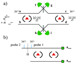
In panel (a) of Fig. 4 we show how DIT can be used to generate entanglement between two spatially separated dipoles. A weak coherent beam is split on a beamsplitter, and each port of the beamsplitter is then sent to two independent cavities containing dipoles. The waveguide fields are then mixed on a beamsplitter such that constructive interference is observed in ports and . Each dipole is assumed to have three relevant states, a ground state, an excited state, and a long lived metastable state which we refer to as , , and respectively. The transition from ground to excited state is assumed to be resonant with the cavity while the metastable to excited state transition is well off resonance from the cavity, and is thus assumed not to couple to state . The states and represent the two qubit states of the dipole.
When the dipole is in state , it does not couple to the cavity, which now behaves as a drop filter. Thus, we have a system that transforms and . This operation can be interpreted as a C-NOT gate between the state of the dipole and the incoming light. When the dipole is in a superposition of the two states, this interaction generates entanglement between the path of the field and the dipole state. After the beamsplitter, this entanglement will be transferred to the two dipoles. If the state of both dipoles is initialized to , it is straightforward to show that a detection event in ports or collapses the system to .
Another important operation for designing repeaters is a Bell measurement. Panel (b) of Fig. 4 shows how to implement a complete Bell measurement between two dipoles using only cavity waveguide interactions with coherent fields. The two cavities containing the dipoles are coupled to two waveguides. When a coherent field is sent down waveguide 1, each dipole will flip the field to the other waveguide if it is in state , and will keep the field in the same waveguide if it is in state . Thus, a detection event at ports and corresponds to a parity measurement. A Bell measurement can be made by simply performing a parity measurement on the two dipoles, then a Hadamard rotation on both dipoles, followed by a second parity measurement.
To understand why this works, consider the four Bell states and . The first parity measurement distinguishes the states from , since these two groups have opposite parity. After a Hadamard rotation on both dipoles, it is easy to verify that the states and are unaffected, while and , and thus flip parities. The second measurement will then distinguish between the states from and from , which completely distinguish the four Bell states. It is important to note that this measurement is non-destructive, in that after the measurement the state of the dipoles remains in the measured state.
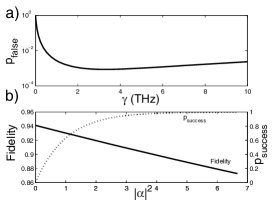
The performance of the Bell apparatus is analyzed in Fig 5. Panel (a) plots the probability that an odd parity state will falsely create a detection event in port , as a function of . The probability becomes high at large due to imperfect transparency. It also increases at small because of imperfect drop filtering. The minimum value of about is achieved at approximately 3THz. In panel (b) of Fig. 5 we plot both the fidelity and success probability of a parity measurement as a function of the number of photons in the probe field. The fidelity is calculated by applying the Bell measurement to the initial state , and defining the fidelity of the measurement as , where is the final state of the total system which includes the external reservoirs. The probability of success is defined as the probability that at least one photon is contained in the field. The fidelity is ultimately limited by cavity leakage, which results in “which path” information beaing leaked to the environment. This information leakage depends the strength of the measurement which is determined by the number of photons in the probe fields. Using more probe photons results in a higher success probability, but a lower fidelity. To calculate this tradeoff, we use previously described values for cavity and reservoir losses, and set the coupling rate to 4THz, which is where the probability of false detection is near its minimum. At an average of three photons, a fidelity of over can be achieved with a success probability exceeding . These numbers are already promising, and improved cavity and dipole lifetimes could lead to even better operation.
This work was funded in part by the MURI center for photonic quantum information systems (ARO/DTO Program DAAD19-03-1-0199), and a Department of Central Intelligence postdoctoral grant.
References
- Vuckovic and Yamamoto (2003) J. Vuckovic and Y. Yamamoto, App. Phys. Lett. 82, 2374 (2003).
- Duan and Kimble (2004) L. Duan and H. Kimble, Phys. Rev. Lett. 92, 127902 (2004).
- Kuhn et al. (2002) A. Kuhn, M. Hennrich, and G. Rempe, Phy. Rev. Lett. 89, 067901 (2002).
- Cirac et al. (1997) J. I. Cirac et al., Phys. Rev. Lett. 78, 3221 (1997).
- Harris et al. (1990) S. Harris, J.E.Field, and A. Imamoglu, Phy. Rev. Lett. 64, 1107 (1990).
- Briegel et al. (1998) H. J. Briegel, W. Dür, J. Cirac, and P. Zoller, Phys. Rev. Lett. 81, 5932 (1998).
- Duan et al. (2001) Duan et al., Nature 414, 413 (2001).
- Manolatou et al. (1999) C. Manolatou et al., IEEE J. Quant. Electron. 35, 1322 (1999).
- Walls and Milburn (1994) D. Walls and G. Milburn, Quantum Optics (Springer, Berlin, 1994).
- Englund et al. (2005) D. Englund et al., Phys. Rev. Lett. 95, 013904 (2005).
- Badolato et al. (2005) A. Badolato et al., Science 308, 1158 (2005).
- Vuckovic et al. (2003) J. Vuckovic et al., App. Phys. Lett. 82, 3596 (2003).
- Kimble (1994) H. J. Kimble, Cavity Quantum Electrodynamics (Academic, San Diego, 1994).
- Pan et al. (2003) Pan et al., Nature 423, 417 (2003).
- Waks et al. (2002) E. Waks, A. Zeevi, and Y. Yamamoto, Phys. Rev. A 65, 052310 (2002).
- (16) Childress et al., quant-ph/0502112.