Linear Optics C-Phase gate made simple
Abstract
Linear optics quantum logic gates are the best tool to generate multi-photon entanglement. Simplifying a recent approach Ralph_PG we were able to implement the conditional phase gate with only one second order interference at a polarization dependent beam splitter, thereby significantly increasing its stability. The improved quality of the gate is evaluated by analysing its entangling capability and by performing full process tomography. The achieved results ensure that this device is well suited for implementation in various multi photon quantum information protocols.
pacs:
03.67.-a, 03.67.Lx, 42.65.LmThe quantum computer is one of the most promising and desirable goals in quantum information science. Its implementation relies strongly on the capability to engineer entanglement in the quantum system of choice. For qubits it was shown that entangling gates (like the C-phase gate or the CNOT) together with single qubit operations are sufficient to create any kind of quantum network.
Photons are well suited for quantum information tasks, as their interaction with the environment is small guaranteeing low decoherence. While the creation of entangled photon pairs via spontaneous parametric down conversion became a standard technique, its control is still a major challenge, mainly due to low nonlinear interaction efficiencies. One solution to this problem is using linear optics components and introducing the nonlinearity via ancillary single photons and photon number resolving detectors KLM . Initial demonstrations showed that such gates can be implemented, once the necessary sources and detectors become available on a larger scale KLM-exp . Another solution, requiring much less resources becomes possible if one focuses on performing only a limited number of quantum logic operations. Then one can control the action of the gate by conditioning it to the detection of one photon in each of the output ports. This will occur only with a certain probability, which, however, might be larger than the one achieveable with the first method and equivalent resources. In particular, a controlled phase (C-Phase) gate was introduced recently Ralph_PG , which uses a combination of first and second order interference to obtain C-Phase action in 1/9 of the cases. Yet, since first-order interference requires stability of the setup on the order of less than the photon’s wavelength, for multi-photon experiments schmid more simple and stable implementations surely are desirable.
Here we introduce a linear optics C-Phase gate, which uses only a single two-photon interference at a polarization dependent beam splitter. The stability requirements are thereby relaxed to the coherence length of the detected photons () and can easily be fulfilled without additional stabilization equipment. To characterize the C-phase gate we first study the entangling capability of the gate by determining the fidelity and negativity of the output for four different input states. Second, we use linear quantum process tomography (QPT) linQPT ; Steinberg to analyze the gate operation. As imperfect interference reduces the quality of the gate and induces state-selective incoherence we had to account for the non-trace-preserving character of the gate. Instead of the usual maximum likelihood approach, we use prior knowledge of the intrinsic features of our setup, in order to obtain physical and easily understandable parameters for characterizing the gate and estimating its performance.
The ideal C-Phase gate acts on two-qubit input states
and applies a relative -phaseshift to the contribution VV only, such that
Here we encode the logical 0 (1) in linear horizontal (vertical ) polarization of single photons. denotes the amplitude of the -term (for the other terms accordingly).
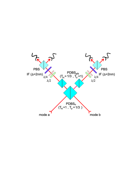
The application of the phase shift relies on second-order interference of indistinguishable photons at a polarization dependent beam splitter (PDBS) (Fig.1) HOM ; CST . Two input modes a and b are overlapped at . The transmission of for vertical polarization results in a total amplitude of for the output terms, as can be seen by adding the amplitudes for a coincident detection:
| (3) |
where () is the amplitude for transmission (reflection) of state in mode . Perfect transmission of horizontal polarization causes that no interference happens on the contributions and . As the absolute values of the amplitudes need to be equal for any input we still need to attenuate the contributions that include horizontal polarization. This is achieved by with the transmission for horizontal polarization and perfect transmission for vertical polarization in both output modes. All together we find a probability of to obtain a coincidence in the outputs and thus a gate operation with perfect fidelity.
Working with real components results in deviations from the theoretical derivation. A detailed calculation with arbitrary transmission and reflection amplitudes at and shows how their parameters influence the gate operation. In general we obtain from
| (4) |
where () are the transmission amplitudes of in mode a (b). To obtain the expected C-phase gate operation one has to fulfill several conditions, which give an insight in how the setup has to be built. First, , which is approximately achieved by slightly varying the angle of incidence at . Experimentally we reach a value of . Second, , which requires the reflection of the horizontal polarization at the overlap beam splitter to be zero. The third condition, , and , respectively, determines the setting for the attenuation at .
To experimentally test the gate operation we used photon pairs emitted from spontaneous parametric down conversion. A 2 mm thick BBO (-Barium Borate) crystal was pumped by UV pump pulses with a central wavelength of 390 nm and an average power of 700 mW from a frequency-doubled mode-locked Ti:sapphire laser (pulse length 130 fs). The pulsed operation is not necessary when working only with photon pairs, but as the gate is intended to work in multi-photon applications we preferred to characterize it for this mode of operation. The emission is filtered with polarizers to prepare input product states with high quality. We couple the photon pairs into single mode fibers for selection of the spatial modes. This guarantees identical beam modes which eases the alignment of spatial mode matching at . The spectral mode selection is improved via 2nm bandwidth filters behind the gate.
To ensure the same optical path length between the crystal and the
overlap beam splitter for both photons, one of the output couplers
of the single mode fibers is mounted on a translation stage. The
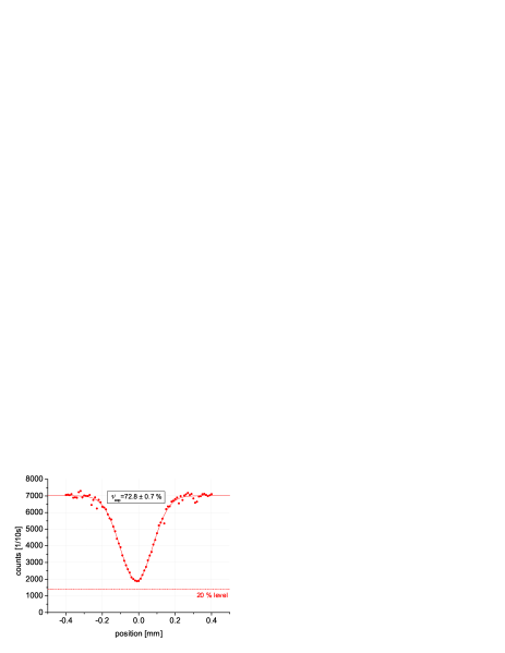
position of zero delay is determined from the minimum of the
coincidence rate for -input (Hong-Ou-Mandel HOM ,
”HOM”, Dip Fig. 2). In each output mode of the C-Phase
gate the polarization is analyzed via quarter and half waveplates
and a polarizing beam splitter with single photon avalanche photo
diodes. For the analysis of the final two-photon states the
coincidence count rates for each of the four contributions have to
be corrected for the different detector efficiencies. The errors
on all quantities are deduced from propagated Poissonian
counting statistics of the raw detection events and efficiencies.
The HOM-measurement shown in Fig. 2 also gives information about the indistinguishability of the photons at the PDBS. For large delay, the two photons are completely distinguishable due to their time of arrival. The probability to get a coincidence from a -input is then . In case of perfectly indistinguishable photons at zero delay, the probability drops to . The Dip-Visibility is defined by , where is the count rate at zero delay and at positions with big delay. From the above considerations we obtain a theoretical value of , and experimentally, applying least-square fit, we find . We call the overlap quality. One can conclude that the amount of additional -noise depends on the input, but is at maximum.
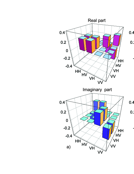
As a first step in the analysis of the performance of our gate we look at its capability to entangle. We choose , and , with and , as input product states and perform state tomography on the output states MOQ . We use linear tomography as the resulting matrices all have eigenvalues greater or equal -0.02, i.e., are almost physical without corrections. For an ideal C-phase gate one would obtain a maximally entangled output for these input states, for example
| (5) | |||||
The experimentally observed fidelities relative to the expected output states are all better . Fig. 3 exemplarily shows the experimental result for -input (). Note that for states with a fidelity larger than CHSH-inequalities are violated (CHSH ), which is the case for all of our examples. To quantify the entanglement we also calculated the logarithmic negativity — for all output states we find ().
For a complete characterization of an arbitrary unknown process one can use quantum process tomography (QPT). For QPT the process is represented by a superoperator which is decomposed in a linear combination of a basis of unitary transformations :
| (6) |
The matrix completely describes the process. In order to obtain all components , the normalized output density matrices for a tomographic set of, usually separable, input states are measured, in our case for the inputs ( , , , , , , , , , , , , , , , ). As the contribution of the -noise is input state dependent our process is non-trace-preserving. This means that the outcomes occur with different probabilities linQPT for the different input states :
| (7) |
We determine these probabilities from the diagonal entries of all measured output density matrices. The normalized density matrices together with the corresponding probabilities can be used to evaluate via Eq. (7) and (6). To account for the probabilistic nature of the gate an overall normalization is performed such that .
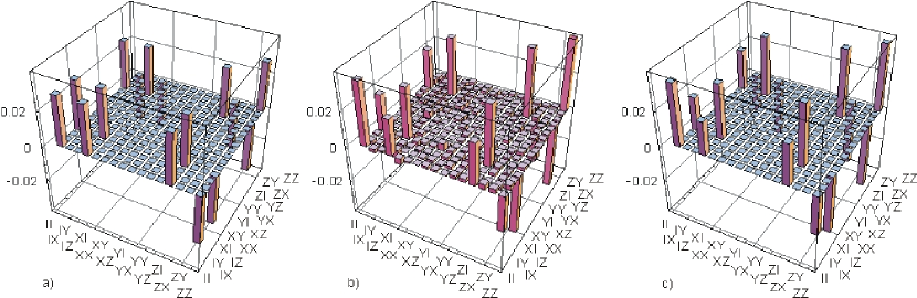
Fig. 4a shows the process matrix of the ideal linear optics phase gate. It represents the decomposition of the C-Phase gate into unitary operations, for our choice of resulting in
| (8) |
The four peaks in the diagonal of show the equal weights of the contributions, while the negative entries at the edges represent the negative sign at . This matrix now can be compared with the experimentally obtained one (Fig. 4b). Only the real parts are shown since the imaginary parts are close to zero (average ). As the introduced noise is not too big, the experimentally measured process matrix still demonstrates nicely the features of the gate operation. The main differences are the lower non-diagonal terms indicating reduced coherence in the system. From the estimated process tomography matrix we calculated a process fidelity of . Still, due to Poissonian counting statistics has non-physical, negative eigenvalues, and the above value has to be treated with care. To circumvent this problem one can use the maximum likelihood approach, where a physical process matrix is fitted to the observed data. Yet, the process is not really unknown to us and we can try to describe it via a theoretical model according to equation 4.
The transformation of the phase gate consists of interference between both photons transmitted or both photons reflected , where both and are matrices with components given by the coefficients of Eq. (4). For simplicity we assume and . reduces then to only one nonvanishing matrix element. The state dependent noise originates from the fact that interference occurs only with a probability according to the quality parameter and is incoherent otherwise, which finally yields
From this ansatz we obtain a model QPT-matrix by minimizing the sum of the absolute squared values of all the matrix elements of numerically (see Fig. 4c). The obtained quality value is in very good agreement with obtained from the fit to the HOM-dip. This indicates that it is indeed mainly imperfect overlap at the beam splitter which causes the state dependent noise. In order to compare the model with the real setup we calculate the fidelities between the predicted and the experimentally measured output density matrices obtaining an average value of F. An alternative model including depolarization in the gate did not significantly change the figure, the resulting white noise was negligible.
In conclusion we have presented a C-Phase gate acting on the polarization degree of photons. The gate relies only on one second order interference at a polarization dependent beam splitter and thus significantly simplifies previous approaches. We have demonstrated the entangling quality of the gate for various input states. A linear quantum process tomography allowed us to match a model of the gate to the experimental data. The resulting fit proofs the assumption, that the main deviation from optimal performance is due to distinguishability of incident photons at the overlap beam splitter. By means of further filtering this can be improved on the cost of count rate. The results ensure that this gate is ready to be used in various quantum information processing tasks such as generating multi photon entanglement or for complete Bell state analysis in quantum teleportation and entanglement swapping experiments.
We acknowledge stimulating discussions with A. Zeilinger. This work was supported by the Deutsche Forschungsgemeinschaft and the European Commission through the EU Project RamboQ (IST-2001-38864)
References
- (1) T.C. Ralph, N.K. Langford, T.B. Bell, and A.G. White, Phys. Rev. A 65, 062324 (2002); H.F. Hofmann and S. Takeuchi, Phys. Rev. A 66, 024308 (2002); J.L. O’Brien, G.J. Pryde, A.G. White, T.C. Ralph and D. Branning, Nature 426, 264 (2003); J.L. O’Brien et al., Phys. Rev. Lett. 93, 080502 (2004).
- (2) E. Knill, R. Laflamme, G.J. Milburn, Nature 409, 46-52 (2001).
- (3) T.B. Pittman, M.J. Fitch, B.C. Jacobs, and J.D. Franson, Phys. Rev. A 68, 032316 (2003); K. Sanaka, T. Jennewein, J.W. Pan, K. Resch, A. Zeilinger, Phys. Rev. Lett. 92, 017902 (2004); S. Gasparoni, J.W. Pan, P. Walther, T. Rudolph, A. Zeilinger, Phys. Rev. Lett. 93, 020504 (2004).
- (4) C. Schmid, et al., to be published; N. Kiesel, et al. to be published.
- (5) I.L. Chuang, and M.A.Nielsen, J. Mod. Opt. 44, 2455 (1997); J.F. Poyatos, and J.I. Cirac, P. Zoller, Phys. Rev. Lett. 78, 390 (1997).
- (6) M.W. Mitchell, C.W. Ellenor, S. Schneider, and A.M. Steinberg, Phys. Rev. Lett. 91, 120402 (2003).
- (7) C.K. Hong, Z.Y. Ou, L. Mandel, Phys. Rev. Lett. 59, 2044 (1987).
- (8) R.A. Campos, B.E.A. Saleh, and M.C. Teich, Phys. Rev. A 42, 4127 (1990).
- (9) D.F.V. James, P.G. Kwiat, W.J. Munro and A.G. White, Phys. Rev. A 64, 052312 (2001).
- (10) C.H. Bennett, G. Brassard, S. Popescu, B. Schumacher, J.A. Smolin, and W.K. Wootters, Phys. Rev. Lett. 76, 722 (1996).
- (11) Other parameters are determined as: , ,