Measurement of the electric polarizability of lithium by atom interferometry
Abstract
We have built an atom interferometer and, by applying an electric field on one of the two interfering beams, we have measured the static electric polarizability of lithium m3 with a % uncertainty. Our experiment is similar to an experiment done on sodium in 1995 by D. Pritchard and co-workers, with several improvements: the electric field can be calculated analytically and our phase measurements are very accurate. This experiment illustrates the extreme sensitivity of atom interferometry: when the atom enters the electric field, its velocity increases and the fractional change, equal to for our largest field, is measured with a accuracy.
An atom interferometer is the ideal tool to measure any weak modification of the atom propagation due to electromagnetic or inertial fields. The application of a static electric field is particularly interesting because it gives access to the electric polarizability and this quantity cannot be measured by spectroscopy which is sensitive only to polarizability differences (for a review on polarizability measurements, see reference bonin97 ).
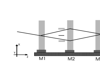
Several experiments with atom interferometers have exhibited a sensitivity to the electric electric field shimizu92 ; nowak98 ; nowak99 without aiming at a polarizability measurement and interferometers using an inelastic diffraction process have been used to measure the difference of polarizability between the ground state and an excited state rieger93 ; morinaga96 . A very accurate measurement of the atom polarizability requires that a well-defined electric field is applied on only one interfering beam and, up-to-now, such an experiment has been made only by D. Pritchard et al. ekstrom95 ; roberts04 by inserting a thin electrode, a septum, between the two atomic paths. We have made a similar experiment with our lithium atom interferometer, represented in figure 1 and we are going to describe its first results. With respect to the experiment of D. Pritchard et al., we have made several improvements: we have designed a capacitor with an analytically calculable electric field; we have a better phase sensitivity; finally our interferometer based on laser diffraction is species selective. Our experimental accuracy is presently limited by the knowledge of the mean atom velocity.
When an electric field is applied, the ground state energy decreases by the polarizability term . Therefore, when an atom enters the electric field, its kinetic energy increases and its wave vector becomes , with . The resulting phase shift of the atomic wave is given by:
| (1) |
is the atom velocity and the spatial dependence of the electric field along the atomic path is taken into account.
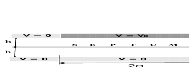
To know precisely the electric field along the atomic path, guard electrodes are needed, as discussed in ekstrom95 . We have developed a capacitor where guard electrodes are in the plane of the high voltage electrode, as shown in figure 2, which defines the notations. In this case, the field can be expressed analytically from the potential distribution in the plane of the high-voltage electrode. We give here only the results of the calculation which will be published elsewhere miffre05a .
The integral of along the septum surface can be written :
| (2) |
is the electric field of an infinitely long capacitor and the capacitor effective length is given by:
| (3) |
where exponentially small corrections of the order of are neglected. The atoms do not sample the electric field on the septum surface but at a small distance from the septum and we should add to the effective length a small correction proportional to . In our experiment, with m and mm, this correction is below and negligible.
The capacitor external electrodes are made of thick glass plates covered by an aluminium layer. The guard electrodes are insulated from the high voltage electrode by m wide gaps which have been made by laser evaporation and, under vacuum, we can operate the capacitor up to V. The glass spacers are glued on the external electrodes and the septum, made of a m thick mylar foil aluminized on both faces, is stretched and glued on the electrode-spacer assemblies. In our calculation, we assume that the potential on the high-voltage electrode is known everywhere but we ignore the potential inside the m wide dielectric gaps which may get charged. A superiority of our design is that these gaps are very narrow, thus minimizing the uncertainty on the capacitor effective length. Another defect is that the spacer thicknesses are not perfectly constant. We use equation (2) by replacing by its mean value , thus making a relative error of the order of which is fully negligible.
We have previously described our three-grating Mach-Zehnder atom interferometer delhuille02a ; miffre05 . The lithium atomic beam is a supersonic beam seeded in argon and we use Bragg diffraction on laser standing waves at nm. By choosing a laser detuned by about GHz on the blue side of the - transition of the isotope, the signal is almost purely due to this isotope (natural abundance %) and not to the other isotope . Any other species present in the beam, for instance lithium dimers or heavier alkali atoms, is not diffracted and does not contribute to the signal. In three-grating interferometers, the phase of the interference fringes depends on the -position of the gratings depending themselves on the position of the mirrors forming the three laser standing waves and this phase is given by , where is the laser wavevector and is the diffraction order. By scanning the position of mirror , we have observed interference fringes with an excellent visibility , up to %.
The capacitor is placed just before the second laser standing wave, with the septum between the two atomic beams. In the present work, we have used only the diffraction order so that the center of the two beams are separated by about m in the capacitor. When the septum is inserted between the two atomic paths, the atom propagation is almost not affected and we observe interference fringes with a visibility % and a negligible reduction of the atomic flux. To optimize the phase sensitivity, we have opened the collimation slit and the detection slit (see reference miffre05 ) with widths m and m, thus increasing the mean flux up to counts/s and slightly reducing the fringe visibility down to % (see figure 3). We have made a series of recordings, labelled by an index from to , with when is odd and with when is even with Volts. For each recording, we apply a linear ramp on the piezo-drive of mirror in order to observe interference fringes and data points are recorded with a counting time per channel equal to s. Figure 3 presents a pair of consecutive recordings. The high voltage power supply has stability close to and the applied voltage is measured by a HP model 34401A voltmeter with a relative accuracy better than .
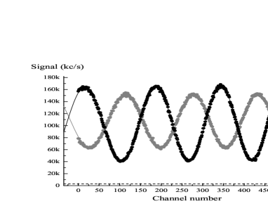
The data points have been fitted by a function , with where labels the channel number, represents the initial phase of the pattern, an ideal linear ramp and the non-linearity of the piezo-drive. For the recordings, , and have been adjusted as well as the mean intensity and the visibility , while, for the recording, we have fitted only , and , while fixing and to their value and from the previous recording. Our best phase measurements are given by the mean phase obtained by averaging over the channels. The error bar of these mean phases are of the order of mrad, increasing with the applied voltage up to mrad because of the reduced visibility.
The mean phase values values of the recordings present a drift equal to mrad/minute and some scatter around this regular drift. The drift is explained by the differential thermal expansion of the structure supporting the three mirrors: its temperature was steadily drifting at K/minute during the experiment. We have no explanation of the phase scatter, which presents a quasi-periodic structure: its rms value is equal to milliradian and unfortunately this error dominates our phase determination.
The phase shift due to the polarizability effect is taken equal to where the recording corresponds to the applied voltage : the average of the mean phase of the two recordings done just before and after is our best estimator of the mean phase of the interference signal in zero field. In figures 4 and 5, we have plotted the phase shift and the fringe visibility as a function of the applied voltage .


To interpret these results, we must take into account the velocity distribution of the lithium atoms, as the phase shift is proportional to . We assume that the velocity distribution is given by:
| (4) |
with the most probable velocity and is the parallel speed ratio. The traditional pre-factor haberland85 , which has minor effects, is omitted when is large. The interference signals can be written:
| (5) |
with . If we expand in powers of up to second order, the integral can be calculated exactly. This approximation is very good miffre05a but not accurate enough and we have calculated the integral (5) numerically. We have thus made a single fit for the phase and visiblility results, with two adjustable parameters: and . As shown in figures 4 and 5, the agreement is very good, in particular for , and we deduce a very accurate value :
| (6) |
The relative uncertainty % proves the coherence of our measurements. The parallel speed ratio is slightly larger than expected for our lithium beam, because Bragg diffraction is velocity selective.
From measurements made on our capacitor, we get mm and mm. We have measured the mean velocity using Doppler effect, by recording atom deflection due to photon recoil with a laser beam almost counterpropagating with the atoms. The uncertainty on the cosine of the angle is negligible (%) and we get m/s. We have also recorded the diffraction probability as a function of the Bragg angle, by tilting the mirror forming a standing wave. Using an independent calibration of the mirror rotation as a function of the applied voltage on the piezo-drive, we get a measurement of the Bragg angle rad corresponding to m/s. These two values are perfectly coherent and we take the mean velocity as their weighted average m/s. The theory of supersonic expansion can be used to check this result: the velocity of a pure argon beam given by (where K is the nozzle temperature and the argon atomic mass) must be corrected: the dominant correction is the velocity slip effect estimated to be % skovorodko04a and we get m/s in very good agreement with our measurements.
Finally, we get the lithium electric polarizability of 7Li m3, in excellent agreement with the previous measurements, m3 by Chamberlain and Zorn chamberlain63 in 1963 and m3, by Bederson and co-workers molof74 in 1974. Our result compares also very well with ab initio calculations of : most calculations predict values in the range m3 (see reference kobayashi97 and references therein).
With respect to the experiment done on sodium by D. Pritchard and co-workers ekstrom95 , we have made several important improvements:
Our capacitor design provides an analytical calculation of the integral along the atomic path. This property is helpful in minimizing the uncertainty on this quantity, through a better understanding of the influence of small defects. With an improved construction, we expect to reduce the uncertainty on this integral below %, the main limitation being due to the unknown potential in the dielectric gaps.
Thanks to a large signal and an excellent fringe visibility, the phase sensitivity of our interferometer is considerably larger than previously achieved. The accuracy on phase measurement is presently limited by the lack of reproducibility of the mean phase of the recordings. We hope to improve this reproducibility by stabilizing the temperature of the rail supporting the three mirrors. The consistency and accuracy of our phase measurements is proved by the quality of the fit of figure 4 and by the % uncertainty obtained for the measurement of . We have deduced the value of the electric polarizability with a % relative uncertainty dominated by the uncertainty on the mean atom velocity .
Our interferometer is species selective thanks to laser diffraction and this is also a very favorable circumstance. In his thesis, T. D. Roberts reanalyzes the measurement of sodium atom electric polarizability made by C. R. Ekstrom et al. ekstrom95 : he estimates that a weak contribution of sodium dimer to the interference signals might have introduced a non negligible systematic error in the result.
T. D. Roberts et al. roberts04 have devised a very clever technique to correct for the velocity dependence of the phase shift , so that they can observe fringes with a good visibility up to very large values. The present result proves that a very accurate measurement can be also made in the presence of an important velocity dispersion without any compensation of the associated phase dispersion, provided that the velocity distribution is taken into account in the analysis.
Finally, we would like to emphasize two very striking properties of atom interferometry. Our phase measurement consists in measuring the increase of the atom velocity when entering the field:
| (7) |
is extremely small reaching only for our largest field. Our ultimate sensitivity, close to a mrad phase shift, corresponds to !
In the capacitor, the atom wavefunction samples two regions of space separated by m with a macroscopic object lying in between and this situation extends over second, without any loss of coherence. This consequence of quantum mechanics remains surprising!
We thank J. C. Lehmann and J. F. Arribart from Saint-Gobain, J. F. Bobo and M. Nardone from LPMC and the staff of the AIME for their help in the construction of the capacitor. We thank CNRS SPM and Région Midi Pyrénées for financial support.
References
- (1) K. D. Bonin and V. V. Kresin, Electric-Dipole Polarizabilities of Atoms, Molecules and Clusters (World Scientific, 1997)
- (2) F. Shimizu, K. Shimizu and H. Takuma, Jpn. J. Appl. Phys. 31, L436 (1992)
- (3) S. Nowak, T. Pfau and J. Mlynek, Phys. Rev. Lett. 81, 5792 (1998)
- (4) S. Nowak, N. Stuhler, T. Pfau and J. Mlynek, Appl. phys. B 69, 269 (1999)
- (5) V. Rieger, K. Sengstock, U. Sterr, J. H. Müller and W. Ertmer, Opt. Comm. 99, 172 (1993)
- (6) A. Morinaga, N. Nakamura, T. Kurosu and N. Ito, Phys. Rev. A 54, R21 (1996)
- (7) C. R. Ekstrom, J. Schmiedmayer, M. S. Chapman, T. D. Hammond and D. E. Pritchard, Phys. Rev. A 51, 3883 (1995)
- (8) T. D. Roberts, A. D. Cronin, M. V. Tiberg and D. E. Pritchard, Phys. Rev. Lett. 92, 060405 (2004)
- (9) A. Miffre, M. Jacquey, M. Büchner, G. Trénec and J. Vigué, to be submitted.
- (10) R. Delhuille, C. Champenois, M. Büchner, L. Jozefowski, C. Rizzo, G. Trénec and J. Vigué, Appl. Phys. B 74, 489 (2002) 7
- (11) A. Miffre, M. Jacquey, M. Büchner, G. Trénec and J. Vigué, Eur. Phys. J. D 33, 99 (2005)
- (12) H. Haberland, U. Buck and M. Tolle, Rev. Sci. Instrum. 56, 1712 (1985)
- (13) P. A. Skovorodko, abstract submitted to Rarefied Gas Dynamics 24th Symposium (July 2004)
- (14) R. W. Molof, H. L. Schwartz, T. M. Miller and B. Bederson, Phys. Rev. A 10, 1131 (1974)
- (15) G. E. Chamberlain and J. C. Zorn, Phys. Rev. 129, 677 (1963)
- (16) T. Kobayashi, K. Sasagane and K. Yamaguchi, Int. J. Quantum Chem., 65, 665 (1997)