Fast and simple one-way Quantum Key Distribution
Abstract
We present and demonstrate a new protocol for practical quantum cryptography, tailored for an implementation with weak coherent pulses to obtain a high key generation rate. The key is obtained by a simple time-of-arrival measurement on the data line; the presence of an eavesdropper is checked by an interferometer on an additional monitoring line. The setup is experimentally simple; moreover, it is tolerant to reduced interference visibility and to photon number splitting attacks, thus featuring a high efficiency in terms of distilled secret bit per qubit.
Quantum key distribution (QKD) is the only method to distribute a secret key between two distant authorized partners, Alice and Bob, whose security is based on the laws of physics review . QKD is the most mature field in quantum information; nevertheless, there is still some work ahead in order to build a practical system which is reliable and at a same time fast and provably secure. This paper presents an important improvement in this direction. The quest for rapidity is the inspiring motivation of this system: the idea is to obtain the secret bits from the simplest possible measurement (here, the time of arrival of a pulse) without introducing lossy optical elements at Bob’s. Security is obtained by occasionally checking quantum coherence: in QKD, a decrease of coherence is attributed to the presence of the eavesdropper Eve, who has attacked the line and obtained some information on the bit values, at the price of introducing errors. Reliability is achieved by using standard telecom components; in particular, the source is an attenuated laser, and bits are encoded in time-bins, robust against polarization effects in fibers. In this paper, we first define the protocol and demonstrate its advantages: simplicity, and robustness against both reduced interference visibility and photon number splitting (PNS) attacks pns . Then, we present a first proof-of-principle experiment.
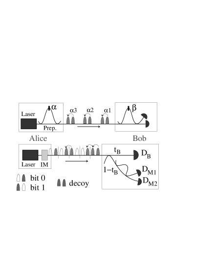
The protocol. To date, the most developed setups for practical QKD implement the Bennett-Brassard 1984 (BB84) protocol bb84 using phase encoding between two time-bins, as sketched in Fig. 1 Top (see review for a detailed description). The four states belonging to two mutually orthogonal bases are the where (bits 0 and 1 in the X basis) or (bits 0 and 1 in the Y basis). Bob detects in the X (Y) basis by setting (). Both bases correspond thus to an interferometric measurement. As a first step towards simplicity, we replace (say) the Y basis with the Z basis . Measuring in this basis amounts simply to the measurement of a time of arrival, and is thus insensitive to optical errors thales . Bits are encoded in the Z basis, which can be used most of the times, the X basis being used only occasionally to check coherence unknown .
In a practical QKD setup, the source is an attenuated laser: here, Alice’s source consists of a cw laser followed by an intensity modulator (IM), which either prepares a pulse of mean photon-number or blocks completely the beam (empty or ”vacuum” pulses) modelocked . The -th logical bit is encoded in the two-pulse sequences consisting of a non-empty and an empty pulse:
| (1) | |||||
| (2) |
Note that and are not orthogonal, due to their vacuum component; however, a time-of-arrival measurement, whenever conclusive, provides the optimal unambiguous determination of the bit value draft . To check coherence, we produce a fraction of decoy sequences ; while for BB84, one should produce the two states . Now, due to the coherence of the laser, there is a well-defined phase between any two non-empty pulses: within each decoy sequence, but also across the bit-separation in the case where bit number is 1 and bit number is 0 (a ”1-0 bit sequence”). Since we produce equally-spaced pulses, the coherence of both decoy and 1-0 bit sequences can be checked with a single interferometer (see Fig. 1, Bottom). And there is a further benefit: coherence being distributed both within and across the bit separations, Eve cannot count the number of photons in any finite number of pulses without introducing errors draft : in our scheme the PNS attacks can be detected inoue . To detect PNS attacks in BB84, one needs to complicate the protocol by the technique of decoy states, which consists in varying decoy .
The pulses propagate to Bob on a quantum channel characterized by a transmission , and are split at a non-equilibrated beam-splitter with transmission coefficient . The pulses that are transmitted (data line) are used to establish the raw key by measuring the arrival times of the photons. The counting rate is , where is the quantum efficiency of the photon counter. The pulses that are reflected at Bob’s beam-splitter go to the interferometer that is used to check quantum coherence (monitoring line). Indeed, when both pulses and are non-empty, then only detector can fire at time . Coherence can be quantified by Alice and Bob through the visibility of the interference
| (3) |
where is the probability that detector fired at a time where only should have fired. These probabilities are small, the average detection rate on the monitoring line being per pulse. Still, if the bit rate is high, meaningful estimates can be done in a reasonable time.
Let’s summarize the protocol:
-
1.
Alice sends a large number of times ”bit 0” with probability , ”bit 1” with probability and the decoy sequence with probability .
-
2.
At the end of the exchange, Bob reveals for which bits he obtained detections in the data line and when detector has fired.
-
3.
Alice tells Bob which bits he has to remove from his raw key, since they are due to detections of decoy sequences (sifting).
-
4.
Analyzing the detections in Alice estimates the break of coherence through the visibilities and associated respectively to 1-0 bit sequences and to decoy sequences, and computes Eve’s information.
-
5.
Finally, Alice and Bob run error correction and privacy amplification and end up with a secret key.
Estimate of the secret key rate. The performance of a QKD protocol is quantified by the achievable secret key rate . To compute this quantity, we need to introduce several parameters. The fraction of bits kept after sifting (sifted key rate) is with the counting rate due to photons defined above, the probability of a dark count, and here. The amount of errors in the sifted key is called quantum bit error rate (QBER, ). Moreover, this key is not secret: Eve knows a fraction of it. Some classical postprocessing (error correction and privacy amplification) allows to extract a key which is errorless and secret, while removing a fraction , where is binary entropy. Thence,
| (4) |
With this figure of merit, we can compare our scheme to BB84 implemented using the interferometric bases X and Y, as it is done today, with an asymmetric use of the bases such that (BB84XY). We require that all the visibilities are equal: in BB84XY, in our scheme — otherwise, Alice and Bob abort the protocol. Under this assumption, the QBER of BB84 is ; while in our scheme , independent of .
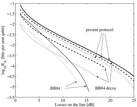
In order to estimate , we restrict the class of Eve’s attacks draft , waiting for a full security analysis. Because of losses and the existence of multi-photon pulses, Eve can gain full information on a fraction of the bits without introducing any errors. This fraction is either or , according to whether PNS attacks don’t or do introduce errors draft ; pns . Then Eve performs the intercept-resend attack on a fraction of the remaining pulses. In BB84XY, she introduces the error and gains the information . On the present protocol, the IR will be performed in the time basis, so . However, since we use only one decoy sequence, if Eve detects a photon in two successive pulses she knows what sequence to prepare; the introduced error is thence with the probability that Eve detects something in one pulse and nothing in the other. Plugging and into Eq. (4), we have as an explicit function of ; Alice and Bob must choose in order to maximize it. The result of numerical optimization is shown in Fig. 2 noteopt . As expected, the present protocol is more robust than BB84XY against the decrease of visibility.
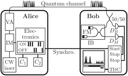
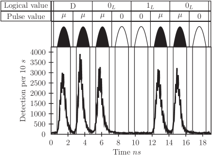
Proof-of-principle experiment. We show that a reasonably low QBER and good visibility can be obtained using standard telecom components in an implementation with optical fibers. The experimental setup is sketched in Fig. 3. The light of a cw laser (wavelength 1550 nm) passes through a intensity modulator (IM), which prepares the chosen pulse sequence. For simplicity, we send always the same 8-pulse sequence as shown in the figure, namely the string , where stands for a decoy sequence. The frequency of 434 MHz of clock defines the time between two successive pulses. The frequency of logical bits in a sequence is half of this frequency. The clock at 600 kHz generates the delay between two successive sequences. After the modulator, the light is attenuated by the variable attenuator (VA) in order to obtain for 5 dB loss in the quantum channel noteopt . The synchronization signal directly starts the time-to-digital converter (TDC) and triggers the detectors on Bob’s side. The detectors (data line) and (monitoring line) are opened with gates of 25 ns accepting the whole sequence, featuring quantum efficiency and a dark count probability per ns. Of course, due to the deadtime of the detectors, only one event per sequence and detector can be detected. The stop signal from arm is delayed, which allows to record the events of both detectors by the same TDC. The Michelson interferometer of the monitoring line has the same path length difference (46 cm of optical fibre) corresponding to the clock frequency. It is enclosed in an insulated, temperature controlled box (IB). The phase can be changed by changing the temperature. The interferometer (hence our entire setup) is polarization insensitive due to Faraday mirrors (FM) and features a classical fringe visibility of 99%.
The raw detection rate is of 17.00.1 kHz. The detection rate is limited by the detectors, due to the 10 s deadtime we have to introduce in order to limit afterpulses. With current detectors, the potential of an improved setup continuously sending pulses at , with optimized values for , and could only be exploited at long distances. Otherwise, one could use a detection system based on up-conversion and fast thin silicon detector thew05 .
The QBER for the pulse sequences ’10’ and ’01’ is obtained by considering the time windows of 1.7 ns as indicated in Fig. 4. The value is . The contribution of detector noise and afterpulses (which are rather high for the long gates and high repetition rates we are using) is estimated to be 4%; we attribute the remaining 1% to unperfect intensity modulation, mainly due to too slow electronics and to the jitter of the detectors.
The visibility of the interfering pulses on detector is measured by varying the phase (i.e the temperature) of the interferometer. The raw visibility is , if we consider 1.7 ns time windows. The net visibility, obtained deducing the dark counts and afterpulses is . We attribute the slight reduction of the visibility to a non perfect overlap of the interfering pulses due to timing jitter and fluctuations in the intensity modulation. However, this reduced visibility has no significant consequence on the secret key rate (Fig. 2). This tolerance in visibility simplifies the adjustment of the interferometers. With our basic thermal stabilization the interferometer needed to be readjusted only about every 30 minutes. Indeed, for our path length difference, a temperature stability of 0.01 K guarantees . Note, the higher , the easier becomes the stabilization of the interferometer.
Conclusion. We have introduced a new scheme for QKD and presented first experimental results. The scheme features several advantages: The data line is very simple, with low losses at Bob’s side and small optical QBER. The scheme is tolerant against reduced interference visibility and is robust against PNS attacks (thus allowing the mean photon number to be large, typically ). Finally, it is polarization insensitive. The existence of such a scheme shows that the main limiting parameter for practical quantum cryptography are the imperfections of the detectors.
We acknowledge financial support from the Swiss NCCR ”Quantum photonics” and the European Project SECOQC, and thank Avanex for the loan of an intensity modulator.
References
- (1) N. Gisin, G. Ribordy, W. Tittel and H. Zbinden, Rev. Mod. Phys. 74, 145 (2002)
- (2) G. Brassard, N. Lütkenhaus, T. Mor, B.C. Sanders, Phys. Rev. Lett. 85, 1330 (2000); N. Lütkenhaus, Phys. Rev. A 61, 052304 (2000)
- (3) C.H. Bennett, G. Brassard, in: Proceedings IEEE Int. Conf. on Computers, Systems and Signal Processing, Bangalore, India (IEEE, New York, 1984), pp. 175-179.
- (4) Our data line is that of a classical communication channel, but with a photon counter. The same line is used in a different QKD protocol: T. Debuisschert, W. Boucher, Phys. Rev. A 70, 042306 (2004).
- (5) H.-K. Lo, H.F. Chau, M. Ardehali, J. Cryptology 18, 133 (2005); see also quant-ph/9803007.
- (6) N. Gisin et al., quant-ph/0411022
- (7) A similar argument applies to a different protocol: K. Inoue, T. Honjo, Phys. Rev. A 71, 042305 (2005)
- (8) W.-Y. Hwang, Phys. Rev. Lett. 91, 057901 (2003); X.-B. Wang, quant-ph/0410075; H.-K. Lo, X. Ma, K. Chen, quant-ph/0411004.
- (9) Alternatively, the source could be a pulsed mode-locked laser followed by a pulse-picker.
- (10) If dark counts can be neglected (), the optimization can be done analytically: for the present protocol, ; for BB84, with, and without decoy states, where . For simplicity, in the optimization we have taken for both protocols, although this may be technically harder to achieve in BB84 because there are more optical components.
- (11) R. Thew et al., in preparation.