Dimensional Crossover in Bragg Scattering from an Optical Lattice
Abstract
We study Bragg scattering at 1D optical lattices. Cold atoms are confined by the optical dipole force at the antinodes of a standing wave generated inside a laser-driven high-finesse cavity. The atoms arrange themselves into a chain of pancake-shaped layers located at the antinodes of the standing wave. Laser light incident on this chain is partially Bragg-reflected. We observe an angular dependence of this Bragg reflection which is different to what is known from crystalline solids. In solids the scattering layers can be taken to be infinitely spread (3D limit). This is not generally true for an optical lattice consistent of a 1D linear chain of point-like scattering sites. By an explicit structure factor calculation we derive a generalized Bragg condition, which is valid in the intermediate regime. This enables us to determine the aspect ratio of the atomic lattice from the angular dependance of the Bragg scattered light.
pacs:
42.50.Vk, 42.55.-f, 42.60.Lh, 34.50.-sBragg scattering is a widely used method for observing and analyzing periodic structures. Introduced by von Laue and Bragg more than 80 years ago, it has become an inestimable tool in solid state physics and crystallography Wollan32 . In quantum optics the advent of powerful laser cooling and trapping techniques has led to the realization of optical lattices, i.e. periodic arrangements of ultracold atoms confined to arrays of optical potentials formed by one or more standing light waves Jessen96 . Optical Bragg scattering from 3D optical lattices has been first investigated by Birkl et al. and Weidemüller et al. Birkl95 ; Weidemuller95 . Bragg scattering from a 1D optical lattice has been realized recently for the first time within our group Slama05 . At present, optical lattices play an important role in many experiments. The observation of Bloch oscillations BenDahan96 and the realization of Mott insulators Greiner02 and Tonks-Girardeau gases Paredes01 in degenerate atomic quantum gases are prominent examples. One-dimensional optical lattices have interesting effects on the collective behavior of Bose-Einstein condensates Inguscio01 . Bragg diffraction represents a powerful tool for sensitively probing the properties of such optical lattices. A method for phase-sensitive Bragg spectroscopy based on heterodyning the Bragg-reflected light with a reference light field has recently been presented by our group Slama05 .
In this paper we show how the Bragg condition well-known from diffraction experiments with X-rays at solids has to be modified, if the size of the crystal is limited. This is done by an explicit calculation of the structure factor. We experimentally test our model by probing the angular dependence of the Bragg condition on a 1D optical lattice. This enables us to determine the aspect ratio of the atomic lattice. We find that our optical lattice occupies an intermediate position between a linear chain of point-like scatterers and a stack of extended homogeneous reflection layers reminiscent to a dielectric mirror.
The optical layout of our experiment is shown in Fig. 1. It consists of an optical cavity and a setup for Bragg scattering. The cavity input coupler has a curvature cm and a transmission , and the high reflecting mirror is plane and has a transmission . The measured finesse of the cavity is , and the beam diameter at its center is m. The light of a titanium-sapphire laser operating at nm is coupled and frequency-locked to the cavity, thus forming a standing wave with periodicity . The intracavity power is W. Between and 85Rb atoms can be loaded from a standard magneto-optical trap into the standing wave, which is red-detuned with respect to the rubidium line. From absorption spectroscopy of the atomic cloud we roughly estimate that about antinodes are filled with atoms. Typically the temperature of the cloud is on the order of a few K; we noticed in earlier experiments Kruse03 ; Nagorny03 that the temperature of the cloud tends to adopt a fixed ratio with the depth of the dipole trap. Therefore, the spatial distribution of the atoms does not vary much with the chosen potential depth. For the trap in this setup we measured . From this we derive the rms-size of the atomic layers, nm in the harmonic approximation of the trapping potential. The radial size is m and the mean density can be adjusted between and cm-3.
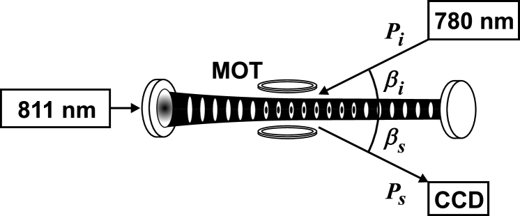
The light used to probe the Bragg resonance is generated with a near infrared laser diode operating at nm. The frequency is tuned to the Rb line. The laser light is collimated to a beam waist of m before crossing the standing wave under an angle of . The irradiated light intensity is, with a total laser power of , far below the saturation intensity. Some time after loading the atoms into the standing wave the Bragg light beam is switched on. The light reflected from the atoms, (several nW), is detected with a CCD camera (Sony XC55), from which we get the intensity profile of the reflected light beam. This allows us to determine the reflection angle .
The Bragg condition follows from energy- and momentum conservation. Our standing wave dipole trap represents a 1D optical lattice with the lattice constant . The Bragg condition requires that the difference beween the scattered and the incident wavevectors, , coincides with a vector of the reciprocal grating , where . This implies
| (1) | ||||
The first equation is the condition for constructive interference of light reflected from subsequent scattering planes. The second equation arises from the fact that the radial atomic distribution is nearly homogeneous on the length scale of a wavelength. Together the two equations (1) yield
| (2) |
The efficiency of Bragg scattering depends critically on the angle of incidence . In order to probe the Bragg condition has to be varied over the value given by (2). Experimentally it is easier to vary the wavelength of the lattice laser , while the angle of incidence is kept fixed. To resonantly enhance the Bragg scattering, which otherwise would be neglegibly small, we tune the laser to the transition between and at nm with a natural linewidth of MHz. During the Bragg pulse sequence the repumping laser of the magneto-optical trap is kept on to avoid optical pumping into the ground state level.
The Bragg condition (1) implies two equations. Their claim is that for infinitely extended layers the angle of incidence and the reflection angle are equal and their cosines sum up to a fixed value. Both conditions are fulfilled, if the incident beam is shone under the Bragg angle given by (2) onto the atomic cloud. However when the angle of incidence is misaligned from the Bragg condition, one of these equations must be violated. Which one it is depends on the form of the atomic cloud. For radially extended clouds, we expect the two angles to be equal. In contrast, for long lattices (many layers) we expect that the sum of the angles stays constant. This can be illustrated with a calculation of the structure factor . Its absolute square is proportional to the scattered light intensity Coley01 ,
| (3) |
where is the atomic density within the lattice. We assume for each layer a Gaussian density distribution, which is well fulfilled in the harmonic approximation
| (4) |
The atoms are spread over layers of the lattice yielding an overall density distribution, which can be expressed as a convolution of the single site distribution with a sum of -functions,
| (5) |
| (6) |
The sum in (6) can be written as an Airy function
| (7) |
Experimentally relevant is first order scattering , for which the Airy function reaches a maximum with an approximated full width at half height of . For this approximation the cosines of the Airy function are expanded up to sixth order and The integrals in equation (6), one for every direction in space, are evaluated by Gaussian functions, for example
| (8) |
On Bragg resonance and . The full width at half height of and is given by . The Debye-Waller factor can be regarded as a constant attenuation of the structure factor within the above calculated range .
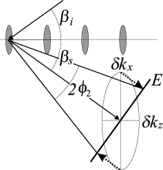
The above calculated widths correspond to a certain solid angle , into which the Bragg-scattered light is emitted. The solid angle is given by , with the half opening angles . The situation is simple for the -direction, which is orthogonal to the scattering plane: . Within the scattering plane the widths and have to be projected onto a plane orthogonal to the emission direction, as shown in figure 2. The opening angle is then determined by the maximum of the two projections: The total result for the solid angle is therefore
| (9) |

In our case , i.e. the lattice behaves more like a linear chain of point-like scatterers. We find srad. We now calculate the direction of the emitted light beam. To this purpose we assume that the structure factor is an ellipsoid with Gaussian profile
| (10) |
and search for the angle , for which the structure factor gets largest on the intersection of the ellipsoid with the Ewald sphere (see Fig. 3). Implicitly contained is the assumption that the scattering is elastic by setting . The part vertical to the scattering plane (-direction) is omitted, because its effect on the scattering angle is negligible. Maximization of equation (Dimensional Crossover in Bragg Scattering from an Optical Lattice), , results in
| (11) |
Two limiting cases are interesting: For small aspect ratios, , we recover the Bragg condition
| (12) |
For large aspect ratios, , we get the second of the equations (1).
| (13) |
The impact of a finite structure factor can be seen in experiment. There are two signatures: 1. The reflection angle should deviate from the values predicted by the classical Bragg condition (1). 2. The efficiency of the Bragg scattering should exhibit a narrow resonance upon tuning the lattice constant via . The width of this resonance is given by the radial spread of the layers within the lattice. These signatures are observed in the following measurements.
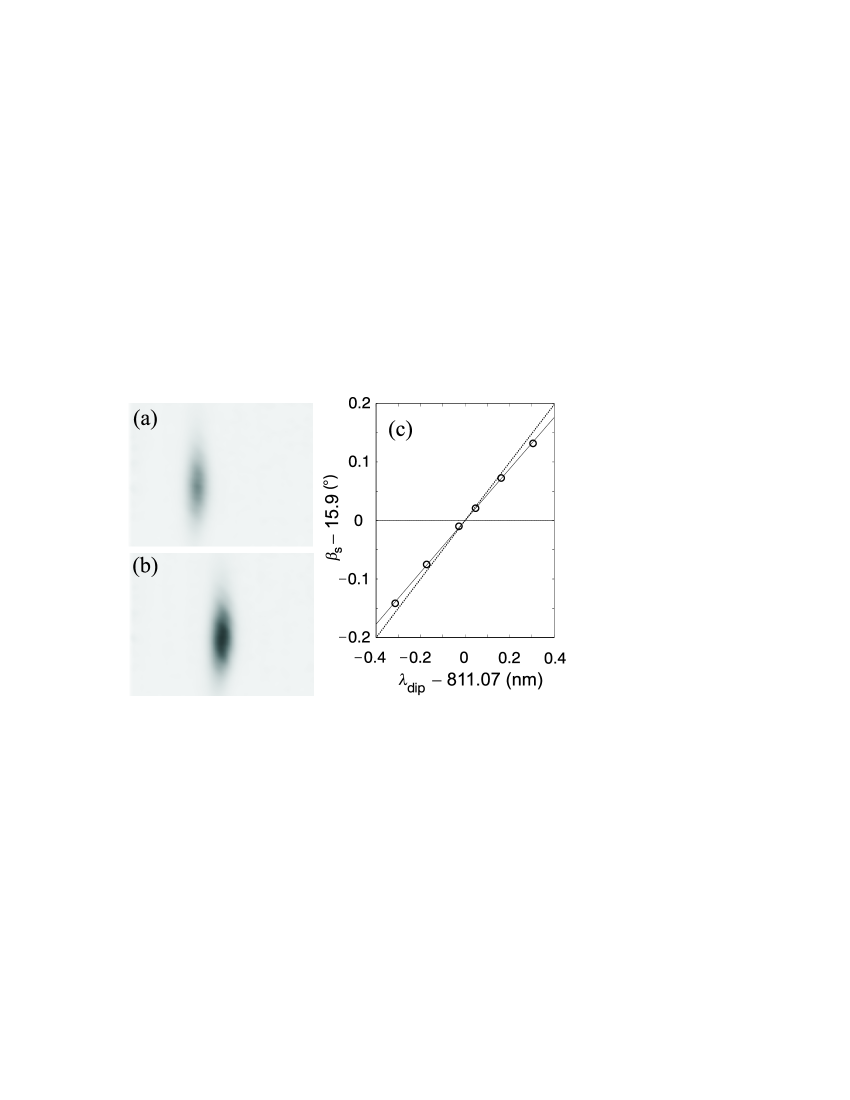
In order to detune the Bragg condition we vary the lattice constant via the wavelength of the lattice laser. For each lattice constant the Bragg-diffracted light is shone onto a CCD camera (see Figs. 4(a),(b)). By fitting a Gaussian curve to a horizontal cut through the image we get the center position of the beam. The pixel size of the camera is . Together with the distance between camera and atomic cloud we determine the relative emission angle of the Bragg-beam for various lattice constants. Figure 4(c) shows that the reflection angle varies with the lattice constant, thus . Furthermore, the reflection angle slightly deviates from equation (2) (dotted line), but follows the generalized Bragg condition (11) (solid line). The findings demonstrate that our system is far from the assumption of infinitely extended layers. By introducing the aspect ratio equation (11) is rewritten as
| (14) |
By fitting the data from figure 4(c) with equation (14) (fitting parameter ) we get an aspect ratio of . This means that the ratio of the width to the length of the lattice . The radial size is approximately m, we therefore calculate a lattice length of mm. This means that about layers take part in the Bragg scattering process, which exceeds our rough guess of the lattice length by 20%. The comparatively narrow radial atomic distribution implies a self-adjustment of the Bragg condition to the lattice constant, i.e. is automatically kept constant. Still, small deviations from this situation (dotted line in Figure 4(c)) are experimentally seen.
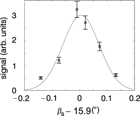
The tolerance for the acceptance angle is equal to the divergence of the outgoing beam . As can be seen from the calculation of the output solid angle (Eq. (9)) . To compare this value with the experimental data, the intensity of the reflected light extracted from figure 4(a),(b) is plotted against the emission angle. These data are then fitted by a Gaussian curve (see Fig. 5). The full width at half maximum of this fit is , which agrees very well with the theoretical value of .
In conclusion, we studied Bragg-reflection at a 1D optical lattice. From a structure factor calculation we deduce a generalized Bragg condition which is valid not only in the solid state physics limit of infinitely spread scattering layers, but also for the case where boundary effects play a role, with the extreme limit of a linear chain of localized scatterers. By comparing the theoretical results with measurements of the emission angle of the Bragg-reflected light we show that our optical lattice is very close to the latter case. This case is characterized by the fact that it is hard to detune the light scattering away from the Bragg condition, because the emission angle self-adjusts to the Bragg condition. This can have undesired consequences for the probing of one-dimensional photonic bandgaps predicted to appear in optical lattices as a consequence of multiple reflections between subsequent layers Deutsch95 ; Coevorden96 . Indeed their signatures are most conveniently probed at a detuned Bragg angle, such that the band edge spectrally lies outside the resonance frequency of the atomic transition. In this way, the region close to the atomic transition, where multiple reflection competes with diffuse light scattering Birkl95 can be avoided. This is not possible, if the lattice is close to being a chain of point scatterers. Ways to overcome this problem include the choice of larger beam diameter for the dipole trap (eventually by confining the atoms in higher-order TEM modes Kruse03 ), smaller Bragg angles and longer lattices.
We acknowledge financial support from the Landesstiftung Baden-Württemberg.
References
- (1) E. O. Wollan, Rev. Mod. Phys. 4, 206 (1932).
- (2) P. S. Jessen and I. H. Deutsch, Adv. At., Mol., Opt. Phys. 37, 95 (1996).
- (3) G. Birkl, M. Gatzke, I. H. Deutsch, S. L. Rolston, and W. D. Phillips, Phys. Rev. Lett. 75, 2823 (1995).
- (4) M. Weidemüller, A. Hemmerich, A. Görlitz, T. Esslinger, and Th. W. Hänsch, Phys. Rev. Lett. 75, 4583 (1995).
- (5) S. Slama et al., Phys. Rev. Lett. 94, 193901 (2005).
- (6) M. Ben Dahan, E. Peik, J. Reichel, Y. Castin, and C. Salomon, Phys. Rev. Lett. 76, 4508(1996).
- (7) M. Greiner et al., Nature 415, 39 (2002).
- (8) B. Paredes et al., Nature 429, 277 (2004).
- (9) C. Fort et al., Phys. Rev. Lett. 90, 140405 (2003).
- (10) D. Kruse et al., Phys. Rev. A 67, 051802(R) (2003).
- (11) B. Nagorny et al., Phys. Rev. A 67, 031401(R) (2003).
- (12) J.M. Coley: Diffraction Physics, North-Holland Personal Library (1995).
- (13) I. H. Deutsch, R. J. C. Spreeuw, S. L. Rolston, and W. D. Phillips, Phys. Rev. A 52, 1394 (1995).
- (14) D. V. van Coevorden, R. Sprik, A. Tip, and A. Lagendijk, Phys. Rev. Lett. 77, 2412 (1996).