European Laboratory for Non-Linear Spectroscopy (LENS), via Nello Carrara 1, I-50019 Sesto Fiorentino (FI), Italy.
Dipartimento di Fisica, Università di Catania, via S. Sofia 64, I-95124 Catania, Italy.
Effects of atomic coherence on propagation, absorption, and amplification of light; electromagnetically induced transparency and absorption Wave propagation, transmission and absorption Coherent spectroscopy of atoms and molecules
Slow Light amplification in a non-inverted gain medium
Abstract
We investigate the propagation of a coherent probe light pulse through a three-level atomic medium (in the –configuration) in the presence of a pump laser under the conditions for gain without inversion. When the carrier frequency of the probe pulse and the pump laser are in a Raman configuration, we show that it is possible to amplify a slow propagating pulse. We also analyze the regime in which the probe pulse is slightly detuned from resonance where we observe anomalous light propagation.
pacs:
42.50.Gypacs:
42.25.Bspacs:
82.53.KpThe intriguing physics of atomic three–level systems, for the first time observed in Pisa in 1976 by the group of A. Gozzini [1], is at the basis of all the recent experiments on slow light propagation [2] and speculations about possible realizations of quantum memories [3], quantum phase gates [4] and photon–counters with unprecedented efficiency [5, 6]. Many other phenomena involving three-level systems have attracted much interest; among them the possibility of observing amplification without inversion (AWI) [7] and anomalous propagation [8, 9]. Anomalous propagation but in an inverted two–level system has already been studied by the group of R. Chiao [10] and more recently in a three–level configuration with Raman scheme by the group of Dogariu [11]. On the other hand subluminal propagation inside the gain band of a xenon discharge has been observed early in the seventies [12].
In this letter we extend the treatment of [8] to the case of a pumped –configuration under the conditions for gain without inversion. This offers the possibility to observe gain while at the same time reducing the propagation speed of a pulse. Furthermore, it is possible to reduce absorption in the anomalous propagation regime. Indeed, in the latter regime, even though the pulse center of mass is advanced with respect to a pulse propagating in vacuum, the pulse edge never goes faster than the speed of light in vacuum, unless population inversion is present. In order to observe gain without inversion it is necessary to populate both the ground states of the system without populating the excited state. We show how this can be achieved starting from the thermal population (equal population in the ground states and no population in the excited state) by introducing suitable incoherent pumping rates in the ground states.
We start by considering a pulse, Gaussian in form, propagating through an atomic medium of optical thickness which is much smaller than the incident pulse length [8]. The level scheme we analyze is represented in figure 1 and consists of two ground sub–levels and and an excited level . A strong laser field (pump) with Rabi frequency and a weak laser field (probe) with Rabi frequency connect to the excited level the ground sub–levels and respectively. The excited state can decay to the ground states and with rates and respectively. Only ground state decays to levels outside those considered here with rate .
[width=.4]CarusoFig1.eps
As in [8] we analyze propagation using the lowest order expansion in the probe intensity of the complex refractive index around the carrier frequency . This approximation is fully justified in the regime considered, as it will be evident in the following discussion. We are interested in the group velocity , its dispersion and the probe transmission intensity . In the above expansion these quantities are represented by:
| (1) |
| (2) |
| (3) |
where is the real part of the refractive index , is the length of the atomic medium and the speed of light in vacuum. We have defined a group velocity dispersion function that has the dimension of a reciprocal velocity.
We use a density matrix treatment and expand in powers of the probe Rabi frequency. For weak probe intensities the complex steady-state atomic susceptibility exhibited to the probe can be fully accounted for by the first order expansion,
| (4) | |||||
where is the scaled sample average density , is the probe resonant wavelength and is the normalized population of level . The overall dephasings and of levels and are expressed in terms of the respective levels linewidths (see fig. 1). In equation (4) we also neglect contributions due to the atomic velocity distribution, since these can be eliminated by choosing a co–propagating pump and probe laser configuration.
In obtaining equation (4) we have assumed that the populations of the levels do not vary much with time. This assumption is justified since the Rabi frequency of the pump laser is smaller than the excited state linewidth (), and the probe laser is taken to be much weaker than the pump. Furthermore, because the excited state may decay to other atomic levels outside the two considered here, in all the following we will assume . In order to check the validity of these assumption we have solved the full system of optical Bloch equations for an open three level system including the possibility to pump population in any of the three levels and the possibility for the population to decay to levels outside those considered here from any of the three levels. The usual situation corresponds to the case where decay from the ground levels is negligible with respect to decay from the excited state. However, in such a case the steady state population ratio of the two ground levels is fixed by the Rabi frequencies of the lasers. Instead we consider the more realistic situation of a room temperature cell in which atomic populations are thermally distributed among all levels. Therefore the initial configuration would be a nearly 50/50 distribution between the two ground states; in addition we have introduced a loss mechanism from the level while for level we have considered the correct branching ratios for 87Rb. In figure 2 we show how the steady state population ratio between the two ground levels, even in presence of the laser beams, can indeed be varied this way while, at the same time, the amount of population placed in the excited level remains negligible. We note that a similar loss from the ground state can be easily implemented by an incoherent RF field stimulating a transition to any other ground sub–level. However this configuration has the disadvantage that while the population in level increases so does the dephasing rate of the ground states superposition. This strongly affects both the gain and the propagation of the pulse as discussed below.
[width=.5]CarusoFig2.eps
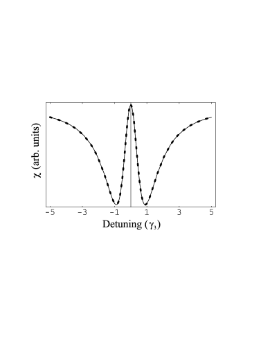
We can now check that the steady state atomic susceptibility computed from equation (4) is the same as the one computed from the full solution of the density matrix for the parameters considered here. This is shown in figure 3 left for a pump Rabi frequency of and of the atomic population in level . This corresponds to the situation where .
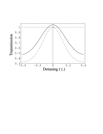
We denote by the probe detuning while the pump beam is taken to be exactly at resonance (). From equations (4) and (3) we obtain the transmission spectrum around the atomic resonance of the probe laser through a 10 cm long cell containing 87Rb at a temperature of C. This is reported in figure 3 right for a pump Rabi frequency of . The transmission shows a peak in correspondence to the probe resonance, i.e. when the pump and probe lasers close a Raman transition between levels and . This is precisely the electromagnetically induced transparency (EIT) in which the probe absorption at resonance is canceled by destructive quantum interference between the two possible absorption paths for the probe laser, namely the two–step transition from to level through the excited level and the Raman two–photon transition between levels and [13, 7]. The peak in the spectrum goes all the way to full transmission when all the atomic population is placed in level (dashed line). On the contrary, when some population ( in figure 3 right) is present in level the transmission goes above unity indicating the presence of gain (continuous line). We should remark that, as shown in figure 2, no population inversion is present in the system therefore we are fulfilling the condition for gain without inversion [7]. In the situation considered here increasing the population of level does not necessarily lead to extracting more gain. Indeed since we are changing the population ratio by incoherently removing population from level , which in turn increases the dephasing rate between the ground sublevels. When the dephasing increases the EIT effect is reduced and no gain is observed. In figure 4 we report the centerline gain as a function of the dephasing rate with all the other experimental parameters fixed as in figure 3. As expected the gain increases to a maximum and then drops down to zero.
[width=.4]CarusoFig4.eps
Combining equations (1) e (2) with equation (4), we obtain the frequency dependence of the group velocity and its dispersion around the probe resonance for the same experimental parameters as before as reported in figure 5. We note that there are three probe frequencies where the group velocity dispersion vanishes. These points correspond to frequency values where a suitable probe pulse can propagate through the medium without distortion. One of these points corresponds to the line center where we have retarded propagation. The other two, which are symmetrical with respect to the first point, correspond to anomalous propagation, i.e. a negative group velocity. We note that, when some population is placed in level , the positive minimum of the group velocity is increased. This is not an effect of population but of the increase in dephasing of the ground sub–levels. At the same time the negative minimum group velocity is also increased. This means that, under the conditions of gain without inversion, a propagating pulse will be slowed down while, at the same time, undergoing amplification whereas in the anomalous propagation region the pulse is advanced but not amplified. However both the pulse delay and the pulse advance are reduced with respect to normal EIT.
[width=.5]CarusoFig5.eps
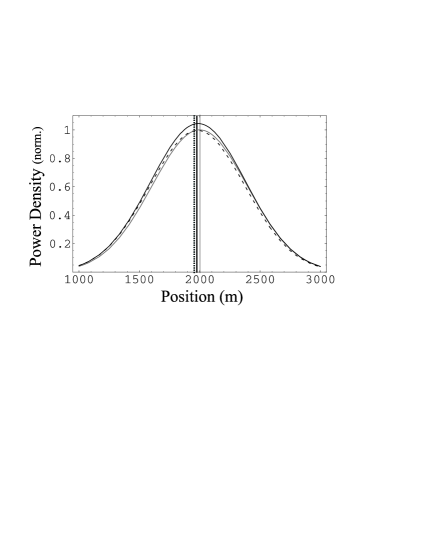
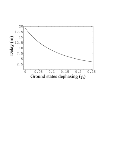
In figure 6, we report the power density spectrum for a Gaussian probe pulse propagating through a 10 cm long cell again for a pump Rabi frequency of . On the left we show the resonant case where the pulse propagation is retarded. We have chosen the parameters to be at the maximum amplification (black line), in such a case the delay with respect to a pulse propagating in vacuum (grey line) is 12.2 m which amounts to a velocity of in the cell. In the normal EIT situation (dotted line) with all the population in level and virtually no dephasing between the ground sublevels this delay is 18.9 m. As already mentioned, when we increase the decay rate from level , there is a reduction of the delay as a consequence of the larger dephasing between the ground levels. As reported in figure 7 (left) for our experimental parameters the delay is reduced below 5 m when the dephasing is equal to 0.25 . As reported in figure 4 at the same level of dephasing no amplification is observable.
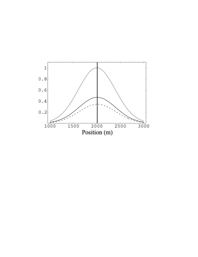
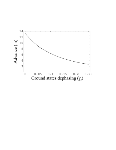
Conversely the detuned case, shown in figure 6 right, exhibits a pulse advanced of 13.3 m with respect to the one propagating in vacuum, but the advanced propagation is accompanied by absorption. The absorption is reduced when some population is placed in level but, at the same time, also the advance is reduced to 8.6 m. We note that the observed delay and advance can be greatly enhanced by reducing the pump Rabi frequency but the effect of the levels population balance on the pulse advance is strongly suppressed. In the anomalous propagation regime, the pulse advance is decreased with respect to the normal EIT in a such way that the pulse edge never appears ahead of the edge of a pulse propagating in vacuum for the same distance. This effect is enhanced by the larger dephasing rate as shown in figure 7 (right) and the advance is below 3 m when the dephasing rate reaches 0.25 . We note that in the regime of population inversion the amplified pulse leading edge can indeed precede that of the vacuum propagating pulse. This is not surprising since, by inverting the atomic levels population, we are effectively storing energy in the medium [14].
In conclusion we have shown that in the presence of gain without inversion it is possible to observe effects similar to those of pure EIT, i.e. retarded propagation in absence of absorption for the resonant case and anomalous propagation accompanied by absorption in the detuned case. However in presence of gain without inversion a propagating pulse is less retarded than in the pure EIT case, while at the same time undergoing amplification. On the other hand in the anomalous propagation region the pulse absorption is reduced and the advance is also reduced in such a way that the pulse edge never precedes that of a pulse propagating in vacuum. We have performed all the calculations for a sample of a 87Rb vapor at C in a 10 cm long cell. We have examined a realistic model to create the atomic population ratios needed for AWI introducing an incoherent loss rate from one of the ground levels. We have discussed how this mechanism affects the dephasing rates of the ground levels. This model is easily extendable to the case of weak coherent fields to study decoherence in quantum memories as well as to discuss AWI in connection with photon cloning.
Acknowledgements.
We thank M. Inguscio and E. Rimini for most valuable discussions and their continuous support of this work. We are deeply indebted to M. Artoni and G. La Rocca for their many useful suggestions.References
- [1] \NameAlzetta G., Gozzini A., Moi L., Orriols G. \REVIEWNuovo Cimento36B19765.
- [2] \NameHau L.V., Harris S.E., Dutton Z., Behroozi C. \REVIEWNature3971999594, \NameLiu C., Dutton Z., Behroozi C.H., Hau L.V. \REVIEWNature409 2001490, \NamePhillips D., Fleischhauer A., Mair A., Walsworth R., Lukin M. D. \REVIEWPhys. Rev. Lett.862001783.
- [3] \NameFleischhauer M. Lukin M. D. \REVIEWPhys. Rev. A652002022314.
- [4] \NameOttaviani C., Vitali D., Artoni M., Cataliotti F. Tombesi P. \REVIEWPhys. Rev. Lett.902003197902.
- [5] \NameImamoglu A. \REVIEWPhys. Rev. Lett.892002163602.
- [6] \NameLukin, M. \REVIEWRev. Mod. Phys.752003457
- [7] \NameArimondo E. \BookProgress in Optics \EditorWolf E. \PublElsevier Science, Amsterdam \Year1996 \Page257
- [8] \NameArtoni M., La Rocca G.C., Cataliotti F.S. Bassani F. \REVIEWPhys. Rev. A632001023805.
- [9] \NameGodone A., Levi F. Micalizio S. \REVIEWPhys. Rev. A662002043804.
- [10] \NameBolda E. L., Garrison J. C., and Chiao R. Y. \REVIEWPhys. Rev. A4919942938.
- [11] \NameWang L. J., Kuzmich A., Dogariu A. \REVIEWNature4062000277, \NameWang L. J., Kuzmich A., Dogariu A. \REVIEWNature4112001974.
- [12] \NameCasperson L., Yariv A. \REVIEWPhys. Rev. Lett.261971293.
- [13] \NamePavone F.S., Artoni M., Bianchini G., Cancio P., Cataliotti F.S. Inguscio M. \REVIEWEuropean Physical Journal D1199885.
- [14] \NameArtoni M., Loudon R. \REVIEWPhys. Rev. A571998622