Experimental Quantum Key Distribution with Decoy States
Abstract
To increase dramatically the distance and the secure key generation rate of quantum key distribution (QKD), the idea of quantum decoys—signals of different intensities—has recently been proposed. Here, we present the first experimental implementation of decoy state QKD. By making simple modifications to a commercial quantum key distribution system, we show that a secure key generation rate of 165bit/s, which is 1/4 of the theoretical limit, can be obtained over 15km of a Telecom fiber. We also show that with the same experimental parameters, not even a single bit of secure key can be extracted with a non-decoy-state protocol. Compared to building single photon sources, decoy state QKD is a much simpler method for increasing the distance and key generation rate of unconditionally secure QKD.
Quantum key distribution (QKD) BB84 ; ekert1991 was proposed as a method of achieving perfectly secure communications. Any eavesdropping attempt by a third party will necessarily introduce an abnormally high quantum bit error rate in a quantum transmission and thus be caught by the users. With a perfect single photon source, QKD provides proven unconditional security guaranteed by the fundamental laws of quantum physics securityproof ; moresecurityproof .
Most current experimental QKD set-ups are based on attenuated laser pulses which occasionally give out multi-photons. Therefore, any security proofs must take into account the possibility of subtle eavesdropping attacks, including the PNS (photon number splitting) attack PNS . A hallmark of those subtle attacks is that they introduce a photon-number dependent attenuation to the signal.
Fortunately, it is still possible to obtain unconditionally secure QKD, even with (phase randomized) attenuated laser pulses, as theoretically demonstrated by ilm and Gottesman-Lo-Lütkenhaus-Preskill (GLLP) GLLP . However, one must pay a steep price by placing severe limits on the distance and the key generation rate. See also OtherPracticalSecurity .
A key question is this: how can one extend the distance and key generation rate of secure QKD? A brute force solution to this problem would be to use a (nearly) perfect single photon source. Despite much experimental effort singlephoton , reliable perfect single photon sources are far from practical.
Another solution to increase the transmission distance and key generation rate is to employ decoy states, using extra states of different average photon number to detect photon-number dependent attenuation. It has attracted great recent interests. The decoy method was first discovered by Hwang hwang2003 . In decoy , we presented the first rigorous security proof of decoy state QKD. We showed that the decoy state method can be combined with standard GLLP result to achieve dramatically higher key generation rates and distances. Moreover, we proposed practical protocols with vacua or weak coherent states as decoys. Subsequently, the security of practical protocols have been analyzed by Wang wang and us practical . See also harrington2005 . In particular, we practical demonstrated theoretically the clear practicality of decoy state QKD using only one decoy state. We call such a protocol a one-decoy protocol.
However, until now, all decoy state QKD papers hwang2003 ; decoy ; wang ; practical ; harrington2005 have been theoretical and there has been no experimental demonstration. Here, we present, for the first time, an experimental realization of decoy state QKD.
We remark that additional errors will appear in experimental implementation of a decoy state protocol. An example of a source of additional errors is intensity modulation, which, as will be discussed below, is required for the implementation of decoy state QKD. Those additional errors will change the parameters and, thus, the quantitative results in the simulations done in previous papers decoy ; practical ; wang . Therefore, to quantify the advantage of decoy state QKD in practice, it is crucial to perform a real experiment and analyze the data obtained experimentally.
In our experiment, we use acousto-optic modulators (AOM) to achieve polarization insensitive modulation, which is important for our set-up. While already used in telecommunications, we believe that this is the first time that AOMs have been introduced in a QKD experiment. In summary, our experiment demonstrates a new approach—decoy state QKD—with a new experimental component—AOM—in QKD.
We will first discuss the GLLP result and how the decoy state method can be combined with GLLP to achieve high key generation rate and distance. The GLLP GLLP method can be used to prove the security of QKD based on a phase randomized weak coherent state source. With the GLLP method the secure key generation rate, which is defined as the ratio of the length of the secure key to the total number of signals sent by Alice, is given by decoy
| (1) |
where depends on the protocol q , the subscript is the average photon number per signal in signal states, is the gain gain of signal states, is the quantum bit error rate (QBER) of signal states, is the gain of the single photon states (i.e., the probability that Alice generates exactly a single photon which is finally detected by Bob) in signal states, is the error rate of single photon states in signal states. is the bi-directional error correction rate brassard1994 , and is the binary entropy function: . and can both be measured directly from experiments, while and have to be estimated (because we could not measure the photon number of each pulse).
Owing to the loss in a fiber, its length determines the gains and QBERs (as denoted by ) and therefore, the key generation rate . At the distance where the key generation rate hits zero, the QKD protocol is no longer secure (with the standard classical post-processing protocol which uses only one-way classical communications).
Clearly, to estimate key generation rate, the main task is to estimate a lower bound of and an upper bound of . However, in non-decoy state approaches, the estimations are quite poor. This is the reason why, with non-decoy state approaches, QKD can be proven to be secure only at very limited key generation rate and distance. While experimental QKD has been demonstrated at 122km in telecom fibers GYS , most of the previous experiments do not appear to satisfy the strict security analysis demanded in non-decoy approaches GLLP ; insecurity . Given that security is the most crucial issue in QKD, this is a highly unsatisfactory situation.
Fortunately, decoy state QKD comes to the rescue. As discussed below, decoy state QKD allows dramatic improvement in our estimations of and , compared to non-decoy approaches. The basic idea of decoy state QKD is as follows: in addition to the signal state with average photon number , one introduces some “decoy” states with some other average photon numbers and blends signal states with decoy states randomly on Alice’s side signals . For instance, in a one-decoy state protocol practical , the average photon number of a decoy state is much lower than that of the signal state. After Bob’s acknowledgement of receipt of signals, Alice broadcasts which pulses are signal states and which are decoy states. Alice and Bob can, therefore, analyze the statistical characteristics (i.e., transmittance and QBER) of each type of signal separately. Since one assumes all characteristics (except photon number distribution) of the signal state and the decoy state are the same, Eve’s eavesdropping attack can depend on the actual photon number in each pulse, but she has no knowledge which state (signal or decoy) the pulse is in. Eve’s attack will modify the characteristics (transmittance or QBER) of decoy states and/or signal states and will be caught. For instance, in a one-decoy state protocol, if Eve introduces a photon-number dependent attenuation to the channel, then the transmittance of the decoy state (which has a much lower average photon number than the signal state) will generally be much lower than what Alice and Bob would expect under normal operations. Note that decoy states are used only for catching an eavesdropper, but not for key generation. It has been shown decoy ; wang ; practical that, in theory, decoy state QKD can substantially enhance security and performance of QKD.
Before describing our experiment, we would like to point out that if one already had a uni-directional QKD system GYS ; uniQKD in place, the implementation of decoy state QKD would have been much easier: one can simply drive the laser source directly to various power levels.
Modified “Plug and Play” set-up: Unfortunately, most existing commercial QKD systems are bi-directional (“Plug & Play”) in the sense that Bob sends out a chain of strong signals to Alice, who attenuates each signal to single photon level and modulates (i.e., encodes quantum information on) it before sending it back to Bob, who performs the measurement (i.e., decoding of quantum information), after which a new chain of strong signals will be sent to Alice. Therefore, the intensity modulation by Alice has to be carefully synchronized with Bob’s laser source.
Here, we show that, even with such a commercial system (manufactured by id Quantique in our current set-up), one can successfully implement decoy state QKD by making simple modifications.
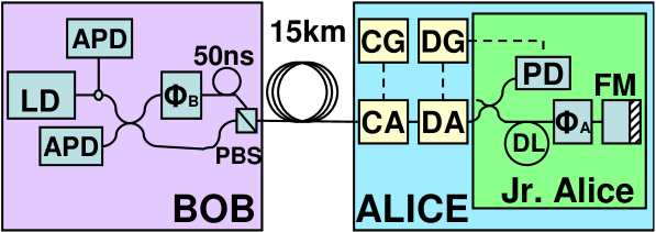
Our Experiment: FIG. 1 illustrates the schematic of our system. The commercial QKD system consists of Bob and Jr. Alice. In our experiment, Alice consists of Jr. Alice and four new optical and electric components: an AOM (DA in FIG. 1), a function generator (DG in FIG. 1), a compensating AOM (CA in FIG. 1) and a compensating generator (CG in FIG. 1). Their functions will be discussed below.
We implement the one decoy state protocol proposed by our group in practical on top of the standard BB84 BB84 protocol. In a one decoy state protocol, Alice must randomly modulate the intensity of each signal to either signal state level or decoy state level before sending it back to Bob. We add an AOM (DA in FIG. 1) on Alice’s side. A function generator (DG in FIG. 1) controls the transmittance of the AOM.
A critical issue in our set-up is to compensate the phase shift due to our AOM. Since the Mach-Zehnder Interferometer (MZI) on Bob’s side is asymmetric, the frequency shift introduced by AOM causes a significant phase shift between the two pulses that go through different arms of MZI. To compensate this phase shift, another AOM, the “Compensating AOM” (CA in FIG. 1) is employed to make the total phase shift multiples of . This AOM is driven by the second function generator, “Compensating Generator” (CG in FIG. 1) CACG .
Optimization of Parameters: We perform a numerical simulation practical with parameters of our set-up ExpPara and optimally set and to 0.80 and 0.12 photons respectively. The actual distribution of the states is produced by an id Quantique Quantum Random Number Generator. Around 10% of the signals are assigned as decoy states, which is optimal according to numerical simulation practical . This random pattern is generated and loaded to the Decoy Generator before the experiment decoyprofile .
Except for the modulation period, the transmittance of Decoy AOM (DA) is set to maximum. As the classical detector (PD in FIG. 1) inside Alice detects the first pulse from Bob, it triggers the Decoy Generator (DG). The Decoy Generator (DG) will then hold a delay time before outputting the random pattern to modulate different states. The Compensating AOM (CA) is used only for the purpose of phase compensation. Thus, its transmittance is set to be constant.
Recall that each signal in a “Plug and Play” set up consists of two time-separated pulses. To keep visibility high, the two pulses of the same signal must be attenuated equally, which means the delay time must be very precise. In our experiment, the delay time was determined with an accuracy of 10ns.
In our experiment, a total of M raw bits (including both signal states and decoy states) were sent using quantum key distribution from Alice to Bob. The transmitting time was less than four minutes.
After the transmission of all the signals, Bob announced which signals had actually been received by him and in which basis. Alice broadcasted to Bob the distribution of decoy states as well as basis information. We assume Alice and Bob announced the measurement outcomes of all decoy states as well as a subset of the signal states. From those experimental data, Alice and Bob then determined , , and , whose values are now listed in Table 1.
| Para. | Value | Para. | Value | Para. | Value |
|---|---|---|---|---|---|
| 0.4478 | |||||
| brassard1994 | 1.22 |
Analysis of Experimental Results: Alice and Bob have to derive a lower bound on the key generation rate, , by applying the theory of one decoy state protocol to their experimental data. To begin, we discuss the theory of one decoy state protocol. The one-decoy state protocol was first proposed in decoy and analyzed in practical . In such a protocol, only one decoy state is used (in principle, more decoy states might increase key generation rate) whose average photon number is . The transmittance/gain of the decoy state and its error rate could also be acquired directly from experiments. Taking statistical fluctuations into account, the lower bound of , and the upper bound of are given by practical
| (2) | ||||
in which
| (3) |
where is the number of pulses used as decoy states fluctuation , and (=1/2) is the error rate for the vacuum signal and therefore the lower bound of key generation rate is
| (4) |
In our analysis of experimental data, we estimated and very conservatively as within 10 standard deviations (i.e., =10), which promises a confidence interval for statistical fluctuations of .
The experimental results listed in Table 1 are the inputs for Eqs. (2-4), whose output is a lower bound of the key generation rate, as shown in Table 2. Even with our very conservative estimation of and , we got a lower bound for the key generation rate per pulse, or 165bits/s, which means a final key length of about kbit. We also calculated , the theoretical limit from the case of infinite data size and infinite decoy states protocol, by using Eq. (1). We remark that our lower bound is indeed good because it is roughly of . This fact suggests that it is not necessary, or rather, not economical to use either a very large quantity of data or a lot of different decoy states.
| Para. | Value | Para. | Value |
|---|---|---|---|
Based on the method described in GLLP ; decoy ; practical , we carefully performed numerical simulations with ExpPara . We found that without decoy method, no matter what value of we choose or how large the data size we use, the key generation rate, , will hit zero at only 9.6km. In other words, at 15km, not even a single bit could be shared between Alice and Bob with guaranteed security. In contrast, our numerical simulations show that, with decoy states, our QKD set-up can be made secure over 50km, which is substantially larger than the secure distance (9.6km) without decoy states.
In summary, we have performed the first experimental demonstration of decoy state QKD, over 15km of Telecom fibers. Our experiment shows that, with rather simple modifications (by adding commercial acousto-optic modulators, AOM) to a commercial QKD system, decoy method allows us to achieve much better performance with substantially higher key generation rate and longer distance than is otherwise possible. We conclude that, with careful conceptual design and optimization, decoy state QKD is easy to implement in experiments. It is, therefore, ready for immediate commercial applications.
We thank enlightening discussions with colleagues including C. H. Bennett, D. Bethune, G. Brassard, F. Dupuis, J. Harrington, H. J. Kimble, L. LeBlanc, D. W. C. Leung, N. Lütkenhaus, L. McKinney, J. Preskill, C. Rose, K. Tamaki, X.-B. Wang and Z. Yuan. We particularly thank G. Ribordy for his generous help in our experiment. Financial support from Connaught, NSERC, CRC Program, CFI, id Quantique, OIT, PREA, CIPI, and the University of Toronto is gratefully acknowledged. H.-K. Lo also thanks travel support from the IQI at Caltech through the NSF under grant EIA-0086038.
References
- (1) C. H. Bennett, G.Brassard, Proceedings of IEEE International Conference on Computers, Systems, and Signal Processing, (IEEE, 1984), pp. 175-179.
- (2) A. K. Ekert, Phys. Rev. Lett. 67 661 (1991)
- (3) D. Mayers, J. of ACM 48, 351 (2001); H.-K. Lo, H. F. Chau, Science, 283, 2050 (1999); E. Biham et al. Proceedings of the Thirty-Second Annual ACM Symposium on Theory of Computing (STOC’00) (ACM Press, New York, 2000), pp. 715-724; P. W. Shor, J. Preskill, Phys. Rev. Lett. 85, 441, (2000)
- (4) K. Ekert, and B. Huttner, J. of Modern Optics 41, 2455 (1994); D. Deutsch et al., Phys. Rev. Lett. 77, 2818 (1996); Erratum: Phys. Rev. Lett. 80, 2022 (1998).
- (5) Eve can selectively surpress all the single photon signals from Alice, and split all the multi photon signals, keeping one copy herself and send the other copy to Bob. In this way, Eve could have an identical copy of what Bob processes, thus breaking the security of BB84 protocol. Although such attacks may appear to be beyond current technology, the first rule in cryptography is: never underestimate the determination and ingenuity of your opponents in breaking your codes.
- (6) H. Inamori, N. Lütkenhaus, D. Mayers, in press (available at http://arxiv.org/abs/quant-ph/0107017)
- (7) D. Gottesman et al. Quantum Information and Computation 4, 325 (2004)
- (8) M. Koashi, available at http://arxiv.org/abs/quant-ph/0403131 ; V. Sacarani et al. Phys. Rev. Lett. 92 057901, K. Inoue et al. Phys. Rev. A 71 042305, M. Curty et al. Phys. Rev. A 69 042321
- (9) J. McKeever, et al. Science 303, 1992 (2004); Z. L. Yuan, et al, Science 295, 102 (2002); M. Keller et al. Nature 431, 1075 (2004)
- (10) W.-Y. Hwang, Phys. Rev. Lett. 91, 057901 (2003)
- (11) H.-K. Lo, in Proceedings of IEEE ISIT 2004, p. 137; H.-K. Lo, X. Ma, K. Chen, Phys. Rev. Lett. 94 230504 (2005).
- (12) X. -B. Wang, Phys. Rev. Lett. 94 230503 (2005); X. -B. Wang, Phys. Rev. A 72 012322 (2005)
- (13) X. Ma et al. Phys. Rev. A 72 012326 (2005)
- (14) J. W. Harrington et al. in press (available at http://arxiv.org/abs/quant-ph/0503002)
- (15) Our experimental implementation is based on BB84 protocol. In the cases that Alice and Bob use the same basis, pulses are used as signal states. Factor in Eq. (1) is thus given by .
- (16) The gain is defined to be the ratio of the number of receiver Bob’s detection events to the number of signals emitted by sender Alice in the cases where Alice and Bob use the same basis.
- (17) G. Brassard, L. Salvail, Advances in Cryptology EUROCRYPT ’93, Vol. 765 of Lecture Notes in Computer Science, (Springer, Berlin, 1994), pp. 410-423.
- (18) C. Gobby, Z. L. Yuan, A. J. Shields, Appl. Phys. Lett. 84 3762 (2004)
- (19) Many existing QKD experiments take an ad hoc value of 0.1 for the average photon number of the signal. Besides, few of them have considered the most general eavesdropping attack allowed by quantum mechanics.
- (20) Here, we assume that the source emits coherent states and the phases of all states (signals or decoys) are randomized. Therefore, the photon number of the signal state follows a Poissonian distribution with a parameter whereas that of a decoy state follows a Poissonian distribution with a parameter .
- (21) The same strategy fails miserably for a bi-directional QKD system because Eve can easily monitor the intensity of the ancillary strong signal originated from Bob.
- (22) Given a variable frequency driver for DA (which is also commercially viable), CA and CG could be taken off.
- (23) Laser nm at 5MHz, background rate , fiber loss 0.21dB/km, Bob’s quantum efficiency =0.0227, detector error rate .
- (24) In principle, for perfect security, a new random pattern should be chosen for each frame. For ease of implementation, in our experiment, the same pattern was reused for every frame. Note, however, that each signal within a frame was still modulated individually.
- (25) This is because in our experiment, the yield for the cases that Alice and Bob use the same basis is the same as that for the cases that they use different basis.