Graph State Preparation and Cluster Computation with Global Addressing of Optical Lattices
Abstract
We present a novel way to manipulate ultra-cold atoms where four atomic levels are trapped by appropriately tuned optical lattices. When employed to perform quantum computation via global control, this unique structure dramatically reduces the number of steps involved in the control procedures, either for the standard, network, model, or for one-way quantum computation. The use of a far-blue detuned lattice and a magnetically insensitive computational basis makes the scheme robust against decoherence. The present scheme is a promising candidate for experimental implementation of quantum computation and for graph state preparation in one, two or three spatial dimensions.
The trapping and control of atoms within an optical lattice is currently a topic of intense theoretical and experimental research, with a view to simulating many-body systems Jaksch et al. (1998); Kuklov and Svistunov (2003) and implementing quantum computation Jaksch et al. (1999); Brennen et al. (1999); Pachos and Knight (2003). While high fidelity initialisation of suitable states has been experimentally demonstrated Mandel et al. (2003); Peil et al. (2003), there are still significant barriers to a full scale implementation. Primarily, the apparent requirement for individual addressing of atoms is a major obstacle. To overcome this, a number of techniques are employed, such as increasing the separation between lattice sites Scheunemann et al. (2000); Peil et al. (2003), or using magnetic gradients Khudaveryan et al. (2004). Global control Benjamin (2002); Benjamin et al. (2003) is a conceptually different approach that localises the action of global pulses to a specific site of the lattice. Previous proposals require either long initialisation times Vollbrecht et al. (2004) or employ superlattices Calarco et al. (2004); Kay and Pachos (2004). Another problem appearing in present implementations is that two–qubit gates require the transportation of entangled qubits around the lattice. This results in heating that reduces the fidelity of the gate. The concept of a one–way computation Raussendorf and Briegel (2001); Raussendorf et al. (2003) has been proposed to resolve this problem. This involves performing appropriate measurements on any of a special class of many-body entangled states, known as graph states. The simplest example of such states, from the perspective of experimental creation in optical lattices, is that of the cluster state Mandel et al. (2003).
In this letter, we present a realistic proposal for one–way quantum computation in an optical lattice where the addressability problem is resolved by global addressing. A significant reduction in the complexity of the control sequences, and the principal novelty of the scheme, is brought about by the appropriate tuning of optical lattices. A far-off resonant lattice is used to trap four different atomic states , , and . A suitably tuned lattice can be added to move and without perturbing and . We could have chosen to use these states to realise qudits ( or ), and perform computation directly with them. Instead, we keep the states and in reserve to act as a unique, mobile, qubit which we refer to as the pointer. This allows us to construct very simple control procedures that implement one– and two–qubit gates, measurements on individual qubits and create general graph states. The simplicity of the scheme allows us to employ more than one dimension to perform the computation, thus significantly reducing the overall time needed to transport information through the lattice. Independent control of the pointer position (with interferometric precision) facilitates the implementation of both one and two qubit gates without the need to ramp the magnetic field in the vicinity of a Feshbach resonance Calarco et al. (2004).
The computation is initialised by forming an optical lattice (labelled ) with one atom in state trapped in each lattice site Greiner et al. (2002); Mandel et al. (2003). To initialise the pointer, we need to convert one of the atoms (or just add an extra one) into the state. As an alternative to the techniques described in Vollbrecht et al. (2004); Kay and Pachos (2004), we could transfer an atom from the edge of the lattice to the state and move it into the computational region. To perform the transportation, we need an additional, state selective, lattice, with a wavelength which is chosen such that the states and are not perturbed. Subsequently, the pointer is manipulated independently from atoms in the computational basis by . The relative position of and is adjusted with very high precision using interferometric techniques. We can move the pointer around and cause it to interact with any single qubit as we desire. The interaction between the pointer and the target qubit results in phase accumulation that is conditional on the presence of the pointer. In conjunction with Raman transitions applied to the entire device, this interaction is sufficient to generate all the control procedures we require.
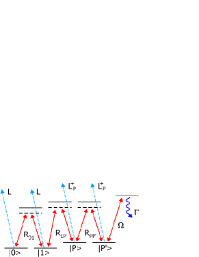
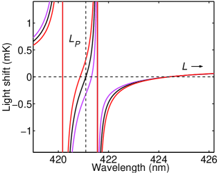
To create the effective level scheme seen in Figure 1, we trap alkali atoms (such as 87Rb) in an optical lattice, , of wavelength which is detuned by a few hundred nanometers from the main atomic resonance. The logical basis of our qubits is encoded in the magnetically insensitive hyperfine sublevels of the ground state of the atom. For 87Rb, we select and . The use of such states greatly reduces the sensitivity of the computation to external fields. For the pointer qubit, we select two of the magnetically sensitive states (with the same magnetic quantum number). In the far-detuned lattice, , all the hyperfine ground states see the same trapping potential (see Fig. 2). In order to move the pointer , we introduce an additional lattice, . This is composed of a static circularly polarised component, , that exactly cancels and an orthogonally polarised component, , whose phase controls the position of the pointer. By tuning the frequency of within the fine structure splitting of the excited state, one can arrange that it does not perturb the qubit states. When using Rb, for example, we would select a wavelength of 421.1 nm, for the transition (see Fig. 2). In addition to the lattices and , we will allow application of Raman transitions , between the states and , to the whole lattice.
The central mechanism in our scheme requires an interaction between the single pointer state, , and a particular, target, qubit. Specifically, we are interested in creating a phase gate on the target qubit, conditional on the presence of the pointer. There are two different physical mechanisms that could be used, depending on how the collisional energy shifts between the pointer and atoms in states and compare ( and respectively). In both cases, we move the pointer to the same lattice site as the target qubit (by switching on and adjusting the phase of ), induce the interaction, and then move the pointer away again. If , we can create a phase difference () simply by waiting for an appropriate time. The additional global phase of is irrelevant. Naturally, this gate takes longer as the difference in energy decreases. However, the difference between and can be made large by working with an ambient magnetic field in the vicinity of an appropriate interspecies Feshbach resonance.
Alternatively, we can induce the interaction independently of the values of and by driving a stimulated Raman transition, , between the state and a molecular bound state Calarco et al. (2004); Wynar et al. (2000). This is similar to inducing a Feshbach resonance but, by using light, the speed of this operation is only limited by the Rabi frequency of the free-to-bound transition, which can be much higher than the collisional shift. A pulse flips the sign of the component only at the target site, where the resonant molecular bound state exists, thus giving the required phase difference. In this scenario, the collisional couplings ( and ) are ‘always-on’, and a differential effective interaction, , is induced by light.
Both techniques have the common property that they allow the application of a phase gate to a single qubit by addressing the entire structure (i.e. a localised phase gate). We will now demonstrate how to combine this with Raman transitions, again applied to the whole structure, to create all the elements required for universal quantum computation.
The one–qubit gate, , () can be implemented on a target qubit in a straightforward way. The rotations and are performed using the Raman transition on all the qubits. The pointer is used to create a localised operation, as has already been described.
The simplest way to perform a measurement on a specific qubit is to employ the fourth state, . Since this state is also transported by , care has to be taken over the order of operations. Firstly, the pointer should be moved to the same lattice site as the target qubit, then selective promotion of the target from to is achieved by performing a Hadamard in the basis; a phase gate conditional on the presence of the pointer; and a second Hadamard. A global measurement of the state can then be performed, providing information only about the state of the target qubit. If found in this state, the qubit must be reset to the state. Finally, the pointer is moved away.
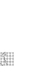
A two–qubit gate also employs similar control procedures to those of the one–qubit gate. In particular, we perform a Hadamard gate using , which therefore only acts on the pointer. Suitable generation of phases by collision with the control qubit, and repetition of the Hadamard with , causes selective deactivation of the pointer (by placing it in ), dependent on the state of the control qubit. The pointer qubit can then be moved to the target qubit to perform a one–qubit gate (as seen in Fig. 3), before undoing the initial, entangling, steps. As a result, a general controlled-unitary can be realised.
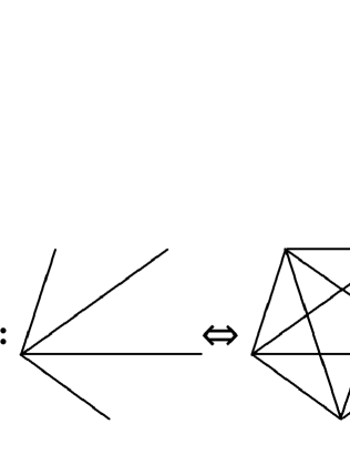
This method for creating a two–qubit gate allows for a particularly efficient generalisation to multi-qubit gates where there is a single control and multiple targets. All that is required is to perform the entangling steps 1-5 in Fig. 3 once, then repeat steps 6 and 7 for each target, before performing steps 5-1 to remove the pointer from the entangled state. A particularly simple example is to create graph states of the form between arbitrary qubits on the lattice. As seen in Fig. 4, this is achieved by performing a global Hadamard, , controlled phase gates on of the qubits (all controlled by the qubit) and then another global . Finally, a local must be performed on the qubit. At this stage the pointer is disentangled and can be used to perform measurements on the state. An arbitrary graph state can be prepared by applying this procedure an appropriate number of times. In particular, we can take advantage of the equivalence of the entanglement properties of graphs under local unitaries (Fig. 4) in order to minimise the number of edges, each of which represents a controlled phase interaction Hein et al. (1995).

In order to perform a one-way quantum computation, we do not need to perform any two–qubit gates. Instead, entanglement is used as an initial resource by preparing the system in a cluster state. Here we can use to perform a Hadamard, then to promote the components to so that they can be transported, enabling collisions between neighbouring qubits. This involves shifting the lattice independently by a single lattice site in the -and -directions and creating a phase of both times. Finally, we must reset the states to .
This completes the control set that is required, namely the ability to perform single qubit rotations and measurements along with either two–qubit gates or initialisation of a cluster state. All these controls are simply built upon the ability to rotate the phase of one of the trapping lattices in order to shift its minima, and to perform Raman transitions and measurements on the whole lattice. The great advantage in employing cluster states for computation stems from the fact that the pointer, the one absolutely critical component in a global control scenario, is never disturbed from its state . It is not necessary to carry an entangled qubit around the lattice, and thus the risk of decoherence is dramatically reduced. Nevertheless, it is worth quantifying the additional resources required. Consider, for example, performing a single qubit rotation in a one–way computation. This is achieved by performing single qubit rotations and measurements on 5 qubits (the single qubit rotations are necessary because we have a fixed measurement basis). Similarly, in order to perform a two–qubit gate between distant qubits, the pointer has to be moved between the two. In the case of a standard computation, the (entangled) pointer is moved over approximately rows if the two qubits to be entangled are separated by qubits on the circuit diagram (assuming computation in 2D). In the case of the cluster computation, we have to move the pointer over approximately rows and columns, making single qubit rotations and measurements Raussendorf et al. (2003).
The threshold for fault-tolerant quantum computing places a stringent demand on minimising decoherence. For optical lattices, far-blue detuning Davidson et al. (1995) of the trapping light represents the most viable option: in this case atoms are trapped at the minima of the light field, and decoherence due to spontaneous scattering is reduced by an additional factor of order , where is the harmonic oscillator length of the trap ground state. For example, when considering Rb with a trap frequency of 1 MHz, the spontaneous scattering rate for a lattice wavelength between 428 and 590 nm is much less than , and can be neglected compared to other sources of decoherence.
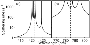
It is also necessary to ensure that the techniques employed to implement computations do not introduce intolerable levels of scattering. For example, while moving the pointer, the qubit states are exposed to, on average, half the intensity of . Fig. 5 shows the scattering rate for a fixed trap frequency of 1 MHz in the vicinity of the and resonances of Rb. The scattering rate is more than an order of magnitude smaller for the weaker resonance. For this reason we choose the transition to manipulate the pointer atom. The average scattering rate for our four states, due to the state-selective lattice (at 421.1 nm) with a trap frequency of 1 MHz, is less than , so the probability of spontaneous emission during a move time of 1 s is less than 10-4. If we relax the trap frequency by a factor of 10, we decrease the computation speed by 10, but the spontaneous emission rate is also reduced by the same factor, so the spontaneous emission rate per gate operation is unchanged. Consequently, the optimum trap frequency is a trade-off between decoherence due to spontaneous emission and other mechanisms such as the excitation of motional states. In our scheme, we reduce the sensitivity to motional decoherence by keeping the computational qubits stationary throughout.
In Benjamin et al. (2003), it was indicated that performing constant measurements on some sections of a globally controlled device can result in error suppression. The underlying mechanism is based on the Zeno effect, which can help to stabilise classical states Kay and Pachos (2004). Unless we are performing a two–qubit gate we can safely measure the state, forbidding transitions that might accidentally cause this state to become populated. Such error suppression will minimise the need for increasingly complex schemes such as error correction.
In summary, we have proposed a system that allows the trapping and manipulation of four atomic levels using two appropriately tuned optical lattices. This structure enables the implementation of a variety of quantum computation schemes, including a one–way computation, that are based on global addressing, as well as the preparation of graph states between arbitrary qubits. The simplicity of the control procedures as well as significant suppression of some decoherence mechanisms render the present scheme as a plausible candidate for experimental realisation of quantum computation in optical lattices.
Acknowledgements J.K.P. would like to thank Hans Briegel for inspiring conversations and C.S.A. wishes to thank Simon Cornish for stimulating discussions. This work was partially supported by EPSRC and the Royal Society.
References
- Jaksch et al. (1998) D. Jaksch et al., Phys. Rev. Lett. 81, 3108 (1998).
- Kuklov and Svistunov (2003) A. Kuklov and B. Svistunov, Phys. Rev. Lett. 90, 100401 (2003).
- Jaksch et al. (1999) D. Jaksch et al., Phys. Rev. Lett. 82, 1975 (1999).
- Brennen et al. (1999) G. Brennen, C. Caves, P. Jessen, and I. Deutsch, Phys. Rev. Lett. 82, 1060 (1999).
- Pachos and Knight (2003) J. K. Pachos and P. L. Knight, Phys. Rev. Lett. 91, 107902 (2003).
- Mandel et al. (2003) O. Mandel et al., Nature 425, 937 (2003).
- Peil et al. (2003) S. Peil et al., Phys. Rev. A 67, 051603 (2003).
- Scheunemann et al. (2000) R. Scheunemann, F. S. Cataliotti, T. W. Hänsch, and M. Weitz, Phys. Rev. A 62, 051801 (2000).
- Khudaveryan et al. (2004) M. Khudaveryan et al. (2004), quant-ph/0411120.
- Benjamin (2002) S. C. Benjamin, Phys. Rev. Lett. 88, 017904 (2002).
- Benjamin et al. (2003) S. C. Benjamin, A. Bririd, and A. Kay (2003), quant-ph/0308113.
- Vollbrecht et al. (2004) K. Vollbrecht, E. Solano, and J. I. Cirac, Phys. Rev. Lett. 93, 220502 (2004).
- Calarco et al. (2004) T. Calarco et al., Phys. Rev. A 70, 012306 (2004).
- Kay and Pachos (2004) A. Kay and J. K. Pachos, NJP 6, 126 (2004).
- Raussendorf and Briegel (2001) R. Raussendorf and H. Briegel, Phys. Rev. Lett. 86, 5188 (2001).
- Raussendorf et al. (2003) R. Raussendorf, D. E. Browne, and H. J. Briegel, Phys. Rev. A 68, 022312 (2003).
- Greiner et al. (2002) M. Greiner et al., Nature 415, 39 (2002).
- Wynar et al. (2000) R. Wynar et al., Science 287, 1016 (2000).
- Hein et al. (1995) M. Hein, J. Eisert, and H. J. Briegel, Phys. Rev. A 69, 062311 (1995).
- Davidson et al. (1995) N. Davidson et al., Phys. Rev. Lett. 74, 1311 (1995).