Moiré patterns in quantum images
Abstract
We observed moiré fringes in spatial quantum correlations between twin photons generated by parametric down-conversion. Spatially periodic structures were nonlocally superposed giving rise to beat frequencies typical of moiré patterns. This result brings interesting perspectives regarding metrological applications of such a quantum optical setup.
pacs:
42.50.Ar; 42.50.St; 42.50.LcSpatial quantum correlations in light beams has attracted a great deal of interest lately. A number of recent works devoted to this subject constitute a whole new area often called Quantum Images misha . Among the optical systems capable of experimentally producing space-time correlations, parametric amplifiers and oscillators are the most frequently employed. The striking quantum nature of the correlations created by such devices combined with their simplicity make them specially attractive. In cavity free parametric down-conversion, the conditional images are observed in the photocount regime, where the spatial correlations can be interpreted as a consequence of transverse momentum entanglement in the quantum state of the twin photons. This entanglement has been used in a variety of experiments monken ; padua and more recently combined with polarization entanglement to produce polarization controlled quantum images juliana .
The studies of quantum images in the high photon flux regime are complementary to the single photon case. In such high flux regimes, correlations in spatially dependent photocurrents are measured rather than photocounts. We may also quote very interesting results in this case, including the recent experimental demonstration of sub-shot noise measurement of small displacements with a spatially squeezed light beam treps . The potential applications of such correlations has also motivated spatial noise measurements in semiconductor lasers lasers .
While some experimental progress has been achieved in the quantum domain, a wide knowledge base of classical imaging is already available. An attractive challenge is to match the progress in both domains to obtain new technologies and new applications of the quantum optical setups. In this work we present a contribution involving the observation of moiré patterns in quantum images. When structures with periodic or quasi-periodic layouts are superposed, new structures appear as a consequence of the beat between the spatial frequencies in the spectra of the original layouts. These are the well known moiré fringes moire . This effect plays an important role in many different fields like solid structures analysis or optical metrology, for example.
When solid structures are studied through X-ray diffraction or Transmission Electron Microscopy (TEM), the superposition of slightly different structures gives rise to moiré fringes. Since the spatial beat frequencies are much smaller than those belonging to the spectra of the original structures, the moiré effect provides a considerable sensitivity enhancement to small structural imperfections xray ; tem . The moiré effect has also a number of applications to optical metrology. From surface analysis of thin films diagnostics to strain structure measurements in human teeth odonto , the moiré effect has been employed as a powerful tool for high sensitivity measurement of the spatial structure of surfaces. An interesting technique called Projection Moiré Interferometry consists of projecting the image of a primary periodic structure on a secondary one to obtain the moiré pattern. If the spatial frequency of the primary structure is previously known, then the one of the secondary structure can be readily obtained through the measurement of the moiré beat frequency. This method provides an excellent accuracy and has already been used for noncontact temperature measurements on Si with a resolution of si . In summary, the moiré technique provides high sensitivity to small deformations in a periodic or quasi-periodic structure. This property has been recently applied to an image encryption scheme criptografia , where the intensity function corresponding to the image to be encrypted is used to deform a periodic structure. The encrypted image is then recovered through the moiré pattern between the deformed structure and a reference pattern.
In our experiments, we used the spatial correlations between twin photons produced by spontaneous parametric down conversion to observe moiré patterns in quantum images. We exploited two important features: the image transfer from the pump beam to the spatial profile of the quantum correlations, and the combined transmission through masks remotely placed in the signal and idler beams. Therefore, two experimental setups were employed. In the first setup, one transmission grating was placed in the pump beam while the other one was placed in the down-converted idler beam. In the second setup, the transmission gratings were placed in the down-converted signal and idler beams.
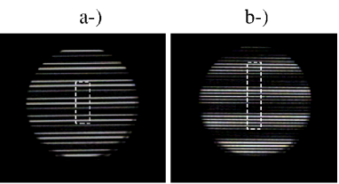
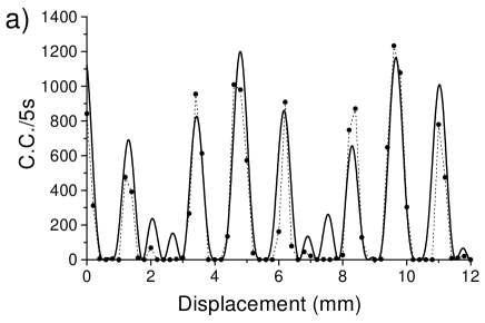
For each setup, two different regimes were investigated. In the first regime, the spatial periods of the gratings were quite different (1.2 and 1.6 mm), so that both the high and the low spatial frequencies were visible in the superposition of the gratings. In the second regime, two gratings with similar spatial periods were used (0.8 and 0.9 mm). In this case, only the slow beat frequency could be clearly followed. The standard moiré patterns obtained with the two pairs of gratings are presented in Fig. 1. They were registered with a CCD camera. In Figs. 1.a and 1.b we show the moiré patterns created by the first and the second pair of gratings respectively. While in the first case a complicated structure appears, in the second one the low frequency modulation can be easily identified. The dashed lines in both figures outline the regions scanned in the quantum optical setups.
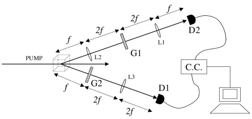
The first setup used is shown in Fig. 2. A 5 mm long LiIO3 crystal was pumped by 425 nm wavelength pulses obtained from a frequency doubled Ti-Saf laser. Pairs of quantum correlated signal and idler beams were generated through type I parametric down-conversion at wavelengths 890 nm (signal) and 810 nm (idler), and detected with photo-avalanche detectors (D1 and D2). A pinhole with 0.5 mm diameter was placed in front of each detector. The coincidence count was performed electronically and registered with a computer.
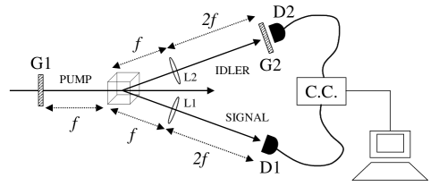
The first grating (G1) was placed in the pump beam before the nonlinear crystal. It is well known that the spatial correlations between the signal and idler beams propagate like the pump profile after the crystal, except for a wavelength dependent scaling factor monken . The image of G1, carried by the signal-idler correlations, was projected on the detection plane by two identical lenses (L1 and L2) with focal length , inserted in the down-converted beams. The second grating (G2) was then placed right before D2. Under such conditions, the spatial profile of the coincidence count is expected to be proportional to the product G1 G2 juliana2 . Since down-conversion was nearly degenerate, the scaling factor for image transfer was close to 2. Therefore, gratings with half the desired spatial period were introduced in the pump beam in order to produce spatial correlations with the desired effective modulations.
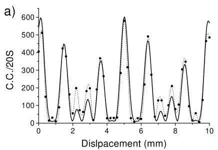
The coincidence region was quite narrow, which means that, for a given position of the signal (idler) detector, coincidences could be observed when the idler (signal) detector was scanned over a narrow region about 4 mm in area. So, it was impossible to measure the quantum image by scanning the detectors. Instead, we fixed the detectors and scanned both gratings at the same time. In Fig. 3a we show the coincidence profile as a function of the gratings position. This profile corresponds to the moiré pattern shown in Fig. 1a. A grating with 0.8 mm period (G1) was introduced in the pump beam and displaced in steps of 0.1 mm, thus producing an effective 1.6 mm period modulation on the correlations, scanned in effective steps of 0.2 mm. The second grating (G2), with a 1.2 mm period, was introduced right before the idler detector and scanned in steps of 0.2 mm in the same sense as G1. For such parameters, the expected slow moiré modulation period is 4.8 mm, in very good agreement with the spacing between the large peaks in Fig.3a. The solid line in this figure is the product of two cosine squared functions with the periods of G1 and G2, showing a very good agreement for both the fast and the slow modulation. The small deviations of the experimental data from the solid line are probably due to distortions of the real gratings with respect to ideal cosine functions and to the finite size of the detectors aperture, which limits the spatial resolution.
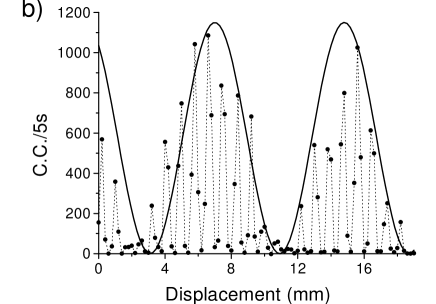
The coincidence profile in Fig. 3b corresponds to the moiré pattern shown in Fig. 1b. This time, a 0.4 mm period grating (G1) was introduced in the pump beam, producing an effective modulation with 0.8 mm period in the coincidence profile. The other grating (G2) had a 0.9 mm period, therefore very close to that of G1. This time G1 was scanned in steps of 0.0 5mm, so producing an effective scan in steps of 0.1 mm, and G2 was scanned in steps of 0.1 mm. The high frequency modulation arising from the superposition was too fast, so that a meaningful fit could be provided only for the slow beat modulation. The solid line is a single cosine squared envelope with a slow beat period of 7.8 mm, which is quite close to the expected value of 7.2 mm.
In a second setup, we used a different strategy to demonstrate the appearance of moiré patterns in quantum images. The spatial profile of the quantum correlations between the twin photons carries the combined effect of the transmission through two obstacles remotely placed in each photon path padua . It is useful to interpret this effect in an advanced wave picture, where one of the twin photon detectors represents an ideal point like source, whose emission is “reflected”at the crystal surface and detected on the other detector klyshko . Based on this picture we developed the experimental setup shown in Fig. 4. The idler detector (D2) is regarded as a point like source. A collimating lens (L1) is introduced at a distance equal to the focal length from the “source”. The first grating (G1) is placed at a distance from L1. The signal beam optics follows the advanced wave reasoning, so that a second lens (L2), identical to L1, projects the image of G1 over the second grating (G2). All distances are chosen in order to preserve the original size of G1 in the projection. Finally, the image of the superposed gratings is projected by a third lens (L3, identical to L1 and L2) at the signal detection plane, so that the product G1 G2 is produced in this case as well. As in the first setup, we scanned the gratings rather than the detectors, since the coincidence region was quite narrow in this case as well.
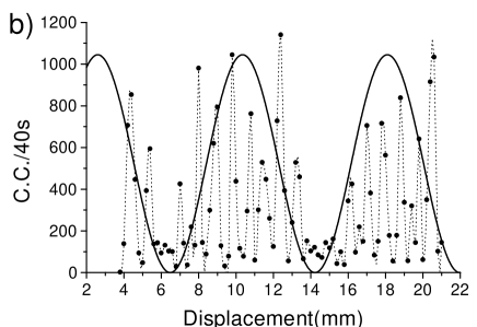
The experimental results obtained with the second setup are shown in Fig. 5. In Fig. 5a, we used the same gratings as in Fig. 1a. The slow modulation at a 4.8 mm period is again very clear. The solid line is the product of two cosine squared functions and is in very good agreement with the experimental data. In Fig. 5b we used the same gratings as in Fig. 1b. The slow modulation at 7.8 mm period is also very clear. The solid line is a single cosine squared function with this slow period.
In conclusion, we performed the first demonstration of moiré patterns in quantum images. Two strategies were employed, the first one being the transfer of images and angular spectrum from the pump beam to the spatial quantum correlations between the twin photons. The second strategy made use of an advanced wave picture to produce the moiré patterns with two similar gratings, remotely placed in the signal and idler beams. Our results may motivate interesting applications to noncontact measurements of small mechanical deformations. The moiré patterns appear in a variety of different fields, where these results could be of great interest.
Acknowledgements.
The authors thank P.A.M. dos Santos for fruitful discussions. This work is supported by the Conselho Nacional de Desenvolvimento Científico e Tecnológico (CNPq) through the Instituto do Milênio de Informação Quântica and Programa de Núcleos de Excelência (PRONEX). The PRONEX project is also supported by the Fundação de Amparo à Pesquisa do Estado do Rio de Janeiro (FAPERJ). The authors aknowledge partial funding from Coordenação de Aperfeiçoamento de Pessoal de Nível Superior (CAPES/PROCAD and CAPES/COFECUB projects).References
-
(1)
Corresponding author. E-mail address: khoury@if.uff.br
- (2) M. I. Kolobov, Rev. of Mod. Phys. 71 (5), 1539-1589 (1999).
- (3) C.H. Monken, P.H. Souto Ribeiro, S. Pádua, Phys. Rev. A 57 (4), 3123 (1998); W. A. T. Nogueira, S. P. Walborn, S. Pádua, and C. H. Monken; Phys. Rev. Lett. 86, 4009 (2001).
- (4) E.J.S. Fonseca, P.H. Souto Ribeiro, S. Pádua, C. H. Monken, Phys. Rev. A 60, 1530 (1999).
- (5) D.P Caetano, P.H. Souto Ribeiro, J.T.C. Pardal, and A.Z. Khoury; Physical Review A 68, art. no 023805 (2003).
- (6) N. Treps, U. Andersen, B. Buchler, P. K. Lam, A. Maitre, H. A. Bachor, C. Fabre, Phys. Rev. Lett. 88 (20), Art. No. 203601 (2002); N. Treps, A. Maitre, C. Fabre, U. Andersen, B. Buchler, P. K. Lam, H. A. Bachor, Journal de Physique IV 12 (PR5), 153-154 (2002); N. Treps, N. Grosse, W. P. Bowen, C. Fabre, H. A. Bachor, P. K. Lam, Science 301 (5635), 940-943 (2003).
- (7) A. Bramati, J. P. Hermier, A. Z. Khoury, E. Giacobino, P. Schnitzer, R. Michalzik, K. J. Ebeling, J. P. Poizat, P. Grangier, Optics Letters, 24 (13), 893-895 (1999); J. P. Hermier, A. Bramati, A. Z. Khoury, E. Giacobino, J. P. Poizat, T. J. Chang, P. Grangier, J. Opt. Soc. of Am B 16 (11), 2140-2146 (1999); C. L. G. Alzar, S. M. de Paula, M. Martinelli, R. J. Horowicz, A. Z. Khoury, G. A. Barbosa, J. Opt. Soc. of Am B 18 (8), 1189-1195 (2001).
- (8) K. Patorski, Handbook of the Moiré Fringe Technique, (Elsevier, Amsterdam, 1993); I. Amidror and R.D. Hersch; J. Opt. Soc Am. A15, 1100 (1998); J. A. O. Huguenin, B. Coutinho dos Santos, P. A. M. dos Santos, and A. Z. Khoury, J. Opt. Soc. Am. A 20, 1883-1889 (2003).
- (9) P. A. Bezirganyan, V. P. Asfanyan, Kristallografiya 29 (5), 882-887 (1984); T. Ahilea T, E. Zolotoyabko, J. Hartwig, M. Ohler, E. Prieur, J. Appl. Phys. 84 (11), 6076-6082 (1998); M. Ohler and J. Härtwig Acta Cryst. A 55, 413-422 (1999).
- (10) A. Madhukar, Q. Xie, P. Chen, and A. Konkar, Appl. Phys. Lett. 64 (20), 2727-2729 (1994); J. M. Zuo, B. Q. Li, Phys. Rev. Lett. 85 (25), Art. No 255502 (2002).
- (11) Irving P. Herman, Optical diagnostics for thin film processing, Academic Press, New York (1996).
- (12) R. Z. Wang and S. Weiner, Journal of Biomechanics, 31 (2), 135-141 (1997).
- (13) S. H. Zaidi, S. R. J. Brueck, Mc. Neil Jr., J. of Vac. Science & Technology B, 10 (1), 166-169 (1992); M. K. Lang, G. W. Donohoe, S. H. Zaidi, S. R. J. Brueck, Opt. Engineering 33 (10), 3465-3471 (1994).
- (14) J. Apolinar Muñoz-Rodríguez and Ramón Rodríguez-Vera, Opt. Comm. 236, 295-301 (2004).
- (15) P. H. Souto Ribeiro, D. P. Caetano , C. H. Monken, J. T. C. Pardal, A. Z. Khoury; J. of Mod. Opt. 51 (6-7), 983-990 (2004).
- (16) T. B. Pittman, D. V. Strekalov, D. N. Klyshko, M. H. Rubin, A. V. Sergienko, Y. H. Shih, Phys. Rev. A 53, 2804 (1996);