Quantum computer with dipole-dipole interacting two-level systems
Abstract
A scalable, high-performance quantum processor can be implemented using near-resonant dipole-dipole interacting dopants in a solid state host. In this scheme, the qubits are represented by ground and subradiant states of effective dimers formed by pairs of closely spaced two-level systems, while the two-qubit entanglement either relies on the coherent excitation exchange between the dimers or is mediated by external laser fields.
pacs:
03.67.Lx, 42.50.FxI Introduction
Quantum information science, which is based on quantum principles and which extends and generalizes the classical information theory, is currently attracting enormous interest, due to its fundamental nature and its potentially revolutionary applications to computation and secure communication QCQI . Quantum information processing schemes rely on the ability to coherently manipulate and couple (or entangle) the qubits—quantum analogs of classical bits. The main stumbling blocks en route to the realization of useful quantum computers, comprised of many qubits, are: (i) fidelity loss due to decoherence, which grows with the amount of single- and two-qubit operations and requires large redundancy for the application of error-correction methods errCorr ; ECnnch ; (ii) scalability of the quantum processor, which restricts the choice of candidate systems. Although the various proposals and experimental demonstrations of rudimentary quantum computers have thus far predominantly involved optical manipulations of atoms in ion traps iontr , high-Q cavities PGCZ ; MBBKNSK , optical lattices BCJD and microtraps JCZ ; CZnat ; SDKMRM , the low fidelity and/or difficulties with scalability of these schemes cast doubts on their suitability for truly large-scale quantum computation. Solid-state quantum processors with quantum dots qdots ; IABDVLShS ; BLW or active dopants dopsSC ; BDHT ; LH appear to be more promising, both principally and technologically.
In a recent publication PKprl we have proposed a combined optical/solid-state approach that can significantly improve the speed, fidelity and scalability of a quantum processor. The crux of this approach is the concept of dimer qubit, wherein two similar two-level systems (e.g., quantum dots), separated by a few nanometers and interacting with each other via the resonant dipole-dipole interaction (RDDI) Lehmberg ; Agarwal-MQE ; GKABR , form an effective dimer, whose ground and subradiant Dicke states serve as robust qubit states. It is the purpose of this paper to give a complete account of that scheme and compare it with other related systems proposed for physical realization of quantum computation. We will show that all the basic ingredients of quantum computation DiVincenzo , i.e., state preparation, universal logic gates and qubit readout, are realizable by optical manipulations of these dimers. A scalable quantum processor is envisioned in a cryogenically-cooled solid-state host material doped with such dimers at controllable nanoscale separations.
The paper is organized as follows. In Sec. II we review the resonant dipole-dipole interaction between two two-level systems (atoms), which build our dimer qubit. We then discuss the laser-dimer interaction and outline the mechanism by which the qubits are manipulated and measured. In Sec. III we study the dipole-dipole interaction between pairs of closely spaced dimers, which mediates their entanglement. Finally, in Sec. IV we describe the implementation of the scalable quantum processor, followed by the concluding remarks.
II The Qubit
In this section we will introduce the notion of “dimer qubit” and outline the principles of its manipulation and measurement.
II.1 Resonant dipole-dipole interaction
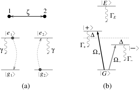
Let us first recall the cooperative properties of two identical two-level atoms (TLAs), 1 and 2, at fixed positions and , whose ground and excited states are labeled as and , respectively [Fig. 1(a)]. The atoms interact with each other via the continuum of free-space modes of electromagnetic field. Using the standard Born-Markov approximation to eliminate the vacuum modes of the photonic continuum Lehmberg ; Agarwal-MQE , one can derive an effective non-Hermitian Hamiltonian for the system of two TLAs, which can be cast in a form
| (1) |
Here the first term
| (2) |
represents the atomic Hamiltonian, where is the resonant frequency and the radiative decay rate on the atomic transition . The second term
| (3) |
with
| (4) | |||||
| (5) | |||||
describes the resonant dipole-dipole interaction (RDDI) between the atoms, where is the angle between the direction of atomic dipole moment and the interatomic axis, and , with and , is the normalized distance between the atoms. Thus, the rate of coherent excitation exchange between the atoms is given by the real part of the RDDI potential , while the imaginary part of the potential is responsible for the cooperative radiative decay of the system. When , both and vanish and so does the , and we essentially deal with the system of two independent atoms described by the Hamiltonian .
In the opposite limit of small interatomic separations , the natural basis of sates for the two-atom system is the molecular basis. The transformation form the atomic to molecular basis is achieved via the diagonalization of the Hamiltonian (1). This yields the dressed by the RDDI “dimer” eigenstates
| (6) |
with the corresponding eigenvalues
as shown in Fig. 1(b). Thus the symmetric (superradiant) and doubly-excited eigenstates have corresponding decay rates and which exceed that of a single isolated atom, while the decay rate of the antisymmetric (subradiant) eigenstate is suppressed Dicke . For very small interatomic separations and , the real part of the RDDI potential and decay rates of the corresponding dimer states can be approximated as , , and .
II.2 Dimer-laser interaction
Let us irradiate the pair of atoms with a laser field having frequency , wave vector k, and phase (). The Hamiltonian (1) for the system of two atoms acquires now an atom-field interaction term
| (7) |
where is the Rabi frequency of the field for a single isolated atom, being the dipole matrix element for the atomic transition . Then, in the RDDI-dressed basis (6), the interaction-picture Hamiltonian takes the form
| (8) | |||||
where is the laser field detuning from the transition resonance and
Thus, the Rabi frequencies (coupling strengths) of the laser field on the dimer transitions and are equal to , respectively, and on the transitions and are equal to . In the limit of small interatomic separations, , one has
where is the angle between the vectors k and . Note that identically vanishes if the laser field propagation direction is perpendicular to the interatomic axis, , while, in the case of , it is maximized for the configuration. In physical terms, the subradiant transition exhibits a quadrupolar behavior and dipole-moment suppression, due to destructive interference of the two-atom interactions with the field, as opposed to their constructive interference in the superradiant transition.
Consider first the case of , i.e., the frequency of electric field is resonant with the dimer transition [Fig. 1(b)]. If the initial state of the dimer is either or , the transitions and are nonresonant, as they are detuned by . Then, provided , we can adiabatically eliminate the nonresonant states and , obtaining an effective two-level system described by the Hamiltonian
| (9) | |||||
Here is the relaxation rate of the ground state due to its nonresonant coupling with the superradiant state , while the residual Stark shifts and of levels and , respectively, are absorbed in the laser field detuning, . Assuming that and , i.e., , and therefore neglecting for the moment the relaxation terms in (9), the resulting evolution operator takes the familiar form
which describes the coherent Rabi osculations between levels and with frequency .
Consider now the opposite case , when the frequency of electric field is resonant with the dimer transition [Fig. 1(b)]. For the dimer initially in state , the transition is detuned by . Similarly to the previous case, we can then neglect the nonresonant transitions and , obtaining the effective Hamiltonian
| (10) |
Since the decay rate of the superradiant state is large, , for moderate field amplitudes the coherent Rabi oscillations on the transition will not persist. Rather, the system will very quickly settle to the steady-state, in which the populations of states and are given, respectively, by
II.3 Single-qubit rotations
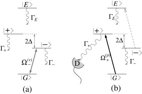
Now we are in a position to introduce the concept of subradiant dimer qubit. The two basis states of the qubit are represented by the dimer ground and subradiant states. An arbitrary single-qubit operation (rotation) can be performed by the laser field with wave vector and frequency that is resonant with the qubit transition [Fig. 2(a)]. As an example, a laser pulse of area (-pulse c_pi-pulse ) would realize the not gate that interchanges the qubit states . Similarly, a pulse with the phase and area (-pulse) would realize, to within the phase-flip of state , the Hadamard transformation.
It is easy to estimate the error per single-qubit rotation operation. During the qubit flip time , the error probability due to the spontaneous emission from the subradiant state has the upper bound , while the error probability due to the population transfer from the ground state to the superradiant state satisfies . Minimizing the total error probability with respect to , we find that, given the values of and , the smallest error per gate operation is attained for , for which . As an example, for the parameters and , the RDDI strength is , the decay rate of the antisymmetric state is , and the error probability during the qubit flip-time is , as compared to the corresponding error probability for a single atom . Such small memory and gate operation errors are amenable to error correction errCorr ; ECnnch .
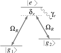
Let us compare the present scheme with another common scheme BCJD ; LH ; PGCZ ; IABDVLShS , where the qubit basis states are represented by two metastable ground states and of an isolated atom (Fig. 3). The single-qubit rotations are performed by two laser fields tuned to the two-photon Raman resonance between the two ground states. In order to minimize the losses, these fields are strongly detuned from the excited state by detuning , where is the spontaneous decay rate of that state. For simplicity, let us assume that the Rabi frequencies of both Raman fields are equal to . Then the effective Rabi frequency on the two-photon transition is given by . Hence, during the qubit flip time , for the error probability due to the decay from the excited state we obtain . With the parameters similar to those for the dimer qubit, and , which yields , we obtain that , which is comparable to the error probability in our scheme. However, the dimer qubit based on the RDDI between TLAs is easier to manipulate since it requires only one laser field.
II.4 Qubit measurement
Next we outline the readout scheme. The method we propose is similar to the electron shelving or quantum jump technique QJumps . In order to measure the state of the qubit, we irradiate it with the probe field having frequency that is resonant with the dimer transition , and collect the fluorescence signal from the superradiant state [Fig. 2(b)]. The Rabi frequency on that transition is , while on the qubit transition , from which the probe field is detuned by , its Rabi frequency is much smaller. Therefore the presence or absence of fluorescence will indicate whether the qubit is in the “bright” state or in the “dark” state . With the qubit in state , the probability of detecting the fluorescence by a detector with finite efficiency during the time the probe field is on, is given by
| (11) |
which, in the case of , can be approximated as . Requiring that , we obtain for the detection time , which, on the other hand, should be much smaller than the lifetime of the qubit state , .
It is imperative to note, however, that the probe frequency exactly matches that of the transition , on which the probe field Rabi frequency is [see Eq. (8)]. Therefore, the dimer in state can first be excited to by absorbing a probe photon, then decay to , subsequently producing the same fluorescence signal as if it were initially in state . One can show that the probability of detecting the fluorescence in that case is described by the equation
| (12) |
which, with , can be approximated as , where is the rate of transition due to the absorption of a probe photon and consequent decay from the state . Requiring that , while still , we obtain the following condition on the system parameters, . With a realistic and (), for the reliability of the measurement we obtain
We finally note that if the propagation direction of the probe field is perpendicular to the interatomic axis, then and the above idle fluorescence does not occur at all during the lifetime of state . As will be seen below, however, such a setup is not very convenient for assembling a quantum processor containing many qubits, which necessitates the above analysis. It is also clear now that if the same probe laser is applied to the qubit for a longer time , it will initialize the state of the qubit to its ground state .
III Entanglement between qubits
Universal quantum computation requires the implementation of arbitrary single-qubit rotations addressed in the previous section and two-qubit logic gates. Here we will discuss two mechanisms for entangling pairs of dimer qubits at well defined locations.
III.1 Swap gate
Consider the RDDI between two dimers and separated by normalized distance satisfying the condition [Fig. 4(a)]. Since during the operation of the quantum computer only the qubit states of the dimers are populated, we can simplify our treatment of the dimer-dimer interaction by considering only the interaction between two two-level systems with the ground and excited states and . Then, from the above analysis we infer that the real part of the RDDI potential between the dimers, responsible for the coherent excitation exchange between state of dimer and state of dimer and vice versa [Fig. 4(b)], can be approximated as .

Let us assume that we have a means to selectively control the frequencies of transitions in both dimers. This can be accomplished, for example, by applying a far off-resonant standing-wave electric field whose node position coincides with the location of dimer . Then at the positions of the two dimers the electric field amplitudes will differ and dimers and will experience different ac Stark shifts [Fig. 4(a)]. If the difference in the qubit transition frequencies of the two neighboring dimers exceeds their coupling strength , the excitation exchange (swap) between them is effectively switched off. To switch the interaction on, one shifts the Stark field profile along the axis until qubit transitions of the two dimers become resonant. Then, during the time , the following transformation takes place,
| (13) |
while other initial states of the two qubits, and , remain unaffected. This is the essence of the swap gate between two qubits.
In the same way, one can realize the square-root of swap () gate between two qubits. By switching on the interaction for time , one can fully entangle the two qubits, attaining an equally weighted superposition of swap and no-swap,
| (14) |
Let us estimate the fidelity of the swap operation. The main source of error in this scheme is the cooperative spontaneous decay of the excited states of the qubits, . With inter-dimer separation , this leads to the swap gate fidelity .
We note that the decoherence-free subspace approach ZB ; Lidar advocates the use of four physical qubits (TLAs) for a single logical qubit represented by two subradiant states of the four-atom system. The universal set of quantum gates relies on the exchange interaction (swap) between pairs of atoms located at a logical qubit (for single-qubit rotation) or at different logical qubits (for two-qubit gate), which can be turned on and off via externally applied electric or magnetic fields. Our dimer qubit approach allows for more efficient use of the system resources (two atoms per qubit), along with simpler and more robust manipulation.
III.2 Fast controlled-phase gate
We now describe an alternative scheme implementing a fast controlled-phase (cphase) logic gate between two qubits [Fig. 5]. Suppose that we irradiate the dimers with a laser field acting on the auxiliary transition , and thereby populating the state . This will induce the RDDI between two closely spaced dimers causing an excitation exchange between state of dimer and state of dimer and vice versa. Using the above analysis, we obtain that the strength of the interaction is given by , which is much larger than , since . Therefore, during a time interval that is small compared to , we can neglect the RDDI between the dimers on the qubit transitions in comparison to that on the auxiliary transitions . To the same accuracy, the eigenstates of the combined system of two dimers are given by
Thus, the singly excited states and , having the decay rates and , correspond, respectively, to the antisymmetric and symmetric combinations of the superradiant and ground states of two dimers [Fig. 5(b)].
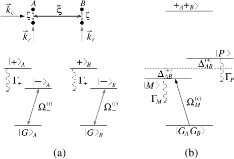
The geometry of the system is depicted in Fig. 5(a), where the interatomic axis of each dimer is perpendicular to the inter-dimer axis, . Each qubit can be separately addressed by the laser field with , as described in Sec. II.3. To perform a two-qubit logic gate, we irradiate the system with the coupling field having wave vector and frequency that is resonant with the transition . The Rabi frequencies of this field on the transitions and are equal, respectively, to and . Since , this field does not couple to the qubit transitions of the dimers. During the time , the system of two dimers, being initially in the state , will undergo one Rabi cycle on the transition and the following transformation will take place,
| (15) |
while all other initial states, such as and , will remain unaffected. This is due to the fact that the RDDI between the dimers is present only if their combined state is either or . Otherwise there is no resonance in the system corresponding to the frequency of the coupling field and, consequently, the field does not interact with the system. Transformation (15) results in a phase shift of the state which corresponds to the cphase logic gate. The comparison of operation times of the swap and cphase gates yields .
We now estimate the fidelity of the cphase gate. The first source of error is the spontaneous emission from state , . Next, an error may occur if the coupling field transfers some population from the ground to the excited state of the system, from where it will decay back to the ground state with random phase, . The last source of error comes about when only one of the qubits is in the ground state and, therefore, the cphase gate is not executed. However, the application of the field to that qubit may result in a small population transfer to the superradiant dimer state . The probability of that process, , turns out to be equal to . Minimizing the total error probability with respect to , we have for . With and , we obtain for the cphase gate fidelity , which is similar to that of the swap gate. However, for the chosen parameters, the cphase gate is 15 times faster than the swap gate.
We note finally that a related scheme implementing the cphase logic gate between two closely spaced Raman qubits (Fig. 3) have been proposed in BCJD . In that scheme, one applies to the pair of atoms and , trapped in an optical lattice, a “catalysis” field having frequency that is near-resonant with the atomic transition . The detuning of that field is smaller than the splitting of the ground states and but larger than the RDDI strength between the atoms on the transitions . Therefore the RDDI is induced only if both atoms are in state . During the interaction with the catalysis field, different initial states of the system, , , and , experience the corresponding ac Stark shifts , and . Thus, to perform the cphase gate, one applies the catalysis field for time . However, the single-atom phase-sifts , accumulated during the gate operation, should be removed through appropriate pulses acting on individual atoms before and after they are made to interact. The probability of error due to the spontaneous emission from the excited states is given by . With , which here has a meaning of the Lamb-Dicke parameter, the error probability is slightly larger than in our scheme. More dramatically, however, for similar field strength and , we find that our implementation of the cphase gate, in addition to being simpler, is times faster.
IV Implementation of quantum processor
Having established all the basic physical principles of operation of the proposed quantum processor, we now describe its possible realization. The processor is composed of a solid-state host doped with active atoms. These atoms should have a non-degenerate ground state, since otherwise the coupling between atoms via vacuum modes of the continuum can mix various degeneracy states GKABR , which would invalidate the simple two-level atomic model we have explored in this paper. Among the possible dopants, pairs of semiconductor quantum dots, often referred to as artificial atoms optQDs , with controllable separations of few nanometers BHHFKWSF , appear to be the best choice for our scheme, due to their large dipole moments and tailorable optical properties.
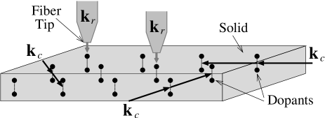
In Fig. 6 we show the scheme of the proposed quantum processor with RDDI dopants in solid state host. There, the qubits are represented by the ground and subradiant states of the dimers formed by pairs of closely spaced atoms. Individual qubits are addressed by laser fields with frequency and wave vector parallel to the interatomic axis, , using the near-field technique. The polarization of the field can be chosen such that it acts only on the atomic transition from the nondegenerate ground state to one of the sublevels of the excited state. This further justifies the validity of the two-level description of the atoms.
Throughout this paper we assumed that the relaxation of the excited atomic state is conditioned merely by the radiative decay. This assumption has resulted in a strong suppression of decoherence on the qubit transition due to the subradiant nature of the antisymmetric state of the dimer. For this to be valid, during the operation of the quantum processor all the competing nonradiative decay processes must be strongly suppressed. This can be accomplished by working below the liquid helium temperatures, at which the density of crystal phonons is negligible phonons , and/or using fast ac Stark modulation of the vibrationally relaxing levels zeno . Another important issue that has to be briefly addressed here is the influence of the inhomogeneous broadening of the atomic resonances. Consider two near-RDDI atoms having slightly different resonant frequencies, , due to, e.g., size inhomogeneity of the quantum dots and/or local defects of the host material. One can show that this frequency mismatch results in an increase of the decay rate of the qubit excited state , given by . If we require that this additional relaxation rate does not exceed for two resonant atoms, we obtain the following condition on the width of the inhomogeneous broadening , which, for interatomic separations nm and optical or near infrared transitions, is by three orders of magnitude larger than the width of homogeneous broadening of the atomic transition .
It is known that using a suitable sequence of one-qubit rotations and two-qubit entanglement one can obtain any desired unitary transformation of the system QCQI . With the arrangement of dimers shown in Fig. 6, our scheme is capable of implementing two different two-qubit logic gates. The cphase gate between two qubits and is executed by a coupling field whose wave vector points in the direction of the interqubit axis, . Since, in general, for any pair of qubits the vector is different, the frequency of the coupling laser is also different, which facilitates selective entanglement of a chosen pair of qubits and . The swap gate between neighboring qubits is always present. It can be used to convey the information in the quantum processor, step-by-step from one qubit to another, between the qubits that are separated by large distances, over which the direct RDDI between them vanishes. To neutralize the swap, one can flip the qubits at time intervals that are short compared to , which is equivalent to the spin echo technique used in NMR NMR . Otherwise the gate between two qubits and can be switched on and off via external ac Stark fields. Finally, the readout is performed by shining at the qubit a probe laser with the frequency and detecting the fluorescence if the qubit state is . The same probe laser, if shined at the qubit for a time longer than , will initialize the state of the qubit to its ground state .
To conclude, we have proposed a realization of a quantum processor using near-resonant dipole-dipole interacting dopants in a solid state host. We have shown that the ground and long-lived subradiant states of the effective dimers, formed by pairs of closely spaced two-level systems, can serve as reliable qubit states. A robust measurement scheme of the qubit, based on the electron shelving technique, has also been discussed. The two-qubit entanglement can be realized either by coherent excitation exchange between the dimers, or by coupling the qubits via external laser fields.
We have also compared our scheme with other schemes proposed in the literature and have shown that the present scheme offers reliable single- and two-qubit quantum gates. Another noteworthy advantage is that our system is capable of realizing practically important quantum computation that requires large number of qubits, which is known to be hardly achievable in ion trap iontr , cavity QED PGCZ ; MBBKNSK , or NMR NMR based schemes. Although our proposal for solid-state quantum processor relies on significant experimental advances in nanofabrication technology, there are no principle limitations on the scalability of this scheme.
References
- (1) M. A. Nielsen and I. L. Chuang, Quantum Computation and Quantum Information (Cambridge University Press, Cambridge, UK, 2000); A. Steane, Rep. Prog. Phys. 61, 117 (1998); C. H. Bennett and D. P. DiVincenzo, Nature 404, 247 (2000).
- (2) P. W. Shor, Phys. Rev. A 52, R2493 (1995); A. M. Steane, Phys. Rev. Lett. 77, 793 (1996); D. P. DiVincenzo and P. W. Shor, Phys. Rev. Lett. 77, 3260 (1996). E. Knill, R. Laflamme, and W. H. Zurek, Science 279, 342 (1998).
- (3) A. G. Fowler, C. D. Hill, and L. C. L. Hollenberg, Phys. Rev. A 69, 042314 (2004).
- (4) J. I. Cirac and P. Zoller, Phys. Rev. Lett. 74, 4091 (1995); C. A. Sackett et al., Nature 404, 256 (2000); F. Schmidt-Kaler et al., Nature 422, 408 (2003); D. Leibfried et al., Nature 422, 412 (2003).
- (5) T. Pellizzari, S. A. Gardiner, J. I. Cirac, and P. Zoller, Phys. Rev. Lett. 75, 3788 (1995).
- (6) J. McKeever et al., Phys. Rev. Lett. 90, 133602 (2003).
- (7) G. K. Brennen, C. M. Caves, P. S. Jessen, and I. H. Deutsch, Phys. Rev. Lett. 82, 1060 (1999); G. K. Brennen, I. H. Deutsch, and P. S. Jessen, Phys. Rev. A 61, 062309 (2000).
- (8) D. Jaksch et al., Phys. Rev. Lett. 82, 1975 (1999); D. Jaksch et al., Phys. Rev. Lett. 85, 2208 (2000).
- (9) J. I. Cirac and P. Zoller, Nature 404, 579 (2000).
- (10) D. Schrader et al., Phys. Rev. Lett. 93, 150501 (2004).
- (11) D. Loss and D. P. DiVincenzo, Phys. Rev. A 57, 120 (1998); M. Friesen et al., Phys. Rev. B 67, 121301(R) (2003); J. M. Elzerman et al., Phys. Rev. B 67, 161308 (2003).
- (12) A. Imamoglu et al., Phys. Rev. Lett. 83, 4204 (1999).
- (13) K. R. Brown, D. A. Lidar, and K. B. Whaley, Phys. Rev. A 65, 012307 (2002).
- (14) B. E. Kane, Nature 393, 133 (1998).
- (15) G. P. Berman, G. D. Doolen, P. C. Hammel, and V. I. Tsifrinovich, Phys. Rev. Lett. 86, 2894 (2001).
- (16) M. D. Lukin and P. R. Hemmer, Phys. Rev. Lett. 84, 2818 (2000).
- (17) D. Petrosyan and G. Kurizki, Phys. Rev. Lett. 89, 207902 (2002); quant-ph/0205174.
- (18) R. H. Lehmberg, Phys. Rev. A 2, 883 (1970); Phys. Rev. A 2, 889 (1970).
- (19) G. S. Agarwal, Quantum Statistical Properties of Spontaneous Emission and their Relation to Other Approaches (Springer, Berlin, 1974); D. P. Craig and T. Thirunamachandran, Molecular Quantum Electrodynamics, (Academic Press, London, 1984) ch. 7.
- (20) G. Kurizki and A. Ben-Reuven, Phys. Rev. A 36, 90 (1987).
- (21) R. H. Dicke, Phys. Rev. 93, 99 (1954).
- (22) D. P. DiVincenzo, Fortschr. Phys. 48, 771 (2000).
- (23) The factor in the expression for -pulse originates from our definition of the electric field and its Rabi frequency, as given in the text of Sec. II.2. Often in the literature, the electric field is defined via . Then, with the same as here definition of Rabi frequency , the -pulse is just .
- (24) W. Nagourney, J. Sandberg, and H. Dehmelt, Phys. Rev. Lett. 56, 2797 (1986); T. Sauter, W. Neuhauser, R. Blatt, and P. E. Toschek, Phys. Rev. Lett. 57, 1696 (1986); J. C. Bergquist, R. G. Hulet, W. M. Itano, and D. J. Wineland, Phys. Rev. Lett. 57, 1699 (1986); M. B. Plenio and P. L. Knight, Rev. Mod. Phys. 70, 101 (1998).
- (25) P. Zanardi and M. Rasetti Phys. Rev. Lett. 79, 3306 (1997).
- (26) D. A. Lidar, I. L. Chuang, , and K. B. Whaley, Phys. Rev. Lett. 81, 2594 (1998); D. Bacon, J. Kempe, D. A. Lidar, and K. B. Whaley, Phys. Rev. Lett. 85, 1758 (2000).
- (27) D. Gammon and D. G. Steel, Physics Today 55 (10) (2002); X. Li et al., Science 301, 809 (2003).
- (28) M. Bayer et al., Science 291, 451 (2001).
- (29) T. Takagahara, J. Lumin. 70, 129 (1996).
- (30) A. G. Kofman and G. Kurizki, Phys. Rev. Lett. 87, 270405 (2001); 93, 130406 (2004).
- (31) D. Cory et al., Fortschr. Phys. 48, 875 (2000).