Quantum circuits with uniformly controlled one-qubit gates
Abstract
Uniformly controlled one-qubit gates are quantum gates which can be represented as direct sums of two-dimensional unitary operators acting on a single qubit. We present a quantum gate array which implements any -qubit gate of this type using at most controlled-NOT gates, one-qubit gates and a single diagonal -qubit gate. The circuit is based on the so-called quantum multiplexor, for which we provide a modified construction. We illustrate the versatility of these gates by applying them to the decomposition of a general -qubit gate and a local state preparation procedure. Moreover, we study their implementation using only nearest-neighbor gates. We give upper bounds for the one-qubit and controlled-NOT gate counts for all the aforementioned applications. In all four cases, the proposed circuit topologies either improve on or achieve the previously reported upper bounds for the gate counts. Thus, they provide the most efficient method for general gate decompositions currently known.
pacs:
03.67.Lx, 03.65.FdI Introduction
A quantum computer is an emerging computational device based on encoding classical information into a quantum-mechanical system Nielsen and Chuang (2000). Since the breakthrough factorization algorithm by Shor in 1994 Shor (1994), progress in research on quantum computing has been expeditious Galindo and Martin-Delgado (2002). Most quantum computers involve a collection of two-level systems, a quantum register, in which the information is stored. The two-level systems themselves, called qubits, can also be replaced by arbitrary -level systems, known as qudits Bullock et al. (2004). The computation is performed by the unitary temporal evolution of the register, followed by a measurement. In order to execute the desired algorithm, one has to be able to exert sufficient control on the Hamiltonian of the register to obtain the required propagators. These unitary propagators, acting on the register, are called quantum gates.
The current paradigm for implementing quantum algorithms is the quantum circuit model Deutsch (1989), in which the algorithms are compiled into a sequence of simple gates acting on one or more qubits. The detailed decomposition of an arbitrary quantum gate into an array of elementary gates was first presented by Barenco et al. Barenco et al. (1995). Recently, several effective methods for implementing arbitrary quantum gates have been reported Vartiainen et al. (2004); Möttönen et al. (2004a); Shende et al. (2004a). In addition to these constructions, decompositions for certain special classes of gates have been considered: the local preparation of quantum states Shende and Markov (2004); Möttönen et al. (2004b); Shende et al. (2004a), diagonal Bullock and Markov (2004), and block-diagonal quantum computations Hogg et al. (1999). The important problem of the implementation of an arbitrary two-qubit gate has also been recently solved Shende et al. (2004b); Zhang et al. (2003); Vatan and Williams (2004); Vidal and Dawson (2004). These generic quantum circuit constructions will serve as basic building blocks for a low-level quantum compiler and facilitate the optimization of the quantum gate arrays.
The underlying motivation for the pursuit of the optimal quantum circuit decomposition is decoherence Zurek (2003), which plagues the practical realizations of quantum computers Galindo and Martin-Delgado (2002). The properties of the quantum compiler and the available gate primitives strongly influence the execution time of a quantum algorithm, as is the case with their classical counterparts. However, owing to the short decoherence times it is crucial to keep the usage of the computational resources as low as possible, even for the very first demonstrations of quantum computation.
In this paper, we discuss the properties of uniformly controlled one-qubit gates which extend the concept of uniformly controlled rotations introduced in Ref. Möttönen et al. (2004a). We give an efficient implementation for these gates in terms of one-qubit gates and controlled-NOT gates (CNOTs). Moreover, we observe that our construction can be implemented effectively also by using only nearest-neighbor gates. To illustrate the usefulness of the uniformly controlled gates, we apply them to two examples: the decomposition of an arbitrary quantum gate and a local state preparation procedure. The obtained quantum circuits are quite compact; in terms of the number of CNOTs involved, the general gate decomposition is brought on par with the most efficient currently known general gate decomposition Shende et al. (2004a) and somewhat surpasses it in the number of one-qubit gates, whereas the gate counts required to implement the state preparation circuit are halved compared to the previous implementations Möttönen et al. (2004b); Shende et al. (2004a).
This paper is organized as follows. Section II defines uniformly controlled gates. In Sec. III, the circuit topology implementing the uniformly controlled one-qubit gates is constructed. The implementation is based on the solution of an eigenvalue equation and is thus cognate to the quantum multiplexor operation first introduced in Ref. Shende et al. (2004a). In Sec. IV, the cosine-sine decomposition (CSD) of an arbitrary -qubit gate Möttönen et al. (2004a) and a local state preparation procedure Möttönen et al. (2004b) are improved using this construction. Finally, in Sec. V, we consider the implementation of the uniformly controlled one-qubit gates in a linear chain of qubits with only nearest-neighbor couplings. Section VI is devoted to discussion and a summary of the results obtained.
II Uniformly controlled gates
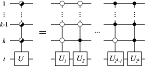
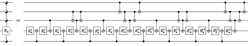
We define a uniformly controlled one-qubit gate to be a sequence of -fold controlled one-qubit gates in which all the control node configurations are utilized. All the one-qubit gates in the sequence act on the qubit , see Fig. 1. We use the symbol to denote a generic gate of this type, whereas the full definition of a particular gate entails the definition of all the gates .
Let us now consider the set of all gates of the form . Each is a -dimensional unitary operator that can be expressed as a direct sum of two-dimensional unitary operators , all operating in subspaces whose basis vectors differ only in the qubit : . Since all the operators in have identical invariant subspaces, the set is closed under multiplication and inversion: assuming that , we have
| (1) | ||||
| (2) |
These properties make a subgroup of . We point out that the matrix representations of all the gates in can be made simultaneously block-diagonal in the standard basis using a similarity transformation, namely a permutation of the qubits, in which the qubit is mapped to the qubit .
As a special case of uniformly controlled one-qubit gates, we define uniformly controlled rotations Möttönen et al. (2004a), in which all the two-dimensional operators belong to the same one-parameter subgroup of , e.g., the group of rotations around the axis. The elements of this particular subgroup are denoted as .
We extend the notation to accommodate also uniformly controlled multiqubit gates; by we denote a sequence of -fold controlled -qubit gates which act on the set of target qubits.
For convenience, we use a shorthand notation for the CNOT and the below defined two-qubit gate . The symbol is used to denote a CNOT whose control and target qubits are the ’th and ’th, respectively. Similarly, refers to a gate acting on the qubits and .
III Constant quantum multiplexor
Let us start by studying the two-qubit gate , the matrix representation of which consists of two unitary blocks. We show that it can be implemented using the multiplexor circuit presented in Fig. 2. The main difference between the presented construction and the original quantum multiplexor Shende et al. (2004a) is that we can effect the multiplexing operation using a fixed diagonal gate between the one-qubit gates. The tradeoff is an additional diagonal gate trailing the multiplexor. The advantage of the proposed construction is that the fixed gate can be implemented using a single CNOT, and in many applications the gate can be eliminated by merging it with an adjacent gate.
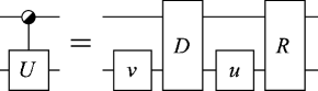
In matrix form, the implementation of the gate is
| (3) |
where , , and are unitary and and are diagonal unitary matrices. This yields the matrix equations
| (4) | ||||
| (5) |
or, equivalently,
| (6) | ||||
| (7) |
Equation (6) may be recast into a form reminiscent of an eigenvalue decomposition:
| (8) |
Note that is fixed by the matrices and , but can be chosen freely. By diagonalizing the matrix , we find the similarity transformation and the eigenvalue matrix . The matrix is obtained by inserting the results into Eq. (7).
Since , we may express it using the parametrization
| (9) |
where and . The characteristic polynomial of the matrix is
| (10) |
The main result of this section is that for any , we can find such that the roots of the polynomial are two fixed antipodal points on the unit circle in the complex plane. This is accomplished by choosing with
| (11) | ||||
| (12) |
Above, and are arbitrary integers with odd, and is the desired argument for one of the roots :
| (13) |
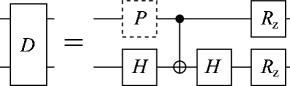
For convenience, let us choose . Hence the diagonal multiplexing gate obtains the fixed form . It can be realized straightforwardly using an Ising-type Hamiltonian or, alternatively, it can be decomposed into a CNOT and one-qubit gates as shown in Fig. 3. The resulting diagonal gate assumes the form of a uniformly controlled rotation in the most significant bit, . The entire circuit is shown in Fig. 4.
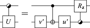
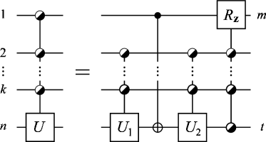
Now we turn our attention to the decomposition of an arbitrary gate, where . First we pick one of the control qubits, . This qubit pairs the two-dimensional invariant subspaces of the gate in a unique fashion. Hence the method of Eq. (3) may be used times in parallel, which effectively demultiplexes the chosen control qubit of the gate . The operation may be performed using a single gate and a compensating diagonal gate which again assumes the form of a uniformly controlled rotation :
| (14) |
Again, the gate may be replaced with a , see Fig. 3, since the required one-qubit gates may be absorbed into the surrounding gates. The final form of this step is presented in Fig. 5.
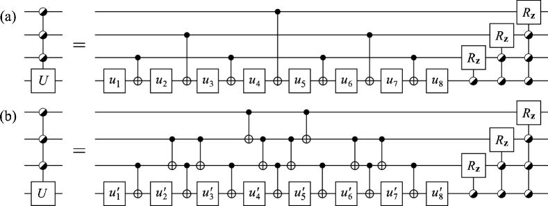
The decomposition of the gate can be continued recursively until only one-qubit gates, CNOTs and uniformly controlled gates are left. On the th level of the recursion, there are gates of the type . The next level of the recursion is obtained by demultiplexing the control qubit in all of these gates. Given that the leftmost gate is decomposed first, the resulting gate, being diagonal, can be commuted towards the right through the following gate and merged with the next gate. Hence, only the rightmost of the gates actually needs to be implemented on each level of the recursion. The resulting quantum circuit consists of two parts: an alternating sequence of one-qubit gates and CNOTs which we denote by , and a cascade of distinct uniformly controlled rotations, which corresponds to a single diagonal -qubit gate . Figure 6(a) presents this decomposition for the gate .
IV Examples
This section illustrates how the uniformly controlled one-qubit gates can be applied to efficiently solve two problems: the decomposition of a general -qubit gate and the local preparation of an arbitrary quantum state.
IV.1 Cosine-sine decomposition
Recently, we introduced a method Möttönen et al. (2004a) for decomposing a given general -qubit gate into a sequence of elementary gates using the cosine-sine decomposition (CSD). In this approach, the CS decomposition is applied recursively. Each recursion step decomposes a -fold uniformly controlled -qubit gate, where , into two -fold uniformly controlled -qubit gates and a single -fold uniformly controlled rotation:
| (15) | ||||
Above, is the set of target qubits for the gates and is the operational qubit for the step. Note that, in this notation, a gate may be denoted as , where is the set of all the qubits. When applied to an arbitrary -qubit gate, the recursion of Eq. (15) finally yields the decomposition
| (16) |
where is the so-called ruler function, given by Sloane’s sequence A001511 Guy (1994). The order of the noncommuting operators in the product is always taken to be from left to right. Note that the gates may as well be considered as general gates.
We continue by decomposing the uniformly controlled gates into one-qubit gates and CNOTs. Starting from the last gate in Eq. (16), we write the diagonal part separately:
| (17) |
The diagonal part can then be merged with the neighboring gate, which is transformed into a general gate of type . Again, the diagonal part can be separated and merged into the next gate . Continuing this process sequentially, we finally obtain
| (18) |
This decomposition involves gates of type , each of which takes CNOTs and one-qubit rotations to implement. The final diagonal gate is implemented using the same construction as in Ref. Möttönen et al. (2004a). After eliminating one CNOT and one-qubit gates, we obtain a circuit of CNOTs and one-qubit gates.
Table 1 presents a comparison between the improved CS decomposition and the most efficient previously known decomposition, the NQ decomposition Shende et al. (2004a). The number of CNOTs in the NQ decomposition is from Ref. Shende et al. (2004a). None of the other results have been published previously.
| Gate type | NQ | CS |
|---|---|---|
| fixed | ||
| or |
IV.2 Local state preparation
We have recently addressed Möttönen et al. (2004b) the problem of preparing an arbitrary -qubit quantum state starting from a state . The state preparation circuit first transforms the state into , and then, using the same strategy, backwards from to . The to transformation consists of a sequence of gate pairs
| (19) |
The effect of the gate pair on the state is to nullify half of its elements:
| (20) |
Hence, each successive gate pair nullifies half of the elements of the state vector that have not yet been zeroed, and we have up to a global phase.
Now we note that the pair of gates may be replaced by the gate
| (21) |
since the diagonal gate
| (22) |
does not mix the states;
| (23) |
After combining pairs of adjacent gates where we find that the entire circuit for transforming to requires CNOTs and one-qubit gates. If or coincides with one of the basis vectors , the gate counts are halved in the leading order. The method presented here yields a factor-of-two improvement in the gate counts compared to the previous results Möttönen et al. (2004b); Shende et al. (2004a). The circuit for this transformation is illustrated in Fig. 7.

V Linear chain of qubits with nearest-neighbor couplings
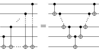
In most of the proposed physical implementations of quantum computers the qubits are spatially situated in such a way that only nearest-neighbor interactions are available. This does not imply that long-range gates are impossible to construct, but it renders such operations rather hard to implement. In this section we consider a quantum register consisting of a chain of qubits with only nearest-neighbor interactions and show that the construction presented for can be translated into an efficient nearest-neighbor CNOT implementation. The technique is based on the circuit identity shown in Fig. 8.
V.1 Uniformly controlled one-qubit gates
To find the recursion rule for the nearest-neighbor implementation of a uniformly controlled one-qubit gate, we modify the recursion rule expressed in Eq. (14) by inserting an identity in the form of a CNOT cascade and its inverse, a similar cascade, into the circuit next to the multiplexing gate . The cascades consist of the gates , where runs over the qubits connecting the qubits and . One of the cascades is absorbed into the following . The remaining cascade, together with the multiplexing CNOT, can be efficiently implemented using nearest-neighbor CNOTs as illustrated in Fig. 8.
The complexity of the nearest-neighbor implementation depends on the relative order of the target and control qubits, and the order in which the control qubits are demultiplexed. Since the number of nearest-neighbor CNOTs required increases linearly with the distance between the control and target qubits of the multiplexing CNOT, we first demultiplex the control qubits that are furthest apart from the target. Let us assume that a gate acts on a chain of consequent qubits. If , it is advantageous to use a sequence of swap gates to move the target qubit next to the center of the chain before the operation and back after it. A swap gate can be realized using three consecutive CNOTs. Taking this into account, a gate can be implemented using at most
| (24) |
nearest-neighbor CNOTs, where is the distance of the target qubit from the end of the chain. Figure 6(b) depicts the resulting circuit for the case and .
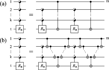
Now consider a -fold uniformly controlled rotation gate , where the rotation axis is perpendicular to the axis. It can be decomposed using the recursion step presented in Fig. 9(b). To minimize the CNOT count, we mirror at each recursion step the circuit of the latter uniformly controlled gate, which results in the cancellation of two nearest-neighbor CNOT cascades. For the same reason as in the previous paragraph, the recursion step is first applied to the control qubits furthest apart from the target. The implementation for the gate requires at most
| (25) |
nearest-neighbor CNOTs. Figure 10 displays an example circuit for the case and .
V.2 Cosine-sine decomposition
The decomposition of an arbitrary -qubit gate is achieved exactly as in Sec. IV.1, but now the order in which the CSD steps of Eq. (15) are applied to the qubits affects the final gate count. As seen in Eq. (24), it is favorable to have the target qubit of a uniformly controlled one-qubit gate as close to the center of the chain as possible. Consequently, we start the decomposition from the ends of the qubit chain, moving alternatingly towards the center. In this fashion, a general -qubit gate can be implemented using at most
| (26) |
nearest-neighbor CNOTs.
V.3 Local state preparation
With the help of the results derived above, the implementation of the general state preparation circuit using nearest-neighbor gates is straightforward. We follow the reasoning of Sec. IV.2 and simply replace the gates with their nearest-neighbor counterparts, using the decomposition derived in the beginning of this section. We find that the implementation of the state preparation circuit requires at most
| (27) |
nearest-neighbor CNOTs.
VI Discussion
In this paper we have studied the properties and the utilization of uniformly controlled one-qubit gates. We have derived a recursive circuit topology which implements an arbitrary -fold uniformly controlled one-qubit gate using at most one-qubit gates, CNOTs and a single diagonal -qubit gate. This construction is especially efficient if the gate is to implemented only up to a diagonal, e.g. when the phase factors of each basis vector can be freely chosen. We have also shown that this kind of freedom appears in the implementation of an arbitrary -qubit quantum gate and in the rotation of an arbitrary state vector into another. The leading-order complexity of the circuit for an arbitrary -qubit gate is CNOTs and an equal number of one-qubit gates, which are the lowest gate counts reported.
The techniques presented above are also amenable to experimental realizations of a quantum computer in which the quantum register consists of a one-dimensional chain of qubits with nearest-neighbor interactions. For example, the number of the nearest-neighbor CNOTs in the presented decomposition of an -qubit gate is in the leading order , which is appreciably below the lowest previously reported value of Shende et al. (2004a). Furthermore, the structure of the nearest-neighbor circuit allows several gate operations to be executed in parallel, which may further reduce the execution time of the algorithm.
In Ref. Möttönen et al. (2004a), it was speculated that the gate count of the quantum CSD could be reduced by combining adjacent uniformly controlled rotations into single uniformly controlled one-qubit gates, which was realized in this paper. To further reduce the number of CNOTs in the circuit, also the control nodes of the CNOTs should be used to separate the one-qubit gates carrying the degrees of freedom. However, uniformly controlled one-qubit gates cannot be used as the sole basic building blocks of the circuit in this kind of a construction.
Acknowledgements.
This research is supported by the Academy of Finland (project No. 206457, “Quantum Computing”). VB and MM thank the Finnish Cultural Foundation, JJV and MM the Jenny and Antti Wihuri Foundation, and JJV the Nokia Foundation for financial support.References
- Nielsen and Chuang (2000) M. A. Nielsen and I. L. Chuang, Quantum Computation and Quantum Information (Cambridge University Press, Cambridge, 2000).
- Shor (1994) P. W. Shor, in IEEE Proc. 35nd Annual Symposium on Foundations of Computer Science (1994), pp. 124–134.
- Galindo and Martin-Delgado (2002) A. Galindo and M. A. Martin-Delgado, Rev. Mod. Phys. 74, 347 (2002).
- Bullock et al. (2004) S. S. Bullock, G. K. Brennen, and D. P. O’Leary (2004), eprint quant-ph/0410116.
- Deutsch (1989) D. Deutsch, Proc. R. Soc. of Lond. A 425, 73 (1989).
- Barenco et al. (1995) A. Barenco, C. H. Bennett, R. Cleve, D. P. DiVincenzo, N. H. Margolus, P. W. Shor, T. Sleator, J. A. Smolin, and H. Weinfurter, Phys. Rev. A 52, 3457 (1995).
- Vartiainen et al. (2004) J. J. Vartiainen, M. Möttönen, and M. M. Salomaa, Phys. Rev. Lett. 92, 177902 (2004).
- Möttönen et al. (2004a) M. Möttönen, J. J. Vartiainen, V. Bergholm, and M. M. Salomaa, Phys. Rev. Lett. 93, 130502 (2004a).
- Shende et al. (2004a) V. V. Shende, S. S. Bullock, and I. L. Markov (2004a), eprint quant-ph/0406176.
- Möttönen et al. (2004b) M. Möttönen, J. J. Vartiainen, V. Bergholm, and M. M. Salomaa (2004b), eprint quant-ph/0407010.
- Shende and Markov (2004) V. V. Shende and I. L. Markov (2004), eprint quant-ph/0401162.
- Bullock and Markov (2004) S. S. Bullock and I. L. Markov, Quant. Inf. and Comp. 4, 27 (2004).
- Hogg et al. (1999) T. Hogg, C. Mochon, W. Polak, and E. Rieffel, Int. J. Mod. Phys. C10, 1347 (1999).
- Shende et al. (2004b) V. V. Shende, I. L. Markov, and S. S. Bullock, Phys. Rev. A 69, 062321 (2004b).
- Zhang et al. (2003) J. Zhang, J. Vala, S. Sastry, and K. B. Whaley, Phys. Rev. Lett. 91, 027903 (2003).
- Vatan and Williams (2004) F. Vatan and C. P. Williams, Phys. Rev. A 69, 032315 (2004).
- Vidal and Dawson (2004) G. Vidal and C. M. Dawson, Phys. Rev. A 69, 010301(R) (2004).
- Zurek (2003) W. H. Zurek, Rev. Mod. Phys. 75, 715 (2003).
- Guy (1994) R. K. Guy, in Unsolved Problems in Number Theory, 2nd ed. (Springer-Verlag, New York, 1994), p. 224.