Casimir force between designed materials:
what is possible and what not
Abstract
We establish strict upper limits for the Casimir interaction
between multilayered structures of arbitrary dielectric or diamagnetic
materials. We discuss the appearance of different power laws
due to frequency-dependent material constants. Simple analytical
expressions are in good agreement with numerical calculations based on
Lifshitz theory. We discuss the improvements required for current
(meta) materials to achieve a repulsive Casimir force.
Dated: 20 Oct 2005, Europhysics Letters, in press.
PACS. 42.50.Pq – Cavity quantum electrodynamics;
42.50.Lc – Quantum fluctuations, quantum noise;
78.67.-n – Optical properties of low-dimensional, mesoscopic,
and nanoscale materials and structures
1 Introduction
The optical properties of materials that show both a dielectric and magnetic response, have recently attracted much attention (see [1] for a review). A number of striking phenomena like perfect lensing and a reversed Doppler effect have been predicted, and experimenters have begun to explore the large parameter space of structural units that can be assembled into artificial materials. Breakthroughs have been reported on the way towards designed susceptibitilies in the near-infrared and visible spectral range [2, 3]. Quantum electrodynamics in meta materials has recently been explored with particular emphasis on left-handed or negative-index materials [4, 5]. We discuss here to what extent the Casimir interaction between two meta material plates can be manipulated by engineering their magneto-dielectric response. Strict limits for the Casimir interaction are proven that apply to all causal and linear materials, including both bulk and multilayer structures. We illustrate these results by computations of the Casimir pressure, considering materials with frequency-dispersive response functions like those encountered in effective medium theories. We derive power law exponents and prefactors and find that a strongly modified Casimir interaction is possible in a range of distances around the resonance wavelength of the response functions. We give estimates for the required temperature range and structure size: it is not unreasonable to expect that improvements in fabrication and detection will allow for experimental observations.
One of the most striking changes to the Casimir interaction is a cross over to repulsion. This has been predicted previously for idealized magnetodielectric materials [6, 7, 8] and objects suspended in a liquid [9, 10]. In the latter case, repulsion has been observed experimentally with colloidal particles [11] and is also used in a recent proposal for measuring Casimir torques [12]. Casimir repulsion between mirrors separated by vacuum requires a strong magnetic response [7, 13] that hardly occurs in conventional ferromagnets [14, 15]. Indeed, to manipulate the Casimir force in the micrometer range and below, where it can be conveniently measured, the key challenge is to achieve a magnetic susceptibility at high frequencies, approaching the visible range. Now, there is a well-known argument due to Landau, Lifshitz, and Pitaevskii that in the visible [16]. This objection, however, only applies to materials whose magnetization is of atomic origin, where the magnetic susceptibility is . An array of split ring resonators with sub-wavelength size typically gives, on the contrary, , where is the resonance frequency and the filling factor [17, 18]. As we illustrate below, artificial materials that are structured on the sub-micron scale are promising candidates for a strongly modified Casimir interaction.
2 Lifshitz theory
For two perfectly conducting plates held at zero temperature and separated by a distance , Casimir derived a force per unit area given by [19]. We use the convention that corresponds to attraction. For linear media with complex, frequency-dependent material parameters, the force can be computed from Lifshitz theory [20]. This expression has been re-derived, for plates of arbitrary material and for multilayer mirrors, using different methods [21, 22, 23, 25, 26, 27, 28, 29, 30, 31, 32]. At finite temperature, it can be written in the form
| (1) |
where the sum is over the imaginary Matsubara frequencies (the term being multiplied by ), and is related to the wave vector component perpendicular to the mirrors, . The (, ) are the reflection coefficients at mirror for electromagnetic waves with polarization [22, 23]. For homogeneous, thick plates, they are given by
| (2) |
(exchange and for ). The zeros of at real frequencies define the eigenmodes of the cavity formed by the two mirrors.
3 Strict limits
To derive upper and lower limits for , we use that the Kramers-Kronig relations [16] imply real and positive material functions at imaginary frequencies, , provided the material is passive (non-negative absorption ). As a consequence, the Fresnel formulas (2) imply , and we find
| (3) |
with the stronger inequalities holding for identical plates. In the latter case, the Casimir force is hence necessarily attractive. The inequalities (3) saturate for a perfectly conducting mirror facing a perfectly permeable one (, , say), and for identical, perfectly reflecting mirrors, respectively. The resulting forces at zero temperature are [20, 6]
| (4) |
In the high-temperature limit, we get similarly [24] by keeping in Eq.(1) only the term in the sum.
Consider now a mirror made from layers of arbitrary passive materials. Reflection coefficients for such a system can be obtained recursively. For a layer ‘’ separating a medium ‘’ from a substrate ‘’, for example,
| (5) |
where () describes the reflection from the interface (), respectively, and is the layer thickness [33, 34]. If the substrate is a multilayer system itself, is the corresponding reflection coefficient. For the imaginary frequencies occurring in the Lifshitz expression (1), the wavevector in the layer is purely imaginary, , and single-interface coefficients are real [Eq.(2)]. From Eq.(5), they remain real for multilayer mirrors. In addition, the mapping is a conformal one, and if is real and , the interval is mapped onto itself. For multilayer mirrors, we thus obtain again the inequalities . This generalizes the limits of Refs. [35, 32] that are obtained only for layered dielectric mirrors, using transfer matrices.
4 Casimir interaction between metamaterials
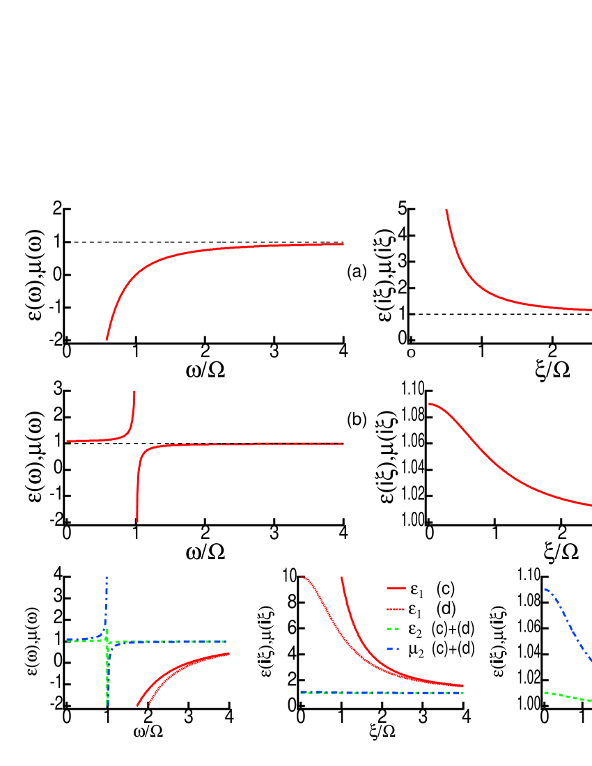
To illustrate these generally valid results, we focus on meta materials described by effective medium theory [1, 17, 18]. We adopt Lorentz-Drude formulas for and
| (6) |
Regarding the permeability, we have taken the limit of weak absorption and computed in terms of using the Kramers-Kronig relations. This is necessary to ensure high-frequency transparency of the medium. We denote in the following by a typical resonance or plasma frequency occurring in Eqs.(6). The corresponding wavelength, , provides a convenient distance scale. Note that a (magnetic) resonance wavelength as short as has already been achieved with material nanofabrication [3]. The key advantage of meta materials is that their electric and magnetic ‘plasma frequencies’ and are fairly large as well: a value of is typical for a split-ring resonator array with period and filling factor [17]. This property is also necessary, of course, to achieve a left-handed medium (, for some real frequencies). The magnetic plasma frequencies occurring in conventional ferromagnets are much smaller [14], and the impact on the Casimir interaction is weak, as reported recently [13].
In the plots shown below, the Casimir pressure is normalized to [see after Eq.(7)]. In order of magnitude, this corresponds to at a distance . This can be measured with sensitive torsion balances [36, 37] or cantilevers [38, 39]. We plot in Fig.1 the result of a numerical integration of Eq.(1), the curves corresponding to different material pairings. One sees that in all cases, the force satisfies the limits (4) that exclude the shaded areas. We observe that materials with negative index of refraction around show a strongly reduced attraction (Fig.1(b)). This can be attributed to the reduced mirror reflectivity due to impedance matching. Casimir repulsion is achieved for some distances between mirrors made from different materials (Fig.1(c,d)). At short distance, i.e. , even these pairings show attraction with a power law . Coating one mirror with a magnetic layer (Fig.1(c)), there is a sign change around the layer thickness : for , the layer behaves like a thick plate, and its material parameters lead to repulsion. The layer can be ignored for , and one recovers the attraction between the (identical) substrates. This is consistent with asymptotic analysis based on the reflection coefficient (5), as we outline below. Detailed calculations show that a large resonance frequency is not sufficient to achieve repulsion, the oscillator strength of the resonances (proportional to and ) must be large enough so that . As the temperature is raised, the distance range where repulsion is observed disappears, see Fig.2. One then finds a power law at large distance as well.
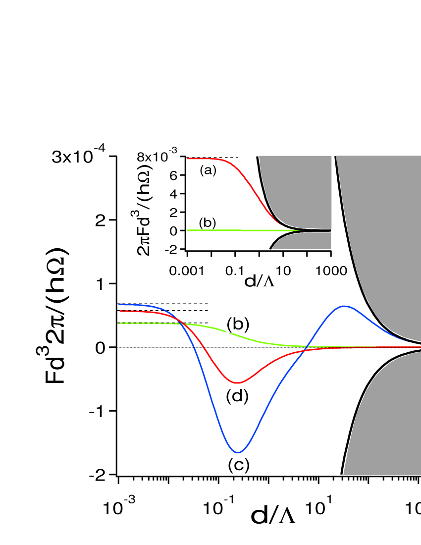
Dashed lines: short-distance asymptotics with coefficient (7), providing another upper limit for homogeneous mirrors. Curve (a) (inset): two identical non-magnetic Drude metals (in Eq.(6), , , , ). Curve (b): two identical left-handed meta materials with overlapping dielectric and magnetic resonances (, , , ). Curve (c): two identical non-magnetic Drude metals one of which is coated with a left-handed meta material (Drude metals with , , ; left-handed coating with thickness and material parameters (dominantly magnetic response) , , , ). Curve (d): two meta materials, one purely dielectric, the other mainly magnetic (, , , , , , ).
The different regimes of Fig.1 can be understood from an asymptotic analysis of Eq.(1). At short distance (), the integral is dominated by a region in the --plane where the Fresnel coefficients (2) take the nonretarded forms assuming that and similarly unless . Proceeding like Lifshitz [20, 40], yields to leading order a power law with a positive Hamaker constant given by
| (7) |
where . It must be noted that for the special case of homogeneous plates, this asymptotic expression actually provides another, much stricter, upper limit to the Casimir force, since , and is a monotonous function (see Fig.1). In order of magnitude, at low temperatures (). Compared to ideal mirrors, dispersive plates thus show a much weaker Casimir interaction that is in general attractive (Fig.1 and Ref.[35]). At larger distances, , the Casimir force follows a power law, and repulsion is found provided one of the materials is dominantly magnetic. Here, the non-dispersive results of Ref.[7] are recovered. Finally, for , the leading order force is the term in the sum (1), again an attractive law, with a coefficient given by an expression similar to (7), but involving the static material constants, see [7].
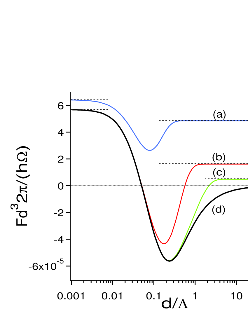
The impact of temperature is illustrated in Fig.2: at high temperature, , the second Matsubara frequency falls already into the mirrors’ transparency zone, and the power law is valid at all distances. As , the intermediate repulsive zone appears in the range . A good agreement with the analytical asymptotics is found outside this zone, as shown by the dashed lines. For the resonance wavelength mentioned above, cooling to a temperature is required to ‘open up’ the repulsive window. This temperature increases, of course, with materials whose response extends to higher frequencies.
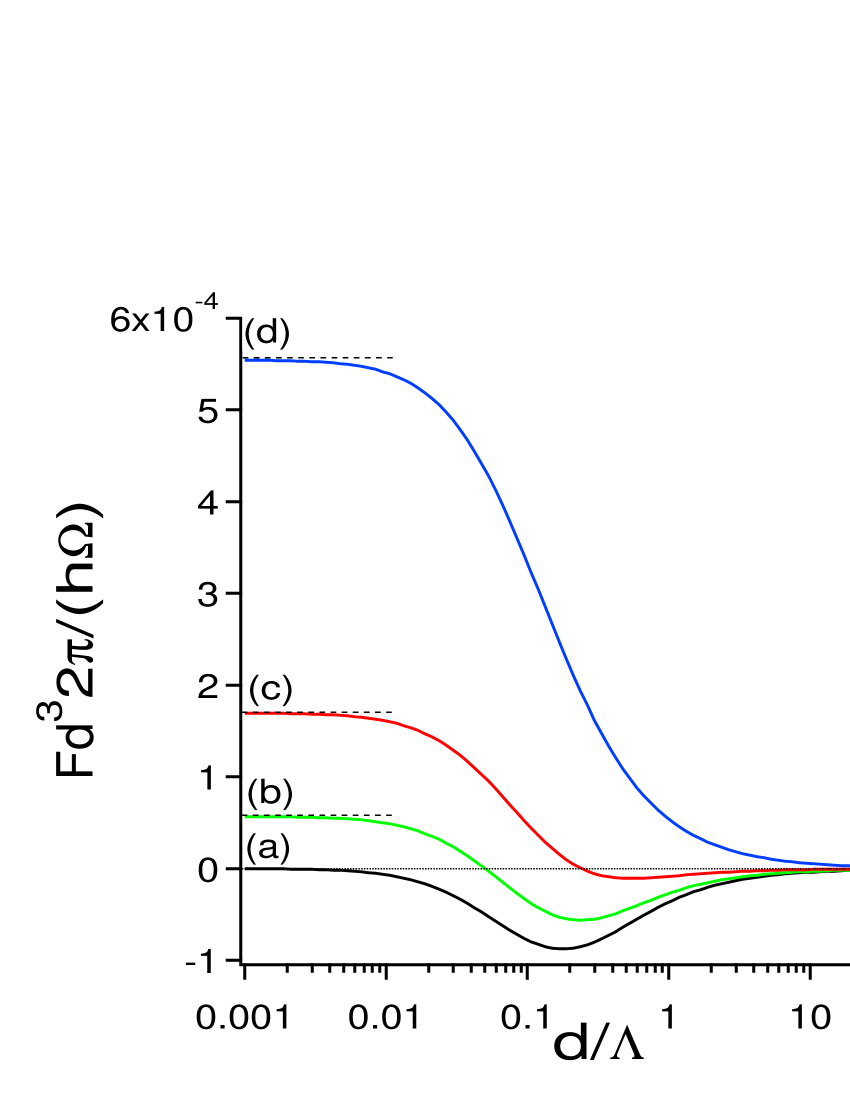
Finally, we would like to illustrate the kind of peculiar asymptotics that becomes possible with carefully matched material parameters. This follows Ref.[21] that computes the Van der Waals force on a water film coated on both sides by lipid membranes, finding a weak dependence on the ultraviolet frequency range because both materials have a similar electron density. Consider thus a liquid-filled gap with a similar electron density as medium 2 so that , and a permeability matched to medium 1. For simplicity, we assume that these equalities hold at all frequencies. In this case, we can show that the force is repulsive at all distances, even at finite temperature. Indeed, both contributions in Eq.(7) vanish, and the leading order term for high temperatures also vanishes. The high-temperature limit is given by the term in (1). This gives a distance dependence proportional to similar to what has been observed in some experiments with colloids (mentioned in [41]). As the temperature is lowered, this exponential regime still applies for . If , the regime of Ref. [7] exists at intermediate distances . The short distance regime sets in for , and an analysis similar to the one leading to Eq.(7) gives ()
| (8) |
with . At short distance, the sum is dominated by the first term, so that to leading order, we get a repulsive power law (Fig.3(a)). In order of magnitude, and therefore again , with a cross over occurring around (see Fig.3(a)). Due to our assumption of a perfect matching , this kind of behaviour seems quite remote from experimental reality. As shown in Fig.3(b–d), a slight mismatch between the dielectric functions of liquid and plate leads back to an attractive force, first at short distances, then suppressing the repulsive window altogether.
5 Conclusion
We have generalized strict upper and lower limits for the Casimir force. We have shown that a strongly modified Casimir force can occur between dispersive and absorbing mirrors with a sufficiently large magnetic susceptibility, extending results restricted to non-dispersive materials [7]. The most promising way to achieve this repulsion seems the use of meta materials engineered at scales between the nanometer and the micron because they provide a fairly large magnetic oscillator strength. Our results are intrinsically limited to distances by our use of effective medium theory. Sufficiently small structures and sufficiently low temperatures then ensure that in the range , the Casimir interaction can be strongly altered: even if repulsion cannot be achieved in a first step, we expect a significant reduction of the Casimir attraction at distances of a few microns (Fig.1).
Our thanks for comments and discussion goes to J.-J. Greffet, J.-P. Mulet, M. Wilkens, M. Tomaš, C. Genet, A. Lambrecht, S. Reynaud, and L. Pitaevskii. We thank anonymous referees for constructive criticism. We acknowledge financial support from the bilateral French-German programme “Procope” under project numbers 03199RH and D/0205739.
References
- [1] S. A. Ramakrishna, Rep. Prog. Phys. 68, 449 (2005).
- [2] T. J. Yen et al., Science 303, 1494 (2004).
- [3] S. Linden, C. Enkrich, M. Wegener, J. Zhou, T. Koschny, and C. M. Soukoulis, Science 306, 1351 (2004).
- [4] V. V. Klimov, Opt. Commun. 211, 183 (2002).
- [5] J. Kästel and M. Fleischhauer, Phys. Rev. A 71, 011804 (2005).
- [6] T. H. Boyer, Phys. Rev. A 9, 2078 (1974).
- [7] O. Kenneth, I. Klich, A. Mann, and M. Revzen, Phys. Rev. Lett. 89, 033001 (2002).
- [8] T. H. Boyer, American Journal of Physics 71, 990 (2003).
- [9] U. Hartmann, Phys. Rev. B 43, 2404 (1991).
- [10] J. N. Israelachvili, Intermolecular and surface forces, 2nd ed. (Academic Press, San Diego, 2000).
- [11] S.-W. Lee and W. M. Sigmund, J. Coll. Int. Sci. 243, 365 (2001).
- [12] J. N. Munday, D. Iannuzzi, Y. Barash, and F. Capasso, Phys. Rev. A 71, 042102 (2005).
- [13] M. S. Tomaš, Phys. Lett. A 342, 381 (2005).
- [14] R. E. Camley, M. R. F. Jensen, S. A. Feiven, and T. J. Parker, J. Appl. Phys. 83, 6280 (1998).
- [15] D. Iannuzzi and F. Capasso, Phys. Rev. Lett. 91, 029101 (2003); O. Kenneth, I. Klich, A. Mann, and M. Revzen, ibid. 91, 029102 (2003).
- [16] L. D. Landau, E. M. Lifshitz, and L. P. Pitaevskii, Electrodynamics of continuous media, 2nd ed. (Pergamon, Oxford, 1984).
- [17] J. B. Pendry, A. J. Holden, D. J. Robbins, and W. J. Stewart, IEEE Trans. Microwave Theory Tech. 47, 2075 (1999).
- [18] D. R. Smith, P. Rye, D. C. Vier, A. F. Starr, J. J. Mock, and T. Perram, IEICE Trans. Electron. E87-C, 359 (2004).
- [19] H. B. G. Casimir, Proc. Kon. Ned. Akad. Wet. 51, 793 (1948).
- [20] E. M. Lifshitz, Soviet Phys. JETP 2, 73 (1956), [J. Exper. Theoret. Phys. USSR 29, 94 (1955)].
- [21] V. A. Parsegian and B. W. Ninham, Nature 224, 1197 (1969).
- [22] B. W. Ninham and V. A. Parsegian, J. Chem. Phys. 53, 3398 (1970).
- [23] P. Richmond and B. W. Ninham, J. Phys. C: Solid State Phys. 4, 1988 (1971).
- [24] F. C. Santos, A. Tenório, and A. C. Tort, Phys. Rev. D 60, 105022 (1999).
- [25] K. Schram, Phys. Lett. 43A, 282 (1973).
- [26] J. Schwinger, L. L. DeRaad, Jr., and K. A. Milton, Ann. Phys. (N.Y.) 115, 1 (1978).
- [27] D. Kupiszewska, Phys. Rev. A 46, 2286 (1992).
- [28] F. Zhou and L. Spruch, Phys. Rev. A 52, 297 (1995).
- [29] G. L. Klimchitskaya, U. Mohideen, and V. M. Mostepanenko, Phys. Rev. A 61, 062107 (2000).
- [30] R. Esquivel-Sirvent, C. Villarreal, and G. H. Cocoletzi, Phys. Rev. A 64, 052108 (2001).
- [31] M. S. Tomaš, Phys. Rev. A 66, 052103 (2002).
- [32] C. Genet, A. Lambrecht, and S. Reynaud, Phys. Rev. A 67, 043811 (2003).
- [33] M. Born and E. Wolf, Principles of Optics, 6th ed. (Pergamon Press, Oxford, 1959).
- [34] P. Yeh, Optical Waves in Layered Media (John Wiley & Sons, New York, 1988).
- [35] A. Lambrecht, M.-T. Jaekel, and S. Reynaud, Phys. Lett. A 225, 188 (1997).
- [36] S. K. Lamoreaux, Phys. Rev. Lett. 78, 5 (1997), erratum: 81 (1998) 5475.
- [37] H. B. Chan, V. A. Aksyuk, R. N. Kleiman, D. J. Bishop, and F. Capasso, Science 291, 1941 (2001).
- [38] U. Mohideen and A. Roy, Phys. Rev. Lett. 81, 4549 (1998).
- [39] G. Bressi, G. Carugno, R. Onofrio, and G. Ruoso, Phys. Rev. Lett. 88, 041804 (2002).
- [40] C. Henkel, K. Joulain, J.-P. Mulet, and J.-J. Greffet, Phys. Rev. A 69, 023808 (2004).
- [41] H. D. Ackler, R. H. French, and Y.-M. Chiang, J. Coll. Int. Sci. 179, 460 (1996).