Theory of control of spin/photon interface for quantum networks
Abstract
A cavity coupling a charged nanodot and a fiber can act as a quantum interface, through which a stationary spin qubit and a flying photon qubit can be inter-converted via cavity-assisted Raman process. This Raman process can be controlled to generate or annihilate an arbitrarily shaped single-photon wavepacket by pulse-shaping the controlling laser field. This quantum interface forms the basis for many essential functions of a quantum network, including sending, receiving, transferring, swapping, and entangling qubits at distributed quantum nodes as well as a deterministic source and an efficient detector of a single photon wavepacket with arbitrarily specified shape and average photon number. Numerical study of noise effects on the operations shows high fidelity.
pacs:
03.67.-a, 42.50.Pq, 78.47.+p,78.67.HcQuantum networks composed of local nodes and quantum channels are essential for quantum communication and desirable for scalable and distributed quantum computation Cirac et al. (1999); DiVincenzo (2000). Spins in quantum dots Loss and DiVincenzo (1998) or stable levels of atoms or ions Monroe et al. (1995); Cirac and Zoller (1995) are good candidates for stationary qubits which can be locally stored and manipulated Imamoğlu et al. (1999); Piermarocchi et al. (2002); Chen et al. (2003). Photons in optical fibers or waveguides are ideal flying qubits for carrying quantum information between the local nodes. A quantum interface inter-converting local and flying qubits is the key component of the quantum network. A very recent experiment demonstrating entanglement between photon polarizations and states in an atom Blinov et al. (2004) represents a breakthrough in this direction. Another milestone toward quantum networks is the proposal of Cirac et al. based on cavity-assisted Raman processes Cirac et al. (1997), which employs time-symmetrical carrier pulses and mutually time-reversed operations at two nodes to transfer a qubit state from one node to another.
This Letter proposes a faithful and controllable spin/photon quantum interface without imposing the symmetry requirement between two nodes. It also describes a semiconductor quantum dot and cavity operation for this quantum interface and, from it, the architecture of a solid-state quantum network.
We note that the state-transfer process proposed in Ref. Cirac et al., 1997 can be separated into two steps: the sending operation at one node which maps a stationary qubit into a flying qubit by the evolution , and the receiving operation at another node which maps the flying qubit into a stationary one, where and are the stationary qubit states and the flying qubit is represented by the vacuum state and a single-photon state with wavepacket . We will show that both the sending and receiving processes can be independently controlled by shaping the laser pulses. Two aspects of the process are controllable: the production of an arbitrarily shaped pulse provided that it is sufficiently smooth and the operation of the Raman process as a partial cycle, in which the initial state is mapped into an entangled state for any .
With such controllability in hand, this quantum interface can accomplish many essential functions of a quantum network: (i) It can send a flying quantum state and can also function as a deterministic source of single-photons with arbitrary pulse shape and controllable photon number. (ii) It can receive a flying quantum state, being an efficient single-photon detector provided that the incoming photon pulse shape is known. (iii) The sending and receiving processes combined transfer a state from one node to another. (iv) An incoming flying qubit may be swapped with a stationary qubit which enables the swap of two remote qubits. (v) An entangled state of the stationary and flying qubits is produced in a partial Raman cycle. (vi) Two stationary qubits separated far away are entangled when the photon state generated by the partial Raman cycle is mapped into a stationary qubit.
A substantial list of recent experimental advances on optical manipulation of excitons in single quantum dots Li et al. (2003), nanodot-microsphere coupling Fan et al. (2000), cavity-fiber coupling Vahala (2003), and fabrication of high-quality microcavities and waveguides, both on semiconductor surfaces Vahala (2003) and in photonic crystals Scherer et al. (2002); Akahane et al. (2003), makes it fairly realistic for us to outline a physical plan for a solid-state quantum network for scalable and distributed processing of quantum information [see Fig. 1 (a)]. In this network structure, a local node is formed by a cluster of charged quantum dots, and the electron spins representing stationary qubits, having memory lifetime s de Sousa and Das Sarma (2003), can be optically manipulated in the time scale ps Imamoğlu et al. (1999); Piermarocchi et al. (2002); Chen et al. (2003). Fibers or waveguides can act as sufficiently lossless quantum channels for flying photons. Since it takes less than 1 ns for a photon to travel 10 cm, the quantum network can be easily scaled from nano-devices to centimeter-sized chips. The loss or decoherence of photons in fibers is negligible in such a short distance and may be ameliorated by quantum repeaters in the long distance transfer Duan et al. (2001). The quantum interface is made up of a high- microcavity coupling a quantum dot and a fiber or waveguide [see Figure 1(b)]. The dot-cavity-fiber structure also allows the ultrafast initialization and non-destructive readout of the spin qubit in the dot Liu et al. (2004), essential for quantum error correction and scalable quantum computation.
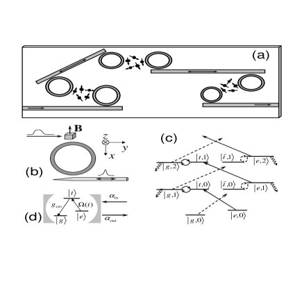
The detailed optical process involved in the quantum interface is depicted in Fig. 1(c). The qubit is represented by the two spin states and which is split by a static magnetic field. The intermediate states in the Raman process are the two degenerate trion states and . The geometrical configuration and optical polarizations Yao et al. (2004) are set such that the cavity mode of frequency couples only the transitions and with coupling constant , and the controlling laser of frequency couples only the transitions an with the complex Rabi frequency . The Raman process satisfies the resonance condition: . By the Zeeman splitting and the selection rules, the trion state is off-resonantly coupled to the laser beam and the cavity modes (shown by dashed lines in the figure). The cavity mode is coupled to the fiber continuum by the coupling constant .
The basic Raman process is quite simple. At a sending node, the laser field first resonantly excites the spin state to the trion state , then the trion state is resonantly coupled to the cavity state , and finally the cavity state jumps to the spin state by emitting a photon into the quantum channel. The receiving mode is just the time reversed process. The off-resonant excitation which leads to rather complicated dynamics involving multi-photon states in the cavity is rendered negligible by a strong magnetic field making the Zeeman splitting much larger than the cavity-dot coupling and the Rabi frequency. As shown in Fig. 1(d), the optical process is then simplified to a cavity-assisted resonant Raman process in a -type three-level system. In this simplified system, we can find, for any designated shape and average photon number of the emitted single-photon wavepacket, an analytical solution of the pulse shape of the laser field (or Rabi frequency). With this analytically obtained Rabi frequency as the controlling input, numerical calculations including the non-resonant transitions and realistic decoherence have been performed and high fidelity of desired operations at the quantum interface is demonstrated.
We first present the analytical solution of the laser pulse for the controlled Raman transition converting a spin qubit state to a flying photon state. We note that the simplified system depicted in Fig. 1(d), under the optical excitation and the cavity-dot and cavity-channel interaction, has two invariant Hilbert subspaces, with the basis and , respectively (where denotes the one-photon Fock state of the fiber mode with frequency ). So the evolution of the system can be described by the state , where
Within the Weisskopf-Wigner approximation, the equation of motion for the resonant Raman process in the interaction picture can be derived as
| (1a) | |||||
| (1b) | |||||
| (1c) | |||||
| (1d) | |||||
where gives the cavity damping rate, and with and with are the incoming and outgoing pulse of the photon in the quantum channel, respectively. The quantum fluctuation caused by the quantum channel is on the order of and thus the Weisskopf-Wigner approximation is well justified here.
In the process of mapping the spin qubit to the photon qubit, there is no incoming photon, so the initial conditions are: , , and . Eq. (1) can be analytically solved as
| (2a) | |||||
| (2b) | |||||
| (2c) | |||||
where is the normalized wavepacket of the emitted photon, and is the average photon number. For a photon number and a pulse shape arbitrarily specified, the amplitude of the cavity mode is determined by Eqs. (1c) and (1d) as , and in turn the controlling laser pulse can be analytical obtained from Eq. (2c). Note that the solution exists only when the right-hand side of Eq. (2a) is positive which requires the specified output pulse be sufficiently smooth, i.e., the pulse generation process be slower than the cavity decay and the dot-cavity tunnelling (with time scales and , respectively). At the remote future time , the photon emission process is completed, i.e., , so with the controllable phase independent of the initial superposition (see Eq. (2b)). Compared to Ref. Cirac et al., 1997, the solution here is not limited in the perturbative regime, and thus enables the design of ultrafast operation.
When the full Raman transition is completed, and , thus the spin qubit is mapped into the flying qubit by the transformation
| (3) |
The mapping operation also functions as deterministic generation of a single-photon wavepacket with any desired pulse shape and average photon number .
The Raman cycle can also be controlled such that . In this case, the initial state is transformed into an entangled state of the stationary spin and the flying photon
| (4) |
The entanglement entropy can be set any value between 0 and 1 depending on the rotating angle .
The Raman process at the receiving node is basically the time-reversal of the sending process. With the initial spin state and the incoming photon state , the mapping transformation is
| (5) |
As in the sending process, the incoming photon pulse can be arbitrarily specified provided that it is smooth enough, and the photon is absorbed without reflection. As the spin state converted from the photon state can be read out non-destructively Liu et al. (2004), the receiving node can also act as an efficient photon detector which measures the photon number state given the photon pulse shape is known.
For swap operations, the waveguide connecting the two nodes should be long enough to make the photon travelling time longer than the operation time. If the operation at the sending node has been designed to produce an entangled state of the spin and the photon, the mapping process at the receiving node will just produce a non-locally entangled state of the two spins by the transformation
| (6) | |||||
The fidelity of all the quantum operations described above can be evaluated by numerical simulations including the undesired non-resonant dynamics, and unavoidable decoherence. The decoherence results mainly from the trion decay due to spontaneous emission and the intrinsic loss of the cavity mode, while the fiber loss and the spin relaxation, though unavoidable, are negligible on the time-scale ( ps) and the space-scale ( cm) considered here. The trion decay rate is chosen to be a realistic value of eV, and the intrinsic loss rate of a high- cavity is assumed to be eV (corresponding to a -factor ). The cavity-fiber tunnelling rate is set meV and the dot-cavity coupling constant is chosen as meV. The Zeeman splitting of the spin under a quantizing magnetic field is 1 meV, chosen much larger than the Rabi frequency and the cavity-dot coupling in order to suppress the undesired effects: the non-resonant excitation of the multi-photon states and AC Stark shift of the energy levels. Numerical test shows that including up to 3-photon states is enough to obtain convergent results. While the multi-photon states of fiber modes can be projected into the error subspace in the state-sending operation, they can still carry quantum information in the state-transfer or non-local entanglement operations, thus the quantum trajectory method Cirac et al. (1997); Carmichael (1993) has been employed in these cases to include the effect of multi-photon pulses propagating in the fiber.
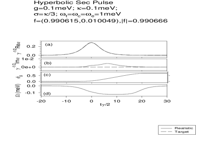
To demonstrate the efficiency of the quantum interface, we present in Fig. 2 the simulation result of mapping a spin state to a flying photon wavepacket with the pulse shape designated to be a sech-function as . The actual final state of the evolution can be generally written as Due to the non-resonant excitation, the wavefunction can have an error part which lies outside the qubit-subspace. The large Zeeman splitting and the smooth switch-on and off of the laser field make this error less than . Another error due to the non-resonant coupling is the AC Stark shift of the energy levels, which induces a phase drift of the ground state . This phase drift (), however, is independent of the coefficients as the two excitation pathways starting respectively from and are independent of each other [see Fig. 1 (c)], so it can be compensated by a trivial single-qubit operation. The fidelity of the pulse generation is high. Including the leakage into the error subspace, the overall fidelity of the mapping operation is still larger than . Due to the non-perturbative optical pumping and dot-cavity coupling, the whole mapping process can be completed within 300 ps. The simulation of the photon absorption process shows an overall fidelity greater than as well.
In the simulations of state-transfer and non-local entanglement, the two remote nodes are assumed identical, but it should be noted that in our scheme the two nodes can be controlled independently and thus can be designed with different parameters if desired. The state transfer process has been simulated with various carrier pulse shapes. The overall fidelity, with the phase drift compensated, is greater than for a sech-pulse . Using the same carrier pulse, we have also simulated the creation of non-local entanglement. With the Rabi frequency analytically designed for a Bell state , the actual final state of the simulation turns out to be . While the probability of leakage out of the qubit subspace is less than , the spins are entangled with entanglement entropy and fidelity .
In summary, controllable and high-fidelity quantum interface for inter-converting spin/photon qubits, based on cavity-assisted Raman process, can be used to construct a scalable quantum network with solid-state elements including charged quantum dots, micro-rings (or microcavities), and waveguides (or fibers). The theory assumes a knowledge of the parameters of the coupled system. It paves the way for further exploration of quantum feeback Wiseman and Milburn (1993) and learning algorithms Rabitz et al. (2000) for this system.
This Work was supported by NSF DMR-0099572, ARDA/ARO DAAD19-02-1-0183, and QuIST/AFOSR F49620-01-1-0497.
References
- Cirac et al. (1999) J. I. Cirac, A. K. Ekert, S. F. Huelga, and C. Macchiavello, Phys. Rev. A 59, 4249 (1999).
- DiVincenzo (2000) D. DiVincenzo, Fortschr. Der Physik 48, 771 (2000).
- Loss and DiVincenzo (1998) D. Loss and D. P. DiVincenzo, Phys. Rev. A 57, 120 (1998).
- Monroe et al. (1995) C. Monroe, D. M. Meekhof, B. E. King, W. M. Itano, and D. J. Wineland, Phys. Rev. Lett. 75, 4714 (1995).
- Cirac and Zoller (1995) J. I. Cirac and P. Zoller, Phys. Rev. Lett. 74, 4091 (1995).
- Imamoğlu et al. (1999) A. Imamoğlu, D. D. Awschalom, G. Burkard, D. P. DiVincenzo, D. Loss, M. Sherwin, and A. Small, Phys. Rev. Lett. 83, 4204 (1999).
- Piermarocchi et al. (2002) C. Piermarocchi, P. Chen, L. J. Sham, and D. G. Steel, Phys. Rev. Lett. 89, 167402 (2002).
- Chen et al. (2003) P. Chen, C. Piermarocchi, L. J. Sham, D. Gammon, and D. G. Steel, Phys. Rev. B 69, 075320 (2003).
- Blinov et al. (2004) B. B. Blinov, D. L. Moehring, L.-M. Duan, and C. Monroe, Nature (London) 428, 153 (2004).
- Cirac et al. (1997) J. I. Cirac, P. Zoller, H. J. Kimble, and H. Mabuchi, Phys. Rev. Lett. 78, 3221 (1997).
- Li et al. (2003) X. Li, Y. Wu, D. Steel, D. Gammon, T. H. Stievater, D. Katzer, D. S. Park, C. Piermarocchi, and L. J. Sham, Science 301, 809 (2003).
- Fan et al. (2000) X. D. Fan, P. Palinginis, S. Lacey, H. L. Wang, and M. C. Lonergan, Opt. Lett. 25, 1600 (2000).
- Vahala (2003) K. J. Vahala, Nature (London) 424, 839 (2003).
- Scherer et al. (2002) A. Scherer, O. Painter, J. Vuckovic, M. Loncar, and T. Yoshie, IEEE Transcations on Nanotechonology 1, 4 (2002).
- Akahane et al. (2003) Y. Akahane, T. Asano, B.-S. Song, and S. Noda, Nature (London) 425, 944 (2003).
- de Sousa and Das Sarma (2003) R. de Sousa and S. Das Sarma, Phys. Rev. B 68, 115322 (2003).
- Duan et al. (2001) L. M. Duan, M. D. Lukin, J. I. Cirac, and P. Zoller, Nature 414, 413 (2001).
- Liu et al. (2004) R. B. Liu, W. Yao, and L. J. Sham, unpublished (2004).
- Yao et al. (2004) W. Yao, R. B. Liu, and L. J. Sham, Phys. Rev. Lett. 92, 217402 (2004).
- Carmichael (1993) H. J. Carmichael, Phys. Rev. Lett. 70, 2273 (1993).
- Wiseman and Milburn (1993) H. M. Wiseman and G. J. Milburn, Phys. Rev. Lett. 70, 548 (1993).
- Rabitz et al. (2000) H. Rabitz, R. de Vivie-Riedle, M. Motzkus, and K. Kompa, Science 288, 824 (2000).