Transformation of quantum states using uniformly controlled rotations
Abstract
We consider a unitary transformation which maps any given state of an -qubit quantum register into another one. This transformation has applications in the initialization of a quantum computer, and also in some quantum algorithms. Employing uniformly controlled rotations, we present a quantum circuit of CNOT gates and one-qubit elementary rotations that effects the state transformation. The complexity of the circuit is noticeably lower than the previously published results. Moreover, we present an analytic expression for the rotation angles needed for the transformation.
pacs:
03.67.Lx, 03.65.FdI Introduction
Quantum algorithms are based on unitary transformations and projective measurements acting on a quantum register of qubits Nielsen and Chuang (2000). Successful execution of an algorithm usually requires a certain initial state as input. However, depending on the physical realization of the quantum computer, available initialization procedures may only produce a limited range of states which may not contain the desired initial state. This brings up the problem of state preparation, i.e., how to implement the transformation of an arbitrary quantum state into another one.
The recent progress Vartiainen et al. (2004); Mikko Möttönen et al. (2004); Shende et al. (2004) in implementing general -qubit gates using elementary gates has resulted in efficient gate synthesis techniques including uniformly controlled rotations Mikko Möttönen et al. (2004), and more recently, quantum multiplexors Shende et al. (2004). These techniques are amenable also for implementing quantum gates of certain special classes of unitary transformations, such as incompletely specified transformations. These transformations have been reacently discussed in Ref. Shende and Markov (2004), in which an efficient gate decomposition was given in the case of two qubits.
The complexity of a quantum circuit is measured by the number of elementary gates included. Generally, elementary gates are unitary transformations acting on one or two qubits. We take the library of elementary gates to be the conventional set of the controlled NOT (CNOT) gate and all one-parameter rotations acting on a single qubit. We omit the phase gate since the global phase of the state vector has no physical meaning.
The configuration space of the -qubit quantum register is -dimensional complex space. Excluding the global phase and state normalization, we find that the general unitary transformation transforming a given -qubit state into another must have at least real degrees of freedom. Hence, in the worst-case scenario, the corresponding quantum circuit should involve at least elementary rotations, each carrying one degree of freedom. Since each of the CNOT gates can bind at most four elementary rotations Shende et al. (2003), at least of them are needed. However, no quantum circuit construction embodying the minimal complexity has been presented in the literature. Previously, the upper bound for the number of gates needed for state preparation has been considered by Knill Knill (1995), who found that no more than gates are needed for the circuit implementing the transformation. More recently, a sufficient circuit of elementary gates was obtained as a special case of the method developed for QR decomposition of a general quantum gate in Ref. Vartiainen et al. (2004), which was also pointed out in Ref. Shende and Markov (2004).
In this paper, we describe in detail how to build a quantum circuit for making a given quantum state transformation employing the uniformly controlled rotations. We begin from the transformation which equalizes the phases of the elements of the input vector and rotates it to the direction of the basis vector . In the next phase the absolute values of elements of the target vector are generated and finally the phases are adjusted to match of those of . We simplify the circuit by merging certain consecutive gates together. The resulting quantum circuit of CNOT gates and one-qubit elementary rotations gives, in principle, the exact transformation from an -qubit quantum state into the desired one .
II Uniformly controlled rotations
The quantum state of an -qubit register may be described by a complex vector of the form
| (1) |
where , denotes the state of the qubit, and the bit string is the binary presentation of the integer . The state is taken to be normalized to unity. Furthermore, the overall phase of the state is not observable and thus irrelevant. This means that an -qubit state has real degrees of freedom. Quantum gates are linear transformations on the space of these vectors and, hence, may be represented by unitary matrices.
A uniformly controlled rotation is a quantum gate defined by the controlled qubits, the target qubit , the rotation axis and the angles , see Ref. Mikko Möttönen et al. (2004). As shown in Fig. 1, the uniformly controlled rotation corresponds to a sequence of controlled rotations, which covers all the possible control bit sequences. Here
| (2) |
where , , and are the Pauli matrices and the dot product .
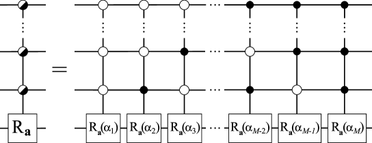
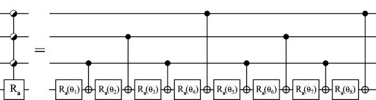
Figure 2 reviews a construction for consisting of CNOT gates and one-qubit -rotations. The case is shown. In the case of a general , the gate sequence may be constructed from the sequence for by replacing the position of the control in the rightmost CNOT gate to the new controlled qubit and repeating the obtained sequence twice for suitable rotation angles . The operational principle of the gate sequence requires that . However, this limitation can be circumvented by introducing one-qubit basis changing gates on the both side of the gate.
The angles can be obtained from using the equation
| (3) |
where and stand for the binary code and binary reflected Gray code representations of the integer , respectively. In actuality, the position of the controls of the CNOT gates in Fig. 2 may be chosen in many different ways which results in replacing in Eq. (3) by another cyclic Gray code Savage (1997). Additionally, a horizontally mirrored version of the gate sequence in Fig. 2 also qualifies to simulate the uniformly controlled rotation.
III State preparation
We are looking for a gate sequence corresponding to a matrix such that for given vectors and . The problem may be reduced to the problem of finding a matrix which takes an arbitrary vector to some fixed vector , since then we may take and such that and, hence, , where the dagger denotes the Hermitian conjugate. For convenience, we take the fixed vector to be the first basis vector .
Our algorithm for transforming into works as follows:
-
•
First we equalize the phases using a cascade of uniformly controlled -rotations , rendering the vector real up to the global phase : .
-
•
Then we rotate the real state vector into the direction of using a similar sequence of uniformly controlled -rotations , thus achieving our goal.
The first step can be readily accomplished using a general diagonal -qubit quantum gate first considered in Ref. Bullock and Markov (2004). It is efficiently produced by a sequence of uniformly controlled -rotations as
| (4) |
where the gate equalizes the phases of the elements connected through the qubit . The rotation angles , the elements of , are found to be
| (5) |
where and .
Next we apply a uniformly controlled -rotation with angles . This has the effect of zeroing the elements of the vector that correspond to the states standing for bit value one in the qubit :
| (6) |
where . In effect we have zeroed the last qubit of the register. This procedure can be repeated on the remaining nonzero elements, until we reach .
Employing the above steps one obtains the desired decomposition
| (7) |
The product of non-commuting matrices in Eq. (7) is to be taken from left to right. Here, to eliminate the remaining global phase one could apply a phase gate. After solving the recursion, the rotation angles in Eq. (7) are found to acquire the values
| (8) |
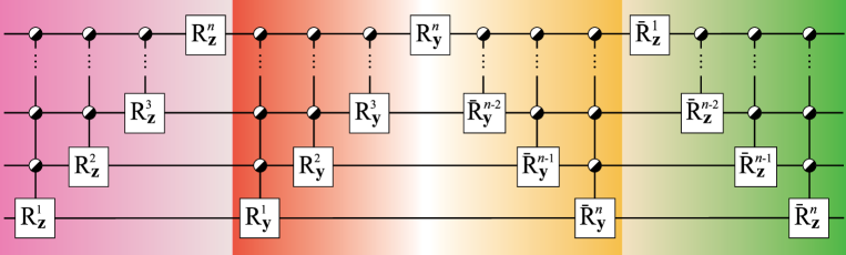
where and . Fig. 3 shows the quantum circuit corresponding to Eq. (7). The resulting gate sequence is slightly simplified by noting that uniformly controlled -rotations, being diagonal, can always be commuted through the control bits of another uniformly controlled gate. Hence, uniformly controlled and rotations acting on the same set of qubits can be commuted next to each other, whereby we can cancel one CNOT from each gate by mirroring the gate.
To transform the state to we need to construct two circuits; the first one takes to and the second one to . Since the uniformly -fold controlled rotation may be constructed from CNOT gates and one-qubit rotations, the entire state preparation circuit requires CNOT gates and one-qubit rotations.
IV Conclusion
In conclusions, we have shown how to construct a general state preparation circuit using a sequence of uniformly controlled rotations. The resulting gate sequence of CNOT gates and one-qubit elementary rotations establishes a new upper bound for the complexity of the transformation. By counting the degrees of freedom of the problem, we find a lower bound of for the number of one-qubit elementary rotations. This implies the lower bound for the number of CNOT gates.
Provided that the initial or final state coincides with some basis vector only half of the CNOT and one-qubit rotation gates are needed. In other special cases some simplifications to the gate sequence also occur. We have also introduced a closed-form scheme for determining the rotation angles in such way that an arbitrary state of the quantum register transforms into desired state.
The gate count is small compared to the incomplete QR decomposition which takes approximately CNOT gates to transform and thus for the whole transformation. It is still an open question if the transformation could be done more directly, i.e., merging some of the consecutive gates together and finding efficient gate array for implementing them. This would reduce the number of elementary gates needed.
Acknowledgements.
This research is supported by the Academy of Finland through the project “Quantum Computation” (No. 206457). MM thanks the Foundation of Technology (Finland), JJV the Nokia Foundation, MM and VB the Finnish Cultural Foundation, and MMS the Japan Society for the Promotion of Science for financial support. Sami Virtanen is acknowledged for stimulating discussions.References
- Nielsen and Chuang (2000) M. A. Nielsen and I. L. Chuang, Quantum Computation and Quantum Information (Cambridge University Press, 2000).
- Vartiainen et al. (2004) J. J. Vartiainen, M. Möttönen, and M. M. Salomaa (2004), eprint quant-ph/0312218.
- Mikko Möttönen et al. (2004) M. Mikko Möttönen, J. J. Vartiainen, V. Bergholm, and M. M. Salomaa (2004), eprint quant-ph/0404089.
- Shende et al. (2004) V. V. Shende, S. S. Bullock, and I. L. Markov (2004), eprint quant-ph/0406176.
- Shende and Markov (2004) V. V. Shende and I. L. Markov (2004), eprint quant-ph/0401162.
- Shende et al. (2003) V. V. Shende, I. L. Markov, and S. S. Bullock (2003), eprint quant-ph/0308033.
- Knill (1995) E. Knill (1995), eprint quant-ph/9508006.
- Savage (1997) C. Savage, SIAM Rev. 39, 605 (1997).
- Bullock and Markov (2004) S. S. Bullock and I. L. Markov, Quant. Inf. and Comp. 4, 27 (2004).