Realization of a photonic CNOT gate sufficient for quantum computation
Abstract
We report the first experimental demonstration of a quantum controlled-NOT gate for different photons, which is classically feed-forwardable. In the experiment, we achieved this goal with the use only of linear optics, an entangled ancillary pair of photons and post-selection. The techniques developed in our experiment will be of significant importance for quantum information processing with linear optics.
Polarization-encoded qubits are well suited for information transmission in Quantum Information Processing (QIP)bouwmeester00a . In recent years, the polarization state of single photons has been used to experimentally demonstrate quantum dense coding mattle96 , quantum teleportation dik97 and quantum cryptography thomas00 ; naik00 ; gisin01 . However, due to the difficulty of achieving quantum logic operations between independent photons, the application of photon states has been limited primarily to the field of quantum communication. More precisely, the two-qubit gates suitable for quantum computation generically require strong interactions between individual photons, implying the need for massive, reversible non-linearities well beyond those presently available for photons, as opposed to other physical systems Schmidtkaler03 .
Remarkably, Knill, Laflamme and Milburn knill01 found a way to circumvent this problem and implement efficient quantum computation using only linear optics, photo-detectors and single-photon sources. In effect they showed that measurement induced nonlinearity was sufficient to obtain efficient quantum computation.
The logic schemes KLM proposed were not, however, economical in their use of optical components or ancillary photons. Various groups have been working on reducing the complexity of these gates while improving their theoretical efficiency (see e.g. Koashi et al. koashi01 ). In an exciting recent development, Nielsen nielsen04 has shown that efficient linear optical quantum computation is in fact possible without the elaborate teleportation and Z-measurement error correction steps in KLM. This is achieved by creation of linear optical versions of Raussendorf and Briegel’s raussendorf cluster states. Nielsen’s method works for any non-trivial linear optical gate which succeeds with finite probability, but which, when it fails, effects a measurement in the computational basis.
A crucial requirement of both KLM’s and Nielsen’s constructions is classical feed-forwardability. Specifically, it must be in principle possible to detect when the gate has succeeded by measurement of ancilla photons in some appropriate state. This information can then be fed-forward in such a way as to condition future operations on the photon modes.
Recently fran03 ; sanaka02 ; obrien03 destructive linear optical gate operations have been realized. As they necessarily destroy the output state, such schemes are not classically feed-forwardable. In the present paper we report the first realization of a CNOT gate which operates on two polarization qubits carried by independent photons and that satisfies the feed-forwardability criterion. Moreover, when combined with single qubit Hadamard rotations to perform a controlled-sign gate (so as to build the cluster states of raussendorf via Nielsen’s method) this gate also satisfies the criterion that when it fails the qubits can be projected out in the computational basis.
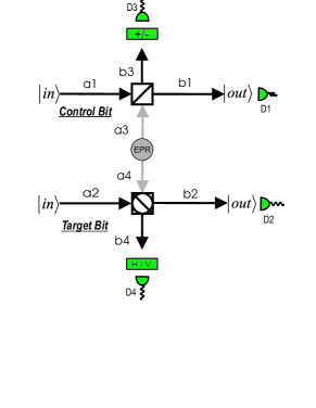
A CNOT gate flips the second (target) bit if and only if the first one (control) has the logical value 1 and the control bit remains unaffected. The scheme we use to achieve the CNOT gate was first proposed in fran01b by Franson et al. and is shown in Fig.1. This scheme performs a CNOT operation on the input photons in spatial modes and ; the output qubits are contained in spatial modes and . The ancilla photons in the spatial modes and are in the maximally entangled Bell state
| (1) |
In the following H (an horizontally polarized photon) and V (a vertically polarized one) will denote our logical 0, 1. The scheme works in those cases where one and only one photon is found in each of the modes ; when both photons are H polarized no further transformation is necessary on the output state (usually this is referred to as passive operation). The scheme combines two simpler gates, namely the destructive CNOT and the quantum encoder. The first gate can be seen in the lower part of the Fig.1 and is constituted by a polarizing beam splitter (PBS2) rotated by (the rotation is represented by the circle drawn inside the symbol of the PBS), which works as a destructive CNOT gate on the polarization qubits, as was experimentally demonstrated in fran01b . The upper part, comprising the entangled state and the PBS1, is meant to encode the control bit in the two channels and . The photons in the spatial modes and are in the maximally entangled Bell state 1
Thanks to the behaviour of our Polarizing Beam Splitter, that transmits horizontally polarized photons and reflects vertically polarized ones, the successful detection at the port of the state (the symbols stand for and ) post-selects the following transformation of the arbitrarily input state in
, thus we have the control bit encoded in and in , the photon in will be the control input to the destructive CNOT gate, and will thus be destroyed, while the second photon in b1 will be the output control qubit.
For the gate to work properly, we want the most general input state
to be converted to the output state
Let us consider first the case where the control photon is in the logical zero (H polarization state). The control photon will then travel undisturbed through the PBS, arriving in the spatial mode . As required, the output photon is H polarized. In order for the scheme to work a photon needs to arrive also at the detector in : given the input photon already in the mode , this additional photon comes necessarily from the EPR pair, and is H polarized as it is transmitted by the PBS1. We know that the photons in and are correlated (1), so the photon in is also in the horizontal polarization. Taking into account the rotation of the polarization on the paths operated by the half-wave plates, the input in the PBS2 will then be the state for a target photon H (V) polarized. This state will give rise, with a probability of , to the state where two photons go through the PBS2 which, after the additional rotation of the polarization, and the subsequent change to the H/V basis (where the measurement will be performed) acquires the form . The expected result in the mode H(V) for the case where the photon in is horizontally polarized. We can see in a similar way that the gate works also for the cases where the control photon is vertically polarized, or is polarized at .
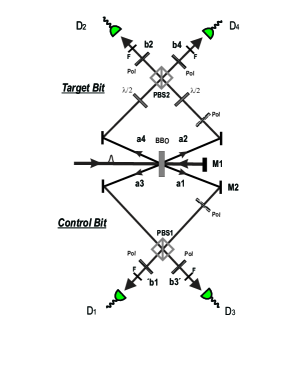
Our experimental setup is shown in Fig.2. In order to produce the entangled pair of ancilla photons in modes and , we use a type II Spontaneous Parametric Down Conversion (SPDC) process; this pair is responsible for the transmission of the quantum part of the information. We also need to produce the two input qubits in the modes and to feed into the gate. In our setup these input qubits are another SPDC pair, where photon number entanglement is used and two photons are simultaneously produced; the polarization entanglement is destroyed by letting the photons pass through appropriate polarizers. Thanks to these polarization filters, and to appropriate half-wave plates, any desired two-qubits input state can be prepared.
An ultraviolet pulsed laser, centered at a wavelength of 398nm, with pulse duration 200fs and a repetition rate of 76MH, impinges on a BBO crystal kwiat95a producing probabilistically the first pair in the spatial modes and : these two photons are fed into the gate as the input qubits. The UV laser is then reflected back by the mirror M1 and, passing through the crystal a second time, produces the entangled ancilla pair in spatial modes and . Half-wave plates and non-linear crystals in the paths provide the necessary birefringence compensation, and the same half-wave plates are used to adjust the phase between the down converted photons (i.e. to produce the state ) and to implement the CNOT gate.
We then superpose the two photons at Alice’s (Bob’s) side in the modes at a polarizing beam splitter PBS1 (PBS2). Moving the mirror M1, mounted on a motorized translation stage, allows to change the arrival time to make the photons as indistinguishable as possible. A further degree of freedom is afforded by the mirror M2, whose movement on a micrometrical translation stage corrects slight asymmetries in the arms of the set up. The indistinguishability between the overlapping photons is improved by introducing narrow bandwidth (3nm) spectral filters at the outputs of the PBSs and monitoring the outgoing photons by fiber-coupled detectors. The single-mode fiber couplers guarantee good spatial overlap of the detected photons; the narrow bandwidth filters stretch the coherence time to about 700fs - substantially larger than the pump pulse duration marek95 . The temporal and spatial filtering process effectively erases any possibility of distinguishing the photon-pairs and therefore leads to interference.
The scheme we have described allows the output photons to travel freely in space, so that they may be further used in quantum communication protocols, and this is achieved by detecting one and only one photon in modes and . The fact that we do not yet have single-photon detectors for this wavelength at our disposal actually forces us to implement a four-fold coincidence detection to confirm that photons actually arrive in the output modes and .
So far, we have analyzed only the ideal case where exactly one pair is produced at each passage of the UV light beam through the BBO crystal. Let us see now how the two-pair events are going to influence the outcomes. It is easy to see that our gate cuts out those unwanted cases where two pairs are produced in the spatial modes : if the two photons in the spatial mode are both horizontally or vertically polarized, either two or no photons will arrive at the detector D3. The alternative case is that the pairs in each spatial mode have two photons that are in opposite polarization states; this could produce either two or no photons in paths and . It is thus proved that no four-fold event may occur from an event of this kind.
Unluckily, this kind of noise is present for superposed qubits; however, it may be easily measured and eliminated covering the spatial modes and and measuring the four-fold coincidences. Anyway, we note that the noise is not intrinsic in the setup and is only due to practical drawbacks. Indeed, an unbalancing method like the one used in pan03a would allow one to increase the signal to noise ratio to any desired value.
One more detail that should be addressed here is the problem of birefringence. Each PBS introduces a small shift between the H and V components, thus deteriorating the overlap of the photon wavepackets. This birefringence is responsible for the presence of unwanted terms at the output state. The non-linear crystals put on the optical path are able to compensate for this as well, as remarked elsewhere pan03b .
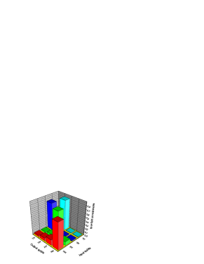
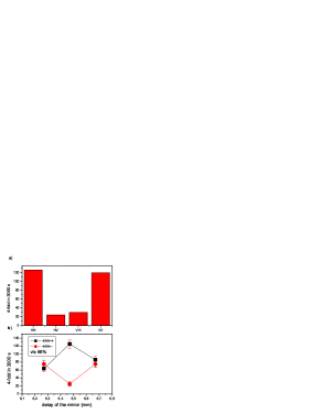
To experimentally demonstrate that the gate works, we first verify that we obtain the desired CNOT (appropriately conditioned) for the input qubits in states HH, HV, VH and VV. In Fig. 3 we compare the count rates of all 16 possible combinations. We see indeed that the gate is working properly in this basis. Having verified this, we prove that the gate also works for a superposition of states. The special case where the control input is a polarized photon and the target qubit is a H photon is very interesting: we expect that the state evolves into the maximally entangled state . This shows the reason why CNOT gates are so important: they can transform separable states into entangled states and vice versa. We input the state ; first we measure the count rates of the 4 combinations of the output polarization (HH,..,VV) and observe that the contributions from the terms HV and VH are negligible with a fidelity of .
Then we prove that the output state is in a coherent superposition, which is done by a further polarization measurement. Going to the linear polarization basis a Ou-Hong-Mandel interference measurement is possible; this is shown in fig.4.
To sum up, the above demonstrated realization of a feed-forwardable photonic CNOT gate uses only linear optics and entanglement. The non-linearities required in such an interaction are obtained through projective measurement of the ancilla pair. Our result is an important progress in the direction of the realization of a quantum computer. The price we pay for a non-destructive scheme is the higher experimental sophistication, particularly the necessity to use high precision timing and coincidence techniques.
This work was supported by the European Commission, contract numbers ERBFMRXCT960087 and IST-1999-10033 and by the Austrian Science Foundation (FWF), project number S6506.
References
- 1 D. Bouwmeester, A. Ekert & A.Zeilinger,A. The Physics of Quantum Information, Springer(Berlin), (2000)
- 2 K. Mattle, H.Weinfurter, P. G. Kwiat & A. Zeilinger. Phys. Rev. Lett. 76, 4656 (1996).
- 3 D. Bouwmeester et al. Nature 390, 575 (1997).
- 4 T. Jennewein et al. Phys. Rev. Lett. 84, 4729 (2000);
- 5 D. S. Naik, et al., Phys.Rev.Lett.84, 4733 (2000);
- 6 N. Gisin, G. Ribordy, W. Tittel, & H. Zbinden. Rev of Mod. Phys.74,145 (2002)
- 7 F. Schmidt-Kaler et al., Nature 422, 408(2003) and references therein.
- 8 E. Knill, R. Laflamme & G. J. Milburn G. J. Nature 409, 46 (2001).
- 9 M. Koashi, T. Yamamoto & N. Imoto. Phys. Rev. A 63, 030301 (2001)
- 10 M. A. Nielsen, quant-ph/0402005
- 11 R. Raussendorf & H. Briegel, Phys. Rev. Lett.,86 5188 (2001).
- 12 T.B. Pittman, M.J. Fitch, B.C. Jacobs & J. D. Franson. Phys. Rev. A, 68, 032316 (2003)
- 13 K. Sanaka, K. Kawahara & T. Kuga. Phys. Rev. A 66 040301, (2002)
- 14 J. L. O’Brien et al. Nature, 426, 264 (2003)
- 15 T.B. Pittman, B.C. Jacobs & J.D. Franson Phys.Rev.Lett., 88, 257902 (2002)
- 16 P. G. Kwiat et al. Phys.Rev.Lett. 75, 4337 (1995).
- 17 M. Zukowski, A. Zeilinger & H. Weinfurter. Ann. NY Acad. Sci. 91, 755 (1995).
- 18 J.-W Pan et al. Nature 421, 721 (2003)
- 19 J.-W. Pan et al. Nature 423, 417 (2003)