Nonmaximally-entangled-state quantum photolithography
Abstract
Many previous works on quantum photolithography are based on maximally-entangled states (MES). In this paper, we generalize the MES quantum photolithography to the case where two light beams share a -photon nonmaximally-entangled state. we investigate the correlations between quantum entanglement and quantum photolithography. It is shown that for nonlocal entanglement between the two light beams the amplitude of the deposition rate can be changed through varying the degree of entanglement described by an entanglement angle while the resolution remains unchanged, and found that for local entanglement between the two light beams the effective Rayleigh resolution of quantum photolithography can be resonantly enhanced.
PACS number(s): 42.50.Dv, 42.25.Hz, 85.40.Hp
I Introduction
Recently, much attention has been paid to quantum photolithography r1 ; r2 ; r3 ; r3' due to the possibility of beating the classical Rayleigh diffraction limit through using on quantum entanglement between two used light beams. Optical lithography is a widely used printing method which has been the primary tool of the semiconductor industry for transferring circuit images onto substrates to produce smaller and smaller processors. In this process, light is used to etch a substrate and the exposed or unexposed areas on the substrate define patterns. The resolution of images transferred by using classical light beams is restricted to the Rayleigh diffraction limit , being the wavelength of the light, hence one can achieve a resolution only comparable to the wave length of the light used in classical optical lithography r4 ; r5 ; r6 . In Ref. r3 , Agedi and coworkers introduced a procedure called quantum lithography in one dimension that predicts an increase in resolution beyond the diffraction limit due to quantum entanglement between two light beams, and demonstrate a quantum lithography method to improve the resolution by a factor in contrast to classical one, using -photon maximal entangled state (MES) r7 . The Maryland group r2 completed a proof-of-principle experimental demonstration of quantum lithography by using two-photon entangled state generated via a specially designed spontaneous parametric down-conversion. The increase in resolution makes quantum lithography a potentially useful tool to produce smaller computer chips in nanotechnology. Then the one-dimensional quantum lithography method was generalized to the two-dimensional case r8 and entangled binomial states r9 . Since the number of elements writable on a surface scales inverse quadratically with the minimum feature dimension, this improvement is an important advance. The purpose of the present paper is to generalize the MES quantum lithography to the case where two light beams share a -photon nonmaximally-entangled state (NMES), and investigate properties of the deposition rate for general patterns in one dimension.
This paper is organized as follows. In Sec. II, we introduce the NMES quantum lithography method after briefly recalling the MES quantum lithography method. In Sec. III we discuss pattern engineering in one dimension. Finally, we summarize our results in Sec. IV.
II NMES quantum photolithography
The quantum photolithographic process is based on the multi-photon absorption process on a substrate. The character parameter of the optical lithography is the minimal resolvable feature size which, according to Rayleigh criterion, occurs at a spacing corresponding to the distance between an intensity maximum and an adjacent intensity minimum r9 , or optical resolution which may denote the minimal distance between two nearby points that can still be resolved with microscopy or the minimal distance separating two points that are printed using lithography. For a -photon state the resolution is determined by the absorption rate at the imagine surface which is proportional the expectation value of the dosing operator
| (1) |
where the dosing operator is defined by
| (2) |
with the superposition mode operator and its adjoint . If a substrate is exposed for a time to the light source, the exposure function gives an exposure pattern.
Before going into the NMES lithography, let us briefly review the MES quantum lithography presented in Ref r3 . Consider two counterpropagating light beams and cross each other at the surface of a photosensitive substrate. They have a relative phase difference with the optical wave number and is the lateral dimension on the substrate to describe the position where the two beams meet. For the -photon maximally-entangled number state of the two light beams
| (3) |
from Eqs. (1) and (2) one can get the following deposition rate
| (4) |
which indicates that a shift of will displace times. Hence, the -photon MES (1) produces an effective Rayleigh resolution given by
| (5) |
which increases the resolution by a factor in contrast to the classical diffraction limit .
Now we consider the quantum lithography with a -photon NMES given by
| (6) |
where measures the entanglement of the state, it changes from (no entanglement) to (maximal entanglement).
In what follows, we consider the influence of quantum entanglement for the two cases of nonlocal and local entanglement, respectively.
Case 1. Nonlocal entanglement. In this case, the entangling angle of the two light beams is independent of the position where the two beams meet, then is irrelevant to the phase difference in the NMES (6). From the expression of the deposition rate (7) we can see that the amplitude of the deposition function increases with the degree of entanglement. Hence one can manipulate and control the amplitude of the deposition rate through varying the quantum entanglement between the two light beams.
Case 2. Local entanglement. In this case, the entangling angle of the two light beams is dependent of the position where the two beams meet, then is relevant to the phase difference in the NMES (6). From Eq. (7) we can see that this type of phase relevance, which is induced by the local entanglement, affects the period of the deposition function. It is the period of the deposition function that determines the resolution of the quantum photolithography. Hence, the local entanglement between the two light beams can improve the resolution. In particular, if we suppose that the entanglement angle changes with variation of the phase according to the resonant relation with being positive integers, then the deposition function (7) becomes
| (8) |
which leads to the following resolution
| (9) |
which indicates that resonant change of the entanglement angle of the -photon NMES enhances the resolution by a factor in contrast to the case of the -photon MES. Therefore, one can improve the resolution through resonantly changing the entanglement angle of the -photon NMES.
In optical lithography, one usually wishes that produced patterns are uniform. However, the second and third terms on the right-hand side of Eq. (8) have different periods with respect to the phase . In general superpositions of periodic functions with different modulation periods produces so-called collapse-and-revival phenomena which appear in laser-atom interactions r11 ; r12 . These collapses and revivals produce are non-uniform patterns. This non-uniform pattern problems can be removed through choosing specific values of in Eq. (8). If we set , the deposition function becomes
| (10) |
which leads to the following resolution
| (11) |
which implies that uniform patterns can be produced and the resolution is doubled with respect to the MES quantum lithography.
III Pattern engineering in one dimension
In this section, we show how to manipulate and control patterns in one dimension using the -photon NMES and superposition principle in quantum mechanics. In order to engineer arbitrary one-dimensional paterns, we consider a more general -photon NMES
| (12) | |||||
which is an extension of the -photon NMES given by Eq. (6) and reduces to Eq. (6) when and . In order to obtain the deposition rate corresponding to the -photon NMES (12), we have to calculate the matrix elements of the dosing operator
| (13) |
which is given by
| (14) | |||||
where we have used the symbol .
Then the expectation value of the dosing operator with respect to the general -photon NMES (12) can be obtained by taking the condition in Eq. (12)
| (15) |
In particular, when , the deposition rate (15) becomes
| (16) |
Thus, we recover the deposition rate for the case of the -photon MES r5 .
One important point to be emphasized is that based on the -photon NMES (12) one can design various types of patterns on a substrate through building various different kinds of superposition states of the -photon NMES (12). We here consider the pseudo-Fourier method r7 where one uses a general superposition state with different photon numbers and a fixed distribution over two modes
| (17) |
where the basic state is defined by (12) through replacing with ,it is a -photon NMES, and is an arbitrary coefficients. Hence, the state is a superposition state of states with different total photon numbers in each branch.
Since , branches with different photon numbers and do not exhibit interference when we calculate the -photon deposition rate of the superposition state (17) which can be written as
| (18) |
Making use of Eqs. (12) to (15), from (18) we obtain
| (19) |
where is given by Eq. (15) with replacing by . Eq. (19) implies that the deposition rate of the superposition state (17) depends on only the module of the superposition coefficients , and it is independent of the phase of .
Using the expression of exposure pattern , from Eqs. (15) and (19) we find that
| (20) |
which indicates that the exposure pattern induced by the superposition state (17) is determined by the module of the superposition coefficients , the entanglement angle , and the relative phase .
From Eq. (20) it is easy to understand the role of quantum entanglement in quantum photolithography. In fact, from Eq. (20) we can see that varying of the entanglement angle is equivalent to rescaling time parameter or/and the module of the superposition coefficient for the case of nonlocal entanglement where the entanglement angle is independent of the associated phase difference . In particular, when , Eq. (20) reduces to the expression of exposure pattern of the MES case r7
| (21) |
For the case of nonlocal entanglement the expression of exposure pattern (20) can be written as the sum of a general uniform background exposure of the substrate and a standard truncated Fourier series
| (22) |
where is the uniform background penalty exposure rate
| (23) |
and the expanding coefficients are determined by the module of the superposition coefficients , the entanglement angle , and the relative phase with the following expressions
| (24) |
From Eqs. (22), (23), and (24) we can see that quantum entanglement between two light beams dos not change the background penalty exposure rate but it controls the amplitudes of all Fourier components.
It is well known that any sufficiently well-behaved periodic function can be written as an infinite Fourier series. However, when we create patterns with the pseudo-Fourier lithography method, we do not have access to every component of the Fourier expansion, since this would involve an infinite number of photons . This means that we can only employ truncated Fourier series, and these can merely approximate arbitrary patterns.
The Fourier expansion has the nice property that when a series is truncated at , the remaining terms still give the best Fourier expansion of the function up to . In other words, the coefficients of a truncated Fourier series are equal to the first coefficients of a full Fourier series.
As an example, in what follows we use the pseudo-Fourier method to simulate a pattern generated by the following test function
| (25) |
which can be expanded as a Fourier series
| (26) |
Comparing Eq. (26) with (22) and using (24) we find the subsidiary phase and the superposition coefficients in Eqs. (12) and (17) to be
| (27) | |||||
| (28) |
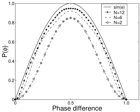
Substituting Eqs. (27) and (28) into Eq. (17), one can obtain the superposition state to realize the pattern of the test function given by Eq. (25). And from (27), (28) and (17) we can see that the superposition state consists of even-number-photon NMES like (12), and only the module of the superposition coefficients affect the deposition rate of quantum photolithography. In Figure 1 we have simulated the test pattern (25) by using the superposition state given by Eq. (24) for , , and cases, respectively. From Figure 1 we can see that the calculated patterns are in good agreement with the test pattern as shown by the solid curve, and the larger the value of is, the better the effect of the simulation.
IV Concluding remarks
In conclusion we have generalized the -photon MES quantum photolithography to the -photon NMES case, and investigated the correlations between quantum entanglement and quantum photolithography. It has been found that quantum photolithography can be manipulated and controlled through varying quantum entanglement between two applied light beams. Especially, for the nonlocal entanglement case, we have showed that the amplitude of the deposition function increases with the degree of entanglement. Hence one can manipulate and control the amplitude of the deposition rate through varying the quantum entanglement between the two light beams while the resolution of quantum lithography remains unchanged. And for the local entanglement case, we have found that the local entanglement between the two light beams can enhance the effective Rayleigh resolution of quantum photolithography. However, it would be challenging to create locally entangled states.
Acknowledgements.
This work is supported by the National Fundamental Research Program Grant No. 2001CB309310, the National Natural Science Foundation Grant Nos. 90203018 and 10075018, the State Education Ministry of China, the Educational Committee of Hunan Province, and the Innovation Funds from Chinese Academy of Sciences via the Institute of Theoretical Physics, Academia, Sinica.References
- (1) Rathe U V and Scully M O, 1995 Lett. Math. Phys. 34 297
- (2) D’Angelo M, Chekhova M V, and Shih Y 2001 Phys. Rev. Lett. 87 013602
- (3) Boto A N, Kok P, Abrams D S, Braunstein S L, Williams C P, and Dowling J P 2000 Phys. Rev. Lett. 85, 2733
- (4) Lugiato L A, Gatti A and Brambilla E 2002 J. Opt. B: Quantum Semiclass. Opt. 4 S1
- (5) Brück S R J et al., 1998 Microelectron. Eng. 42 145
- (6) Mack C A 1996 Opt. Photonics News 7 29
- (7) Manuscripure M and Liang R 2000 Opt. Photonics News 11 36
- (8) Kok P, Boto A N, Abrams D S, Williams C P, Braunstein S L, and Dowling J P 2001 Phys. Rev. A 63 063407
- (9) Björk G, Sanchez-Soto L L and Säderholm J 2001 Phys. Rev. A 64 013811
- (10) Björk G, Sanchez-Soto L L and Säderholm J 2001 Phys. Rev. Lett. 86 4516
- (11) Rayleigh L 1879 Philos. Mag. 8 261; Born M and Wolf E 1980 Principles of Optics (Pergamon Press. New York. 1980), 6th ed., Sec. 7.6.3.
- (12) Narozhny N B 1981 Phys. Rev. A 23 236
- (13) Rempe G, Walther H and Klein N 1987 Phys. Rev. Lett. 58 353