Experimental demonstration of entanglement assisted coding
using a two-mode squeezed vacuum state
Abstract
We have experimentally realized the scheme initially proposed as quantum dense coding with continuous variables [Ban, J. Opt. B 1, L9 (1999), and Braunstein and Kimble, Phys. Rev. A61, 042302 (2000)]. In our experiment, a pair of EPR (Einstein-Podolski-Rosen) beams is generated from two independent squeezed vacua. After adding two-quadrature signal to one of the EPR beams, two squeezed beams that contain the signal were recovered. Although our squeezing level is not sufficient to demonstrate the channel capacity gain over the Holevo limit of a single-mode channel without entanglement, our channel is superior to conventional channels such as coherent and squeezing channels. In addition, optical addition and subtraction processes demonstrated are elementary operations of universal quantum information processing on continuous variables.
pacs:
03.67.Hk, 42.50.DvI Introduction
The entanglement of the EPR beams generated by superimposing two independent squeezed beams FK98 is utilized in continuous-variable (CV) quantum information experiments, such as quantum teleportation FK98 ; ZGCLK03 ; BTBSRBSL03 and quantum dense coding Ban99 ; Ban00 ; BK00 ; LJZXP02 ; RH02 . The latter scheme utilizes this entanglement to enhance the channel capacity of a communications channel by reducing the vacuum noises in both of two quadratures of a signal. This can also be applied to sub-shot-noise sensing and cryptography.
The principle of CV dense coding was first demonstrated by Li et al. LJZXP02 in a form somewhat simplified from the original proposal BK00 . They used bright EPR beams and detected the photocurrents directly without any additional local oscillators (LOs) in the scheme they called self homodyning. The simplicity of their scheme can be an advantage for implementation of, e.g., CV quantum cryptography. In terms of channel capacity in the power constrained scenario, however, their scheme cannot be efficient since self homodyning requires the bright carrier component (that plays the role of LO) sent through the channel. This carrier component occupies the major fraction of the limited power in the channel without contributing to the signal. We will return to this point later in the discussion (Section IV).
In this paper, we describe our experiment that is performed in the way initially proposed by Braunstein and Kimble BK00 . Two independent squeezed vacua are used as the EPR source and separate LOs are used in homodyne detection. The necessity of independent LOs makes our setup elaborate, but this allows us broader and more flexible operations on CV SB98a ; SB98b ; LloydBraunstein99 ; GKP01 ; BS02 . In addition, the use of squeezed vacua is valuable in sensing of a system whose state may be disturbed by a bright light probe.
II Principle
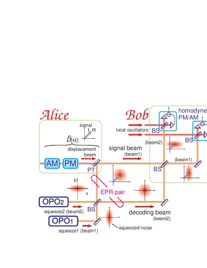
The actual experiment shown in Fig. 1 is carried out using optical sideband modes, although the principle below is described in the carrier mode. The squeezed states show nonclassical correlations between upper and lower sidebands, and the two-quadrature displacement corresponds to the amplitude and phase modulations (AM, PM) of the displacement beam. Homodyne detection converts the amplitudes of two optical sidebands to the photocurrents of the frequency near DC, which is then measured electrically.
The squeezed vacuum is generated by an optical parametric oscillator (OPO) operated below threshold. In our setup, operations of OPO1 and OPO2 are described by
| (1) | |||||
| (2) |
respectively, where () is the squeezing parameter, and are the canonically conjugate operators () for the two orthogonal quadratures in phase space, which we refer to as - and -quadratures. The superscript is for the input field which is assumed to be in the vacuum state, i.e. and .
The output fields from the OPOs are combined by a 50 : 50 beamsplitter to compose a pair of EPR beams. They are described by the operators
| (3) | |||||
| (4) |
When each EPR beam is detected separately, we observe the so-called EPR noise which is larger than the shot noise level.
At Alice’s site, the beam 1 experiences a displacement described by the operator where the complex number represents a two-quadrature signal. This displacement is achieved by using a partially transmitting mirror which reflects the EPR beam with a small loss and adds a small fraction of the displacement beam to realize the displacement by . This beam 1 after displacement is the signal beam that is sent through the channel.
At Bob’s site, the signal beam is combined with the other beam of the EPR pair (the beam 2, the decoding beam) via a 50 : 50 beamsplitter. The resulting output state is a separable product of two displaced squeezed states. They are then detected by two balanced homodyne detectors to extract the signal in - and -quadratures of the beams 1 and 2, respectively. The measurement results exhibit the signal in two quadratures
| (5) |
with variances smaller than the shot noise limit () simultaneously,
| (6) | |||||
by the virtue of the entanglement of EPR beams ().
III Experiment
In our experiment, a Ti:sapphire laser (Coherent Scotland, MBR–110) excited by a 10 W, 532 nm DPSS laser (Coherent, Verdi–10) is used as the source of 1.3 W fundamental wavelength (860 nm). Major fraction (90 %) of the beam is used to generate second harmonic wavelength (430 nm) of 120 mW by a frequency doubler (Coherent Scotland, MBD–200). The second harmonic beam is used to generate two squeezed beams at fundamental wavelength through parametric down-conversion processes (see below). The rest of the fundamental beam is used as a signal (i.e. displacement beam), as LOs for balanced homodyne detection, and also as probe beams for various control purposes.
For optical parametric down-conversion, a 10 mm long potassium niobate (KNbO3) crystal with temperature control for noncritical phase matching is employed as nonlinear optical material PCK92 . It is placed around the beam waist (with a beam radius 20 m) in the cavity composed of four mirrors, two flat and two concave (curvature radius 50 mm) ones, which form a bow-tie configuration with a round-trip length of 500 mm. At the fundamental wavelength the mirrors are highly reflective () excepting the flat output coupler that has a transmittance of . All mirrors are transmissive () at the second harmonic wavelength, and thus the pumping beam is essentially single pass.
The two squeezed beams are superimposed at a 50 : 50 beamsplitter to compose a pair of EPR beams. At Alice, one of them (signal beam) is superimposed at a partially transmitting mirror () with a displacement beam which contains possible AM and PM signals. The signal beam is then decoded at Bob by being superimposed with the decoding beam at another 50 : 50 beamsplitter. Each of the two resultant beams is detected by a balanced homodyne detector using photodiodes with quantum efficiencies of 99.9 % (Hamamatsu, S3590 AR coated at 860 nm).
Each squeezed beam is marked by a probe beam ( 7 W after the flat output coupler) that is taken from the fundamental light source and is injected in parallel to the squeezed beam through one of the high reflectors of the OPO cavity. Each probe beam is phase-modulated at a frequency different from each other (around 55 kHz and 64 kHz). The relative phase to compose the EPR beams is controlled referring this probe beam. Similarly, other interference phases (to superimpose the displacement beam, to decode at Bob, and to detect by balanced homodyne detectors) are all controlled, either through DC interference or via demodulating the modulation applied to the probe beam. These control loops keep the whole optical system to proper operating points during measurements. (Some of them may be scanned to investigate the phase dependences.)
IV Results and discussion
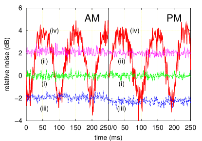
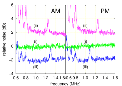
The experimental results are shown in Figs. 2 and 3. The former shows the noise power around 1.1 MHz in the time domain and the latter shows the noise power spectra in the frequency domain, both in two quadratures. (See their captions for the measurement parameters.) As can be seen in the figures, the level of squeezing is about 2.0 dB () in this experiment.
Fig. 2 shows various noise levels in each quadrature; those are the shot noise, the EPR noise [the variances of the operators given in Eqs. (3) and (4)], and the recovered squeezed noises with LO scanning and with LO locked [Eq. (6)]. It can be seen that the EPR noise is larger than the shot noise and also is phase independent. This EPR noise can be canceled by combining with the other EPR beam (decoding beam), resulting in two separable squeezed states. It is clearly confirmed by the asymmetrically oscillating curves with steep dips when the LO phases are scanned. When the LO phases are locked to the minima, the noise levels of both quadratures simultaneously stay lower than that of the shot noise (the vacuum state).
Fig. 3 shows essentially the same information as Fig. 2 in the frequency domain, with simulated AM and PM signals at 1.3 MHz and 1.1 MHz, respectively. The two simultaneously added signals are clearly separated in the outputs of two homodyne detectors. Obviously the signals that were buried in the vacuum noise become apparent after the optical subtraction process.
The amount of information that can be transmitted by a dense coding channel with the given level of squeezing and the average signal photon number is given by BK00 ; RH02
| (7) |
Since squeezing requires a finite photon number of , the average photon number in the signal beam is given by
| (8) |
In evaluating the capacities of various CV channels, this must be fixed, as was assumed in Refs. [BK00, ; RH02, ]. We refer to this condition as the power constrained scenario.
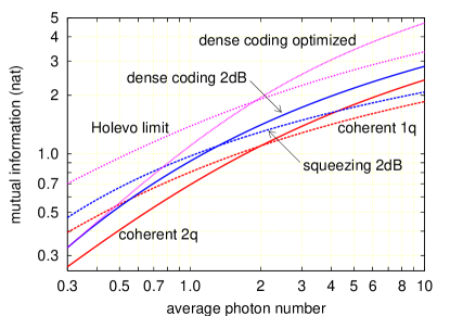
Fig. 4 depicts the amounts of information transmitted by various channels (see the caption for details) in the power constrained scenario, derived in literature such as Refs. [BK00, ; RH02, ] and references therein. The dense coding channel is always superior to a conventional coherent state channel using two quadratures. With the present level of squeezing, about 2.0 dB, our dense coding channel has the capability of exceeding the single quadrature channel using the same level of squeezing under the condition of . This condition on can be further reduced by the use of improved squeezing.
The ultimate performance of dense coding, optimized assuming that an arbitrary level of squeezing is available, is also shown in Fig. 4. As can be seen in the figure, it exceeds the (yet-to-be-achieved) classical limit of a bosonic channel capacity without entanglement (the Holevo limit of a single-mode bosonic channel) for with squeezing level of 6.78 dB BK00 . The minimum squeezing level required to beat the classical limit for a larger is 4.34 dB, i.e. (see Ref. [RH02, ]). When such a level of squeezing becomes available, our scheme has the potential of achieving this, i.e., of realizing ‘true’ quantum dense coding as is discussed in the original proposals Ban99 ; BK00 .
This should be contrasted with the experiment in Ref. [LJZXP02, ], which inevitably requires a bright component in the channel for self homodyning. This bright component must be taken into account as an additional term in Eq. (8) for a comparison in the power constrained scenario. Then the information gain attained by dense coding will be diminished. To maximize the channel capacity within a fixed power in the channel, it is necessary to prepare separate local oscillators at the receiver and to preserve the photons in the channel for signals.
Our experiment also requires further improvements, in addition to the squeezing level, to realize true quantum dense coding. The excess noise at antisqueezing [peaks of plot (iv) in Fig. 2] contains extra photons (assuming Gaussian noise, see Ref. [RH02, ]) of where and are the squeezing and antisqueezing levels, respectively. From the uncertainty principle is required and in ideal cases can be zero. But there are often extra photons to be added to Eq. (8) in actual experiments, for example in our present experiment. Such extra photons increases the squeezing level required to surpass the classical limit from the minimum mentioned above. Furthermore, the probe beam to control relative phases among the beams is present in the signal beam. This must be removed before the transmission channel (by using a different wavelength or a different polarization), and the local ocillators in homodyne detection must be controlled referring to the signal itself. These are, however, technical rather than principal issues.
V Conclusion
We demonstrate the entanglement assisted coding using a two-mode squeezed vacuum state, whose capacity exceeds those of conventional coherent state channels and of squeezed state homodyne channel. The scheme is useful, even in the present form, for sensing with weak optical power. When sufficiently high level of squeezing become available, quantum dense coding using CV can be realized as the natural extension of the present scheme. From the technical aspect, basic operations on CV such as the displacement of an EPR beam and the recovery of separable squeezed states from the EPR beams are demonstrated.
Acknowledgements.
The authors are grateful to Dr. Ban, Dr. Aoki, Dr. Fujiwara, Dr. Takeoka, Mr. Takei, Mr. Hiraoka, and Mr. Yonezawa for their help and discussions.References
- (1) A. Furusawa, J.L. Sørensen, S.L. Braunstein, C.A. Fuchs, H.J. Kimble, and E.S. Polzik, “Unconditional Quantum Teleportation,” Science 282, 706 (1998).
- (2) T.C. Zhang, K.W. Goh, C.W. Chou, P. Lodahl, H.J. Kimble, “Quantum teleportation of light beams,” Phys. Rev. A67, 033802 (2003).
- (3) W.P. Bowen, N. Treps, B.C. Buchler, R. Schnabel, T.C. Ralph, H.-A. Bachor, T. Symul, P.K. Lam, “Experimental investigation of continuous variable quantum teleportation,” Phys. Rev. A67, 032302 (2003).
- (4) M. Ban, “Quantum Dense Coding via a Two-mode Squeezed-vacuum State,” J. Opt. B 1, L9 (1999).
- (5) M. Ban, “Information transmission via dense coding in a noisy quantum channel,” Phys. Lett. A 276, 213 (2000).
- (6) S.L. Braunstein and H.J. Kimble, “Dense coding for continuous variables,” Phys. Rev. A61, 042302 (2000).
- (7) X. Li, Q. Pan, J. Jing, J. Zhang, C. Xie, and K. Peng, “Quantum Dense Coding Exploiting a Bright Einstein-Podolsky-Rosen Beam,” Phys. Rev. Lett. 88, 047904 (2002).
- (8) T.C. Ralph and E.H. Huntington, “Unconditional continuous-variable dense coding,” Phys. Rev. A66, 042321 (2002).
- (9) S.L. Braunstein, “Error Correction for Continuous Quantum Variables,” Phys. Rev. Lett. 80, 4084 (1998).
- (10) S.L. Braunstein, “Quantum error correction for communication with linear optics,” Nature (London)394, 47 (1998).
- (11) S. Lloyd and S.L. Braunstein, “Quantum Computation over Continuous Variables,” Phys. Rev. Lett. 82, 1784 (1999).
- (12) D. Gottesman, A. Kitaev, and J. Preskill, “Encoding a qubit in an oscillator,” Phys. Rev. A64, 012310 (2001).
- (13) S.D. Bartlett and B.C. Sanders, “Universal continuous-variable quantum computation: Requirement of optical nonlinearity for photon counting,” Phys. Rev. A65, 042304 (2002).
- (14) E.S. Polzik, J. Carry, and H.J. Kimble, “Atomic Spectroscopy with Squeezed Light for Sensitivity Beyond the Vacuum-State Limit,” Appl. Phys. B55, 279 (1992).