A feasible gate for scalable linear optics quantum computation using polarization optics
Abstract
Knill, Laflamme, and Milburn (KLM) proved that it is possible to build a scalable universal quantum computer using only linear-optics elements and conditional dynamics [Nature (London) 409, 46 (2001)Knill ]. However, the practical realization of the quantum logic gate for the scheme is still technically difficult. A major difficulty is the requirement for sub-wavelength level stabilization of the interlocking interferometers. Following our recent experimental work[Phys. Rev. Lett.92, 017902 (2004)Sanaka2 ], we describe a more feasible scheme to implement the gate that greatly reduces the experimental stability requirements. The scheme uses only polarizing beam splitters and half-wave plates.
Quantum computers promise unprecedented processing power for certain types of problems like factoring products of large prime numbersShor and searching database Grover .We have recently experimentally demonstrated many important features of the nonlinear sign shift (NS) operation in a stable, polarization insensitive configuration for the scalable linear optics quantum computationSanaka2 . In this theoretical work, we show how those NS operations can be used, together with additional linear optical elements, to build up a two qubit logic gate.
One of the most promising systems in which to store and manipulate quantum information is the polarization state or spatial mode of single photons. This is due to the photon’s robustness against decoherence and the ease of which certain necessary operations (i.e., single-qubit operations) can be carried out. However it has been very difficult to perform the necessary two-qubit operations since there is no natural interaction between photons; even when atoms mediate photon-photon interactions through nonlinear optical effects, these effects are usually negligible at the quantum level. Nonlinear optics at the quantum level has been demonstrated in cavity QED experimentsTurchette ; Rauschenbeutel , through quantum interferenceResch , and proposed for systems using electromagnetically-induced transparencyHarris ; Kash and photon-exchange interactionsFranson . In stark contrast to these approaches, Knill, LaFlamme, and Milburn (KLM) showed that effective nonlinear interactions could be implemented using only linear optical elements in conjunction with single-photon sources and conditioning evolution based on successful measurementsKnill . Furthermore, they proved that their scheme could be used, in principle, to build a scalable universal quantum computer. While their two-qubit gate itself is not deterministic, KLM showed that it can be made arbitrarily close to deterministic when used in conjunction with quantum teleportation Gottesman .
In the KLM scheme, the two-qubit gate is achieved by the conditional sign-flip(CS) operation : . Where , show the number of photons in optical mode A and B. The CS gate is constructed by the most fundamental element, so-called nonlinear sign-shift (NS) gates, which performs the transformation: with some probability. Where the kets represents the number of photons in a optical path. CS operation is achieved by placing one NS gate in each arm of a balanced Mach Zehnder interferometer.
Some other types of CS that are not based on the KLM NS gate have also been proposed Knill2 ; Koashi ; Pittman ; Zou ; Hofmann ; Sanaka , however Lund et al. shows that the two-qubit gate using the NS gates is the most resilient with non-ideal ancilla mode production and detectionLund . Ralph et al. simplified the KLM NS gate using non-polarizing beam splitters with unequal reflectivitiesRalph . This considerable flexibility makes it possible to construct the CS gate with much lower effort than original KLM scheme. However the sub-wavelength level stabilization for the whole setup is still essential because the injected photons are spatially superposed with the two arms of Mach Zehnder interferometer and the phase correlation between the arms must be maintained during the operations.The sensitivity on the optical phase makes the practical realization of their CS gate extremely difficult. Here we show that a significant simplification is possible to implement the CS gate by using the different polarization states in a same spatial mode by removing or strongly reducing the phase sensitivity of the system.
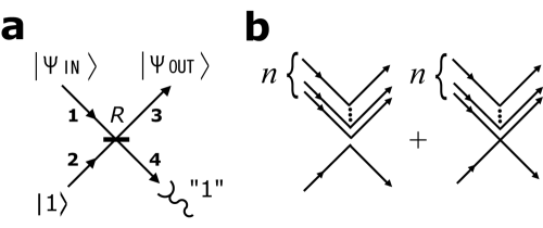
A simplified version of NS operation is shown in Fig.1(a). An input state, , impinges on a beam-splitter (BS) with reflection probability ; a single ancilla photon, impinges from the other side of the beam splitter. The two input modes, 1 and 2, undergo a unitary transformation into two output modes, 3 and 4, described by and . The NS operation is successful when one and only one photon reaches the detector in mode 4. Provided the photons are indistinguishable, the two paths leading to exactly one photon in mode 4 will interfere. Either all photons are reflected or of the photons in mode 1 are reflected and 1 photon in each of modes 1 and 2 are transmitted. When a single photon ends up in mode 4, the photon number state undergoes the following transformation:
| (1) |
where the unusual normalization of the output state reflects the probability amplitude of success. The sign of the phase shift depends on the number of incident photons and the reflection probability of the BS. For , the sign of the amplitude is unchanged and for it picks up a negative sign. For the critical case, where , the output probability amplitude becomes zero. This is due to the generalized Hong-Ou-Mandel-style interference effectHong . In our proposal, the extension of the NS operation to include a second polarization mode is straightforward. We inject a horizontally-polarized ancilla photon into the BS in Fig. 1 and consider only the cases where the single photon detected in mode 4 is horizontally polarized. The transformation for the horizontal polarization is as in (1). There is only 1 possible path which leads to no vertically-polarized photons in mode 4; that is for all vertically-polarized photons to be reflected. This operation for the input state with vertically-polarized photons and horizontally-polarized photons is given by:
| (2) |
where and are the reflection probabilities for vertical and horizontal polarization respectively. As expected, the vertical photon number, , does not appear in the square bracket nonlinear-sign term. The only change the vertically-polarized photons contribute is the reflection amplitude raised to the power of .
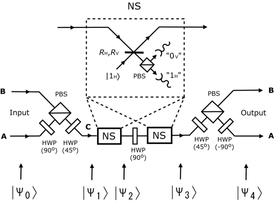
The operation of CS gate is constructed on the setup using two such polarization-based NS gates and linear-optics element shown in Fig. 2. The inset shows the detail of the polarization-based NS gate. It is constructed using a beam splitter with polarization-sensitive reflectivity probabilities and and single-photon detectors. Single-photon sources, are injected into one input port of BS’s as ancilla. The successful operation is signaled when the single photon detector monitoring the horizontal mode in each NS operation detects exactly one photon and no vertically-polarized photons are detected using a polarizing beam-splitter (PBS) and single-photon detectors.
We consider input states that are superpositions of , , and ,where all of the photons are horizontally polarized. This forms a computational space for 2 qubits. The general input state for the gate is described as:
| (3) |
The two input optical modes are combined into a single spatial mode using a HWP that rotates the polarizations by 90 degrees and a PBS. Once in the same spatial mode, second HWP rotates the polarizations by 45 degrees. Following the transformation by the setup, the combined state in mode C is described as:
| (4) | |||||
The first NS operation is applied for and affects only the horizontal component of the state. Following the polarization based NS operation (2), the state in mode C is undergoes the following transformation:
| (5) | |||||
A HWP that rotates the polarizations by 90 degrees after the first NS gate exchanges the roles of horizontal and vertical polarization. Then, the second NS operation is applied and affects the horizontal component of the state.
| (6) | |||||
Using the final HWP rotates the polarizations by 45 degrees and a polarizing beam-splitter (PBS), and HWP rotates the polarizations by -90 degrees combination, the photons are split up again into two different spatial modes and returned to the same polarization states.
| (7) | |||||
When the BS has reflection probabilities:
| (8a) | |||||
| (8b) |
then achieving and the two-qubit CS gate is implemented because all probability amplitudes of the output states for , , and become equal. The required reflectivities are the same as those of non-polarizing beam splitters for the Ralph’s gate and both of the gates give the same probability of successful operationRalph . The success probability is given by . This two-qubit gate is non-deterministic, however near deterministic operation is possible when the gate is used in conjunction with a quantum teleportation protocol Knill ; Gottesman . Universal quantum computation is then possible with this two-qubit gate together with all single-qubit rotations from a universal set Sleator ; Barenco .
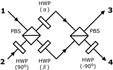
One could, in principle, build a custom optical beam splitter (i.e. dielectric filters) with the desired reflectivities to satisfy (8a) and (8b) - in this case the scheme has no phase sensitivity whatsoever. However, building such an optic might have technology (and cost) constrains; here we describe a simple method to construct such a polarization-sensitive beam splitter using standard polarization optical components with the tradeoff of accepting some phase sensitivity. This polarization sensitive variable beam splitter can be constructed constructed by two PBS’s and four HWP’s that is shown in Fig. 3. The first (last) HWP that is placed on mode 2 (4) rotate the polarization state 90 (-90) degrees. The middle two HWP’s in the interferometer rotate the polarization state arbitrary angles and . The two input modes, 1 and 2, undergo a unitary transformation into two output modes, 3 and 4. The vertically-polarized photon is described by
| (9a) | |||
| (9b) |
and the horizontally-polarized photon is described by
| (10a) | |||
| (10b) |
and are determined by the rotation angles and , and become and . When the angles are set 29.5 degrees and 61.6 degrees, required reflectivities (8a) and (8b) is satisfied.
This theoretical paper details how our recently demonstrated nonlinear sign shift gate can be used to construct the requisite two-qubit conditional phase gate for scalable linear optics quantum computationSanaka2 . The typical 50/50 BS, where , is used for the experiment. The presented scheme is the readily feasible extension of the experiment by simply using two NS gates and changing the reflectivity of the BS. The scheme herein is also designed to eliminate all or most of the phase sensitivity inherent in other linear optics gates to simplify the experimental implementation. We have also described a simple method for building polarization sensitive variable beam splitters - such an object may have other uses in quantum optics like optimal phase covariant cloning of photonic qubitsFiurasek . This work and the recent results bring linear optics quantum computation and information processing closer to a reality.
This work was supported by the Austrian Science Foundation (FWF), project numbers M666 and SFB 015 P06, NSERC, and the European Commission, contract number IST-2001-38864.
References
- (1) K. Knill, R. Laflamme, and G. J. Milburn, Nature (London) 409, 46 (2001).
- (2) K. Sanaka et al., Phys. Rev. Lett.92, 017902 (2004).
- (3) P. W. Shor, in Proceedings of the 35th Symposium on Foundation of Computer Science 124-133 (IEEE Comp. Soc. Press, Los Alamos, CA, 1994).
- (4) L. K. Grover, Phys. Rev. Lett. 79, 325 (1997).
- (5) Q. A. Turchette et al., Phys. Rev. Lett. 75, 4710 (1995).
- (6) A. Rauschenbeutel et al., Phys. Rev. Lett. 83, 5166 (1999).
- (7) K. J. Resch, J. S. Lundeen, and A. M. Steinberg, Phys. Rev. Lett. 89, 037904 (2002).
- (8) S. E. Harris and L. V. Hau, Phys. Rev. Lett. 82, 4611 (1999).
- (9) M. M. Kash et al. Phys. Rev. Lett. 82, 5229 (1999).
- (10) J. D. Franson, Phys. Rev. Lett. 78, 3852 (1997).
- (11) D. Gottesman, I. L. Chuang, Nature (London) 402, 390 (1999).
- (12) T. C. Ralph, A. G. White, W. J. Munro, and G. J. Milburn, Phys. Rev. A. 65, 012314 (2001).
- (13) E. Knill, Phys. Rev. A. 66, 052306 (2002).
- (14) M. Koashi, T. Yamamoto, N. Imoto, Phys. Rev. A. 63, 030301(R) (2001).
- (15) T. B. Pittman, B. C. Jacobs, and J. D. Franson, Phys. Rev. A. 64, 062311 (2001).
- (16) X. B. Zou, K. Pahlke, and W. Mathis, Phys. Rev. A. 65, 064305 (2002).
- (17) H. F. Hofmann and S. Takeuchi, Phys. Rev. A. 66, 024308 (2002).
- (18) K. Sanaka, K. Kawahara, and T. Kuga, Phys. Rev. A. 66, 040301(R) (2002).
- (19) A. P. Lund, T. B. Bell and T. C. Ralph, Phys. Rev. A. 68, 022313 (2003).
- (20) C. K. Hong, Z. Y. Ou, and L. Mandel, Phys. Rev. Lett. 59, 2044 (1987).
- (21) T. Sleator and H. Weinfurter, Phys. Rev. Lett. 74, 4087 (1995).
- (22) A. Barenco et al., Phys. Rev. A. 52, 3457 (1995).
- (23) J. Fiurasek, Phys. Rev. A. 67, 052314 (2003).