Photon number resolving detection using time-multiplexing
Abstract
Detectors that can resolve photon number are needed in many quantum information technologies. In order to be useful in quantum information processing, such detectors should be simple, easy to use, and be scalable to resolve any number of photons, as the application may require great portability such as in quantum cryptography. Here we describe the construction of a time-multiplexed detector, which uses a pair of standard avalanche photodiodes operated in Geiger mode. The detection technique is analysed theoretically and tested experimentally using a pulsed source of weak coherent light.
I Introduction
Detectors that can resolve the number of photons in a pulse of light have a number of applications in the preparation and detection on non-classical states of radiation. For example, a linear optics approach to quantum computation KLM ; LOFranson requires reliable creation of states with superpositions of up to two photons. One method of creating nonclassical states is via conditional state preparation Konrad ; Pittman ; Loock , which relies on the ability to distinguish states of different photon number. Photon number-resolving detectors could also enhance the security of quantum cryptography against certain eavesdropper attacks Hwang ; Christine .
According to the quantum theory of photodetection, the signal obtained from an ideal noise-free detector has a discrete form corresponding to the absorption of an integer number of quanta from the incident radiation. In most practical systems, however, the granularity of the output signal is concealed by the imperfections of the detection mechanism. For example, when very low light levels are detected using avalanche photodiodes (APDs) operated in the Geiger-mode, the electronic signal can be reliably converted into a binary message indicating with high fidelity whether an absorption event has occurred or not. However, the gain mechanism necessary to bring the initial energy of absorbed radiation to the macroscopic level saturates already with the absorption of a single quantum, thus completely masking the information on exactly how many photons have triggered that event. A similar problem affects most photomultipliers and APDs operated in the gain mode woodward , where the excess noise of the gain mechanism makes discrimination of multi-photon detection events practically impossible. Photomultiplier tubes have been used in the past, however, have been used to attain information about the photon statics of light pulses Kumar.
Many approaches have been taken to construct detectors with photon number resolution. These include several cryogenic devices being developed for the purpose of resolving photon numbers, including the VLPC yamamoto , a superconducting bolometer NIST , and a superconducting transimpedance amplifier sobolewski . There have also been proposals to use coherent absorption of light in an atomic vapor to enable high efficiency photon number resolving detection Kwiat ; Imm , though no such device has been experimentally demonstrated to date. However, the quantum efficiencies of these available detectors are well below the efficiency of conventional avalanche photodiodes (APDs), excepting the VLPC, which has a very high intrinsic quantum efficiency.
Unfortunately APDs do not have the ability to distinguish between different photon number states. They do however have quantum efficiencies as high as , they are commercially available, and are easy to operate. It is these attributes that make APDs desirable and prompted the proposal for their use in a fibre-based detection scheme that allows photon number resolving detection BanaszekWalmsley . In this proposal it was shown that, in principle, it is possible to retain the quantum efficiencies of the APD while adding the ability to resolve photon number. Losses critically affect this ability, since they remove photons randomly from the input state. Clearly losses in the optical system will also affect the fidelity of conditional state preparation. However, exploiting prior information, e.g. known correlations between the signal and idler modes of downconversion PDC , it is possible to significantly improve our confidence of the measurements by inductive inference using Bayes’ theorem.
In this paper, we provide a detailed analysis of two recent experiments US ; THEM which follow the main concept developed in BanaszekWalmsley , but avoids the need for optical switches czech ; czech2 . The basic idea is very similar to the detector cascade concept cascade , which uses beam splitters to split a pulse into spatial modes, each of which is monitored with an APD. Here, instead of splitting the incident pulse into spatial modes we split it into temporal modes, separated by a time interval of , divided equally between two spatial modes. Using temporal modes rather than spatial modes gives the distinct advantage that only two APDs are needed no matter how many times the pulse is split. This is a significant improvement over the APDs that are necessary in early detector array schemes cascade ; cascade2 ; cascade3 ; cascade4 though there is a trade-off between the number of modes and the detection rate of the detector.
II Experimental setup
II.1 Detector construction
The general scheme for the fibre-assisted time-multiplexed detector (TMD) is shown in Fig. 1. It consists of various lengths of single-mode optical fibre and symmetric fibre couplers. Light pulses propagating in a single-mode fibre are incident upon one input of a coupler whilst the other input has no incident light. The pulse is split into two modes at the coupler where one mode is a fibre of negligible length and the other has a much longer length . This coupler can be described by the operator transformation
| (1) |
where the operators and are the creation operators for photons in the short and long fibre, respectively. This first pair of short and long fibres along with the coupler that recombines them will be referred to as the first stage of the TMD. After the recombination at this coupler there will be four modes: two temporal modes in each of the two spatial modes. The length of the fibre creates a delay between the pulses, , where is the group index of the fibre and is the speed of light in vacuum. This time delay is chosen to be substantially longer than the deadtimes of the APDs. The two commercial silicon APD single photon detectors (Perkin Elmer SPCM-AQR-13) used had estimated deadtimes of 50–60 ns. Therefore the length was chosen to be approximately 25 meters, making ns. The length and the deadtimes of the APDs determines the maximum duration of the pulses that can be measured by the TMD. If a pulse were longer than the , the APDs would not always have time to recover from the detection event from one mode before the light from the subsequent temporal mode arrived at the APD.
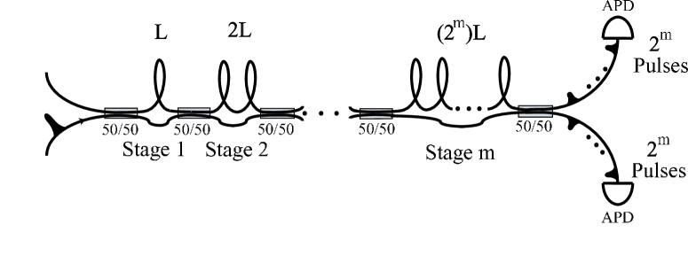
Generally, any number of stages may be concatenated together, where each successive stage has a fibre of length , where refers to the stage number. The second fibre that connects the couplers is too short to be of consequence and all the couplers can be described by transformations similar to Eqn. 1. If stages are used, then the pulse will be distributed amongst modes, in each output fibre from the final 50/50 coupler. The time it takes for the light to traverse the longest path of the TMD must be larger than the time between incident pulses in order to prevent signals from two different pulses being in the fibre at the same time. Although increasing the number of stages allows one to detect higher photon numbers, the time separation between temporal modes limits the effective response time of the TMD. Therefore the maximum repetition rate possible is approximately for the two stage TMD and about MHz for the three stage detector.
Two TMDs were constructed and tested; a two stage device US and a three stage device THEM . The two stage TMD was fabricated with single mode optical fibers at 780 nm (Lucent SMC-AO780B). A standard laser diode pulsed at 777nm was used as the light source in the two stage TMD experiments. The pulse duration was approximately 14 ns and the repetition rate was 10 kHz. The three stage TMD was also built from single mode fiber supporting visible light propagation (610 nm to 730 nm) (3M FS-SN-3224). The light source in these experiments was a laser diode at 680 nm with 50 ps pulse duration and 20 kHz repetition rate. The choice of wavelength was based on a balance between detector efficiencies and fibre losses. The losses in fibres at telecom wavelengths are lower than in the near infrared, but APDs are less efficient at such wavelengths and have higher dark count rates.
II.2 Collecting data
Data collection for the two stage TMD was performed using a digital oscilloscope. The oscilloscope was controlled by a PC and used the same trigger as the laser diode that created the light pulses. The intensity of the laser diode was attenuated with neutral density filters and the photon distributions were reconstructed from laser pulses. The key information extracted from single-shot measurements was the number of pulses counted by the two APDs and their times of arrival (TOA) after the trigger pulse. Plotting the counts against the TOA, we can clearly identify eight temporal modes (see Fig. 2), which are well separated from one another. This data allows us to perform two tasks. First, by integrating the counts in each mode we can determine the probability that a single photon will end up in that mode. Ideally the probability for a photon to end up in each mode would be equal, but due to losses in the different lengths of fibre and imperfect couplers, the probabilities differ slightly from .
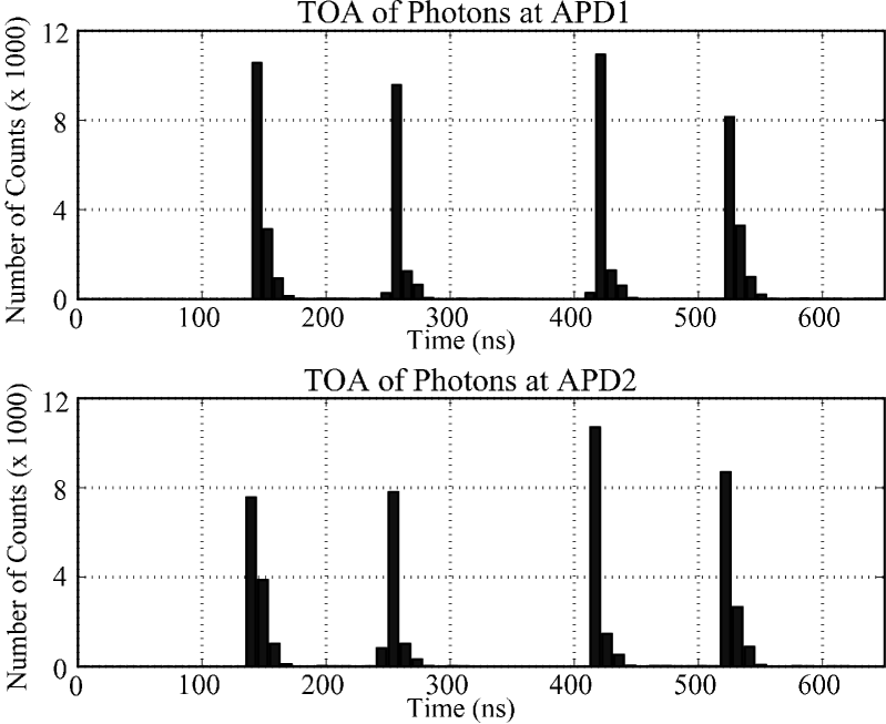
Secondly, using the TOA plot we can apply gating to the signal from the APDs. This will reduce false counts from dark counts and afterpulsing. These false counts could be neglected in our experiment (they are not visible at the scale of Fig. 2) except for coherent pulses that have a non-zero probability of detecting photon numbers equal to the number of modes, . In this case gating can play an important role (see discussion below).
Afterpulsing is caused by the release of a charge that was caught in the depletion layer of the APD in the course of the previous avalanche. Detection events arising from afterpulsing usually occur as soon as the bias voltage across the diode returns to the breakdown voltage, which means that the time between an event triggered by a photon and the afterpulse will be on the order of the deadtime of the detector. Therefore we expect afterpulsing events in a time window of about 50–60 ns after each temporal mode. Determining the afterpulse frequency involved counting the coincidences in a single shot measurement of an event within the specified temporal mode of the TMD with an event occurring 50–60 ns after the time window of the temporal mode. The event detected outside the allowed time window of the temporal mode was then labelled as an afterpulsing event. It was found that approximately of the events outside the gate window were due to afterpulsing. Accepting pulses only within a specified time window allowed us to reduce the effects of both afterpulsing and dark counts.
The three stage detector counted photon statistics using a custom-made electronic circuit that only allowed detection in a specified time window after each trigger THEM .
III Theory and data analysis
III.1 Conditional probabilities
In general, the count statistics that are recorded by the APDs do not represent the photon statistics of the incident pulses. For the moment, we will assume that losses can be represented by a beam splitter before the TMD (see section III.3 for further discussion). With this assumption, the counting statistics are related to the incoming photon number distribution by
| (2) |
where is the probability of detecting counts, is the probability that there was photons incident on the TMD, and is the conditional probability that counts are detected when photons are incident on the TMD. Eqn. 2 can be represented as a matrix equation and from this point forward, all equations will be written in matrix form. For this purpose, we associate elements of the conditional probability matrix with the conditional probabilities by the equation , and the elements of and are and, respectively. In matrix notation, Eqn. 2 becomes
| (3) |
The conditional probabilities can be calculated from a simple stochastic model. The problem reduces to the archetypal probability theory example of taking balls, randomly distributing them amongst bins and calculating the probability that bins are occupied. Since this is a photon counting experiment, the photons may be treated as balls. In this case, is the number of temporal modes, are the number of incident photons, and corresponds to the number of counts recorded in the APDs. A few results are given below in order to illustrate how the conditional probabilities were calculated:
-
•
Case 1: or – Assuming we can ignore dark counts and afterpulsing, it is obvious that we will never detect more counts in the APDs than the number of incident photons. Therefore for and for .
-
•
Case 2: – If we distribute a single photon amongst modes, one and only one mode must be occupied since the losses are being ignored; therefore .
-
•
Case 3: – Distributing two photons into modes can only result in either one or two modes being occupied. The probability that two modes are occupied, i.e. we detect two counts, is then, and the probability that only one mode is filled, i.e. that both balls are in the same mode, is , where is the probability that a photon will end up in mode .
-
•
Case 4: – This a specific example of one of the more complex conditional probabilities. In this case the APDs count four photons when seven photons were incident on the TMD. The equation that describes this probability is:
(4) The binomial coefficients account for the different ways the photons can be distributed amongst the modes and the factorial in the denominator corrects for the overcounting due to having three modes occupied by the same number of photons.
Note that this approach is general enough to apply to a TMD with any number of temporal modes and allow each temporal mode to have its own unique probability of containing a photon. These different probabilities were obtained from the integration of the temporal modes in Fig. 2 and resulted in the probabilities: (0.141, 0.112, 0.125 0.121, 0.132, 0.105, 0.134, 0.129), which are all close to . The conditional probabilities were worked out for several different mode weights and it was shown that small deviations from do not dramatically affect the . Still, the different weights were kept in the analysis to obtain the best accuracy.
The conditional probability matrix is a matrix. We include the terms, as they become important when we discuss losses (see Sect. III.3). For the eight weights of the temporal modes given above, the result is:
| (5) |
The procedure for obtaining the photon number distribution from the count statistics using this matrix and Eqn. 3 is described in the next section.
III.2 Photon number reconstruction
In our experiments, we take data over a large number of laser pulses and reconstruct the photon number distribution from the count statistics of the APDs. Because we use a coherent light source, the photon number distribution is Poissonian :
| (6) |
where is the mean photon number and is the number of photons. In general losses modify the photon distribution of a quantum state. Such is the case with Fock states and squeezed states. However, for a coherent state losses simply reduce the mean of the distribution, leaving the higher moments of the probability distribution as they were. We therefore introduce , where takes into account both the lossy fibers and the inefficiency of the detectors. Several approaches can be taken to determine from and each method implies a different set of assumptions. Our first two methods assume that the distribution will be Poissonian, but the third is more general, as it assumes nothing about the form of the distribution.
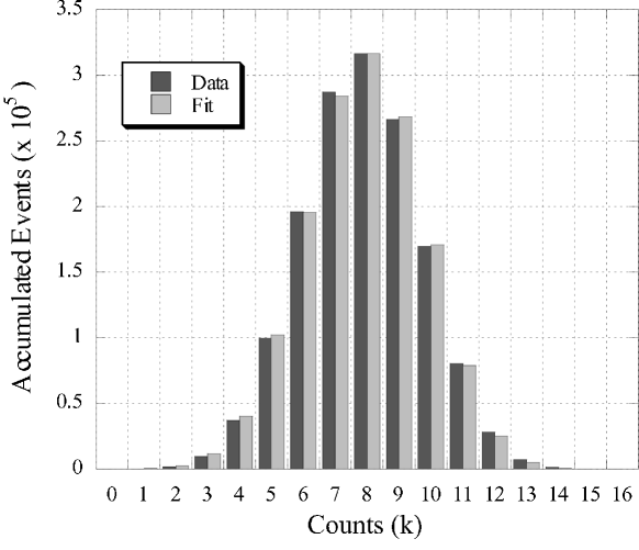
The first method assumes that each temporal mode of the TMD is equally likely to contain a photon. This implies the different length fibres do not affect the losses in anyway and that the couplers are perfect. By using instead of in Eqn. 6, we see that the probability of detecting no photons is and the probability of detecting at least one photon is . Since the input state is assumed to be coherent, there exist no correlations between the measured counts and the detection of photons in each of the temporal modes is independent. Hence the probability of obtaining exactly detection events is given by the binomial distribution
| (7) |
where is again the number of temporal modes in the TMD.
Fitting experimental data from the three stage TMD to Eqn. 7 with the mean photon number and a normalisation constant as fit parameters, reveals how well this simple theoretical model works. Experimental data for is shown in Fig. 3. The deviations of the experiment from the theory are likely to be from assuming equal weighting of each temporal mode.
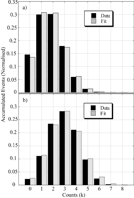
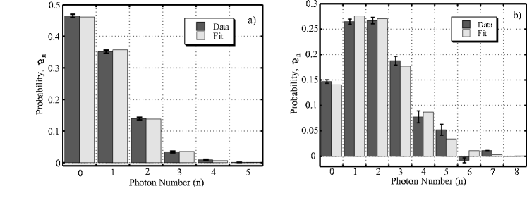
The second method of determining the incoming photon distribution employs the conditional probability matrix in conjunction with Eqn. 3 and uses a least-squares routine to fit the data to a Poissonian distribution. This is accomplished by assuming a Poissonian distribution of different mean value for , acting on it with , and comparing the resulting with the data. The mean photon number of the light pulses are obtained from the modified Poissonian distribution that varied least with the experimental data. Experimental count statistics from the two stage TMD are shown with their associated fits for and in Fig. 4a and 4b, respectively.
The third method of reconstructing the photon statistics makes no assumptions, not even about the form of the photon statistics. It is the most general way to determine the input number distribution, but is less robust than the previous two methods. Inverting Eqn. 3, we obtain:
| (8) |
This inversion breaks down if there are many events with . Inspection of the conditional probability matrix reveals the reason for this failure: is an upper triangular matrix with the lower-right diagonal elements having very small values. Thus the matrix is singular and cannot be inverted. If the data contains events where for a value of corresponding to one of these large elements, the reconstructed photon number distribution will acquire unphysical properties such as negative probabilities and probabilities greater than one. It is important to re-emphasize that these unphysical results are a result of the instability of the inversion. Experimental data was inverted to give the photon probability distributions for three different coherent states: one possesses an easily invertible photon number (), the second has a mean that is on the border of being invertible and being singular (), and the last is a state well above the point of inversion failure ()(see Fig. 5a, 5b, and 6 respectively). The error bars in Fig. 5 were determined from 1000 Monte Carlo simulations of the experiment with the appropriate number of pulses (). Error bars are not shown in Fig. 6 because the inversion is too unstable for error bars to be meaningful.
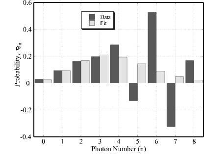
It should be noted that this inversion process can be improved, as we put no constraints on the inversion. It is certainly possible to force the inversion algorithm to exclude unphysical results such as negative probabilities or probabilities greater than one. If these constraints were implemented and a maximum likelihood technique Max-Like was used, then the inversion would most likely work both more accurately and for higher photon numbers.
III.3 Losses
In the previous analysis losses were ignored because they did not affect the distributions of the coherent states that were used in the experiment. However, as previously stated, for nonclassical states the efficiency of the detector is crucial. The largest sources of loss arise from coupling into the fibre, absorption and scattering of light inside the fibre, and the imperfect efficiencies of the APDs. The absorptive losses depend on the amount of fibre through which the light travels. For a fibre of length , the fraction of the incident power that is transmitted will be . The transmission through a fibre of length is then , etc.
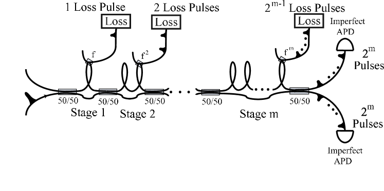
One way to simulate the effect of the lossy fibre (used for the three stage TMD) is to model it as a section of lossless fibre () followed by a coupler in each stage of the TMD (see Fig. 7). These additional couplers transmit a fraction of the light and reflect of the light into a different fibre. It is assumed that the short sections of fibre connecting the couplers have negligible losses. This creates extra loss modes, each with a different probability of being occupied by a photon. These extra modes can be treated in the same manner as the regular temporal modes of the TMD except that the photons of the lossy modes will not be detected. After all the transformations (see Eqn. 1) for both the actual couplers and the loss couplers are applied, the input state can be written as a large number of terms that correspond to all the ways that the incident photons can be distributed over all 23 modes, for the three-stage TMD.
In order to account for the nonunit efficiency of the APDs, we will assume that , where is the probability that the APD detects no photons when photons are incident upon it. The probability of detecting at least one photon is then . The value of , and hence , were determined experimentally and the probability of obtaining detection events was calculated. This contribution was then added to the probability distribution for each term of the state.
This method of modelling the losses focussed on the experimental setup and the actual sources of the loss. We can, however, think about the losses, and the experiment in general, in a more abstract manner. By doing so we allow for a much more general method of taking losses into account. The first aspect changed to make the scheme more abstract will be to simply think of the TMD as a device that splits a pulse into modes (see Fig. 8). The other input modes of this multi-port beam splitter have been ignored as they are left in the vacuum state and therefore play no role in the model. We don’t care how the modes were created nor do we care what type of modes they are (i. e. temporal or spatial). These modes only have a few qualities that are of importance:
-
1.
Each mode is easily distinguishable from the others due to the orthogonality of the modes.
-
2.
There are no losses other than the initial beam splitter.
-
3.
In general, each mode will have a different probability of containing a photon.
Loss is introduced into the system by placing a single beam splitter before the multi-port beam splitter. This beam splitter reflects a fraction, of the incident light. Since this is the only source of loss in the scheme, . It can be shown that by choosing appropriate values of and , the losses from the method shown in Fig. 7 can be recreated.

Another important attribute of the abstract loss model is that the loss becomes independent of the conditional probability matrix. This makes the analysis of how losses affect the TMD’s performance much simpler since Eqn. 3, with losses, becomes:
| (9) |
where is another upper triangular conditional probability matrix with elements given by the binomial distribution
| (10) |
where is the photon number after losses are taken into account. Note that Eqn. 9 is only valid for and for .
The conditional probability matrix no longer acts on the photon number distribution directly, but on the reduced distribution. With this method, retrieving the photon number distribution is done in precisely the same way as before (Eqn. 8), except the matrix we invert is the combination of the two matrices, and :
| (11) |
Similar methods for compensating losses in photodetection have previously been discussed Loss ; Konrad_Loss .
IV Applications
With the use of Eqn. 11 we can completely reconstruct the photon probability distribution of an optical pulse given a large number of single shot measurements of identical pulses. Reconstructing coherent state photon statistics is a good proof of principle experiment, but is not the primary application of the TMD.
IV.1 Reconstructing Fock States
Thus far we have only considered coherent states of light, where losses were less important; it is crucial to minimise losses for Fock states. Schemes for linear optics quantum computing are concerned with distinguishing the presence of one or two photons KLM ; LOFranson ; LOQC1 ; LOQC2 ; LOQC3 and conditional state preparation depends on being able to measure three photon states. To illustrate the effects losses have on a Fock state measurement, Fig. 9 shows for a detector with efficiency and all other losses set to zero. Fig. 9a (b) is the result for the three (two) stage TMD. Notice that more stages could further improve the capabilities of the apparatus, but eventually the losses and lowered detection rate from adding more stages would render the detector less useful.
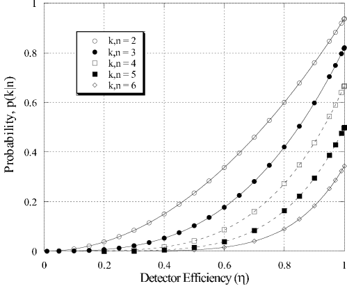
The effects of losses are further demonstrated in Fig. 10 by looking at how the of the three stage TMD varies for different detector efficiencies. All other losses being negligible and assuming perfect couplers, the analytic formula for the diagonal elements of the conditional probability matrix is
| (12) |
This formula also shows the effect of having a finite number of modes in the TMD. As the number of incident photons increases, the probability of detecting all of them decreases, even for detector efficiency. This is due to the increased probability that two of the photons will be in the same mode.

IV.2 Single shot measurement
Most of our discussion thus far has revolved around the conditional probability of detecting photons if photons were actually incident on the TMD. It is interesting to look at the inverse conditional probability, that there are photons in a pulse if counts were measured. The tilde indicates that this is a different function of and than the forward probability . contains information about how certain one can be about the input photon number from a single shot measurement using the TMD. Such measurements are the main application of the TMD and needs to be well understood if one would like to perform conditional state preparation.
Using Bayes’ theorem, , the probability can be written as
| (13) |
Unlike , which only depends on the construction of the TMD, this probability is a function of the input photon distribution as well. The in Eqn. 13 is the matrix element that results from combining the conditional probability matrix and the loss matrix. This matrix transforms the incoming photon number into the count distribution. Substituting (the element in the th row and th column of ) and using Eqn. 9 to rewrite , Eqn. 13 becomes
| (14) |
where everything is now in terms of the input distribution and the conditional probability matrices.
The conditional probability is a useful way to evaluate the performance of the TMD. It depends critically, however, on the a priori input photon distribution used in the analysis. For example, the Fock state with photon number has a photon number distribution vector that is , meaning that the probability of there being a photon incident on the detector is zero unless , in which case the probability is one. If we put this into Eqn. 14 for , the result is zeros for all except for , where the value is unity. This indicates that no matter what number of photons are detected, we are confident that we measured the Fock state . This seems like a fruitless analysis at first, but the reason for the trivial result is that one must assume the photon probability distribution is already known. In this case, we assumed the state was in a specific Fock state. Therefore no matter what the result of the photon number measurement, the answer will always tell us that we are confident we measured .
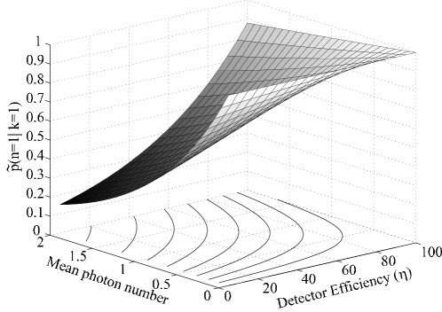
The problem arises from the fact that the TMD is performing a projective measurement in the photon number basis and the Fock state is an eigenstate of this projection operator. If we use states that are not eigenstates of the measurement, such as a coherent state or a mixture of Fock states which we wish to distinguish, the result is nontrivial and information is gained from the measurement. Fig. 11 shows a plot of versus detector efficiency and mean photon number of the coherent state and essentially characterises the performance of a single-shot measurement of a coherent state using a two stage TMD. It is clear that either a decrease in detector efficiency or an increase in mean photon number will degrade the TMD performance. For good performance low photon numbers should be used. Notice that does not necessarily approach zero, which seems counterintuitive at first, especially for a detector efficiency that approaches zero. One must remember, however, that this conditional probability is not the probability of detecting a photon (which does go to zero as the efficiency decreases) but is the probability that if a photon was detected, no matter how unlikely it may be, that there was exactly one photon in the pulse 111In a realistic experiment, detector dark counts will be present, but can be suppressed with narrow time-gating. We assume in the present analysis that dark counts are completely negligible.
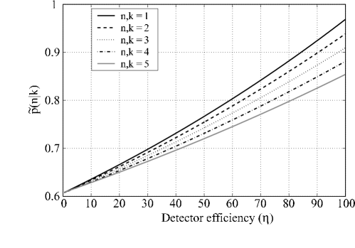
A plot similar to Fig. 11 can be constructed for higher photon numbers, . These plots all look very similar but with lower probabilities in general. To illustrate this Fig. 12 shows a plot of versus the detector efficiency for a coherent state of mean photon number equal to for different values of . For , this plot is a cross-section of the plot in Fig. 11.
V Summary
In summary, we have described in detail the construction and performance of a time-multiplexed single-photon detector with photon number resolution. The TMD is easily constructed from single-mode optical fibre, 50/50 couplers and two standard silicon APDs and does not require extreme operating conditions like other photon resolving detectors. Both two US and three THEM stage detectors were constructed, creating eight and sixteen modes respectively, and the TMD is extendible to any number of stages, limited by the losses introduced by each additional stage.
The photon statistics of different coherent states of light were experimentally reconstructed as a proof-of-principle experiment. Good agreement was seen between the experiment and the theories developed to model the action of the TMD.
An analysis of the single-shot performance of the detector shows that the TMD can be a useful tool for conditional state preparation and other quantum information schemes since the conditional probability of a single count being caused by single photon remains reasonably high even for inefficient detectors.
Acknowledgements
We are grateful for conversations with C. Radzewicz and M. T. Lamar. This research was supported by the US Department of Defense through the Army Research Office via grant number DAAD19-02-1-0163 (Oxford) and ARO, NSA, ARDA, and IR&D (Applied Physics Laboratory). C. Śliwa’s current address is: Centre for Theoretical Physics, Al. Lotnikow 32/46, 02-668 Warszawa, Poland.
References
- (1) Knill, E., Laflamme, R., and Milburn, G. J., 2001, Nature, 409, 46.
- (2) Franson, J. D., Donegan, M. M., Fitch, M. J., Jacobs, B. C., and Pittman, T. B., 2002, Phys. Rev. Lett., 89, 137901.
- (3) Śliwa, C., and Banaszek, K., 2003, Phys. Rev. A, 67, 030101(R) .
- (4) Pittman, T. B., Donegan, M. M., Fitch, M. J., Jacobs, B. C., Franson, J. D., Kok, P., Lee, H., and Dowling, J.P., 2003 quant-ph/0303113.
- (5) van Loock, P., and Lütkenhaus, N., 2003, quant-ph/0304057.
- (6) Hwang, W. Y., 2003, quant-ph/0211153.
- (7) Calsamiglia, J., Barnett, S. M., and Lüetkenhaus, N., 2002, Phys. Rev. A, 65, 012312.
- (8) Woodward, N. G., Hufstedler, E. G., and Lafyatis, G. P., 1994, Appl. Phys. Lett., 64, 1177.
- (9) Bondurant, R. S., Kumar, P., Shapiro, J. H., and Salour, M. M., 1982, Optics Lett., 7, 529.
- (10) Kim, J., Takeuchi, S., Yamamoto, Y., and Hogue, H. H., 1999, Appl. Phys. Lett., 74, 902.
- (11) Cabrera, B., Clarke, R. M., Colling, P., Miller, A. J., Nam, S., and Romani, R. W., 1998, Appl. Phys. Lett., 73, 735.
- (12) Somani, S., Kasapi, S., Wilsher, K., Lo, W., Sobolewski, R. and Gol’tsman, G. N., 2001, J. Vac. Sci. Technol. B, 19, 2766.
- (13) James, D. V. F., and Kwiat, P. G., 2002, Phys. Rev. Lett., 89, 183601.
- (14) Imamoḡlu, A., 2002, Phys. Rev. Lett., 89, 163602.
- (15) Banaszek, K., and Walmsley, I. A., 2003, Optics Lett., 28, 52.
- (16) Mandel, L., and Wolf, E., 1995 Optical Coherence and Quantum Optics (Cambridge: Cambridge University Press).
- (17) Achilles, D., Silberhorn, Ch., Śliwa, C., Banaszek, K., and Walmsley, I. A., 2003, Optics Lett., accepted; see also quant-ph/0305191.
- (18) Fitch, M. J., Jacobs, B. C., Pittman, T. B., and Franson, J. D., 2003, Phys. Rev. A, accepted; see also quant-ph/0305193.
- (19) Řeháček, J., Hradil, Z., Haderka, O., Peřina, J., and Hamar, M., 2003, quant-ph/0303032.
- (20) Haderka, O., Hamar, M., and Perina Jr., J., 2003, quant-ph/0302154.
- (21) Kok, P., and Braunstein, S. L., 2001, Phys. Rev. A, 63, 033812.
- (22) Song, S., Caves, C. M., and Yurke, B., 1990, Phys. Rev. A, 41, 5261.
- (23) Paul, H., Törmä, P., Kiss, T., and Jex, I., 1996, Phys. Rev. Lett., 76, 2464.
- (24) Kok, P., 2003, quant-ph/0303102.
- (25) Banaszek, K., 1998, Phys. Rev. A, 57, 5013.
- (26) Kiss, T., Herzog, U., and Leonhardt, U., 1995, Phys. Rev. A, 52, 2433.
- (27) Banaszek, K., 1999, J. Mod. Optics, 46, 675.
- (28) Pittman, T. B., Jacobs, B. C., and Franson, J. D., 2001, Phys. Rev. A, 64, 062311.
- (29) Pittman, T. B., Jacobs, B. C., and Franson, J. D., 2002, Phys. Rev. Lett., 88, 257902.
- (30) Pittman, T. B., Fitch, M. J., Jacobs, B. C., and Franson, J. D., 2003, quant-ph/0303095.