Absorption resonance and large negative delay in Rb vapor with buffer gas.
Abstract
We observe a narrow, isolated, two-photon absorption resonance in 87Rb for large one-photon detuning in the presence of a buffer gas. In the absence of buffer gas, a standard configuration of two laser frequencies gives rise to electromagnetically induced transparency (EIT) for all values of one-photon detuning throughout the inhomogeneously (Doppler) broadened line. However, when a buffer gas is added and the one-photon detuning is comparable to or greater than the Doppler width, an absorption resonance appears instead of the usual EIT resonance. We also observe large negative group delay ( for a Gaussian pulse propagating through the media with respect to a reference pulse not affected by the media), corresponding to a superluminal group velocity .
pacs:
270.1670, 270.5530Quantum coherence effects have attracted great attention the last few years. Phenomena such as ultra-low optical group velocity Hau et al. (1999); Kash et al. (1999); Budker et al. (1999); Godone et al. (2002), super-luminal group velocity Godone et al. (2002); Wang et al. (2000); Akulshin et al. (2003), enhanced nonlinear optical effects Harris and Hau (1999), and quantum information storage Phillips et al. (2001); Liu et al. (2001); Zibrov et al. (2002) have all been studied under the condition of electromagnetically induced transparency (EIT) Harris (1997). More recently, complementary coherence effects such as electromagnetically induced absorption (EIA) have been predicted and studied Akulshin et al. (2003, 1998); Taichenachev et al. (2000); Ye et al. (2002). In the Letter, we present the experimental observation of a new narrow absorption resonance appearing at large optical density and large detuning in Doppler broadened media with buffer gas.
In typical experiments, the narrow transmission linewidth in EIT is limited by the relaxation rate of the ground-state coherence, which is usually determined by the interaction time of an atom with the applied laser radiation. Two common methods for increasing the interaction time are by use of wall coatings Budker et al. (1998) that allow an atom to maintain its coherence while it travels into and out of the interaction region many times, and by use of a buffer gas that allows the atom to diffuse out of the interaction region slowly by velocity changing collisions that still preserve the ground-state coherence Brandt et al. (1997); Erhard and Helm (2001).
For a -type EIT system, the dependence of the EIT resonance on one-photon laser detuning has been studied experimentally Knappe et al. (2003) and theoretically Taichenachev et al. (2002). They show that in the limit of high buffer gas pressure, when the decay rate of the upper level is comparable with the Doppler broadening, the EIT resonance shape can be described by a Lorentzian plus a dispersion-like curve:
| (1) |
where is the width of the resonance, is the two photon detuning, is one-photon dependent resonance shift with respect to resonance position for zero one-photon detuning, is the amplitude of the Lorentzian part, is the amplitude of the dispersion-like part, and is an offset. However previous experimental studies Knappe et al. (2003) have only seen the resonance shape become somewhat assymetric while still maintaining an EIT resonance-like shape, in other words and .
In our experiment we achieve an absorption-like resonance () by detuning the drive laser into the wings of the Doppler distribution in a cell with buffer gas. For our conditions, no absorption is found without buffer gas. The absorption resonance is accompanied by large anomalous dispersion so that negative group delay is observed for a pulse propagating through the medium. It is important to stress that the previous observation of EIA in Refs. Akulshin et al. (2003, 1998); Taichenachev et al. (2000); Ye et al. (2002) and the enhanced absorption seen in the Hanle effect Dancheva et al. (2000) have a different nature than what we observe here, since those previous observations require that the degeneracy of the ground state be lower than that of the excited state Taichenachev et al. (2000), (i.e. ) for a drive field transition, which is not necessary in our experiments.
We use a weak probe and a strong drive (or coupling) field in a configuration of the two ground-state levels an the excited state of 87Rb as shown in Fig. 1. We operate in the power-broadened regime where where is the drive laser Rabi frequency, is the radiative decay rate as defined above, and is the decay rate of ground-state coherence. The resulting ground-state coherence gives rise to a narrow EIT resonance of the probe field in the vicinity of two-photon resonance (). This coherence still exists even for one-photon detunings () comparable to or somewhat greater than the inhomogeneous Doppler width of the medium.

Because of the way our probe field is generated (discussed below) a second configuration consisting of a weak Stokes component and the drive field (see Fig. 1) also is present. However, this system is detuned far from resonance, and does not affect our system notably. (Nonetheless, the propagation properties of the Stokes component are rather interesting and will be discussed elsewhere.)
Our experimental setup is shown schematically in Fig. 2. We use an external cavity diode laser tuned to the vicinity of the () transition of 87Rb . The laser is referred to as the driving field () in Fig. 1. Detuning of the drive laser() changes from zero up to 2 GHz and is always positive (for any detuning from upper levels is larger then for zero detuning as it shown in Fig. 1). Sidebands are generated on the drive laser by an electro-optic modulator (EOM) which is tunable in the vicinity of the 6.835 GHz ground state splitting. The drive laser is tuned to the transition so that the upper sideband serves as the probe field, and is tunable in the vicinity of the transition. The lower sideband (Stokes component) is far off resonance. After the EOM, all fields pass through a single-mode optical fiber to obtain a clean Gaussian spatial mode. The laser is collimated to a diameter of 7 mm, and circularly polarized with a wave-plate right before the cell. The cell itself is surrounded by 3 layer magnetic shield which suppresses the laboratory magnetic field. The cell is heated to to control the density of 87Rb vapor.
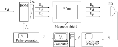
Before the EOM, part of the drive laser is split from the main beam, shifted in frequency by a small amount (60 MHz) with an acousto-optic modulator and deflected around the cell. This shifted beam is recombined with the light transmitted through the cell and all the fields are detected on a fast photodiode. This (heterodyne) procedure allows us to separately detect the transmitted probe and Stokes fields. Kash et al. (1999).
We measure the EIT spectrum (transmission as a function of two-photon detuning for various one photon detunings of the driving field (). We also measure the group delay of a pulse propagating through the cell. This is done with a programmable pulse synthesizer, which modulates the microwave generator for the EOM. We thus produce a Gaussian (temporal) pulse in the power of the drive field sidebands (the probe field). The delay time is extracted by data taking and analyzing software on a computer which collects the separate probe and reference signals.

We first measure various transmission spectra for a 87Rb cell with no buffer gas. Our measurements, shown in Fig. 3a show that the EIT resonance maintains its transmission-like shape as the drive and probe are detuned from one-photon resonance. When the lasers are far from resonance (bottom trace in Fig. 3a), the lasers interact with a very small number of atoms, and the width of the EIT resonance is determined by power broadening by the drive laser ( where is the drive Rabi frequency and is the Doppler width). When the lasers are on resonance, the effective optical density is much higher, and the EIT width is much lower than the power-broadened width Lukin et al. (1997); Sautenkov et al. (1999); Javan et al. (2002).
Next we replace the vacuum cell by a cell with 30 Torr of Ne buffer gas. Results are shown in Fig. 3b. We find that the resonance spectra for large one-photon detuning () are changed dramatically from the vacuum case just described. We see that as the one-photon detuning is increased, the EIT resonance passes through a dispersion-like shape and into an absorption-like shape.
Second, we find that this absorption-like resonance is accompanied by steep anomalous dispersion which results in a large negative propagation delay of the probe pulse with respect to a reference pulse that is not delayed by the medium. Sample pulses are shown in Fig. 4. These data show a delay produced by a long cell, implying a superluminal group velocity .

In order to gain physical insight into this new phenomenon we have made numerical simulations based on the density matrix equations coupled with a Maxwell equation description of propagation effects in steady state for low intensity of the probe field. For numerical simulation we use a 3-level atomic model coupled with probe and drive fields ( scheme).
The density matrix equations are the following:
| (2) | |||||
| (3) | |||||
| (4) | |||||
| (5) | |||||
| (6) |
where and are the Rabi frequencies of the drive and probe fields. The generalized decay rates are defined as:
| (7) | |||||
| (8) | |||||
| (9) |
Here is the polarization decay rate, is the radiative decay rate of the excited state, is dephasing rate, and is the inverse lifetime of the coherence between ground states and . Here we recall that the presence of the buffer gas affects values of both and . On one hand, as mentioned above, it allows preservation of the ground-state coherence longer, but on the other hand it broadens the optical transition, since grows linearly with buffer gas pressure Vanier and Audoin (1989).
Solving these equations in the steady state regime and assuming , we obtain the following expression for the linear susceptibility of the probe field:
| (10) |
where , is the 87Rb density, is the wavelength of the probe field, and , , are the solution of above equations in case when . Then to take into account propagation and Doppler averaging, the Maxwell equation is given by
| (11) |
has been solved numerically, where is the wavenumber of either probe or drive field.
We model the effect of the buffer gas by adding an additional homogeneous broadening for the optical transitions and decreasing of the time-of-flight limit for the for the hyperfine coherence decay rate based on the atomic diffusion in the buffer gas. In our simulation for EIT in the absence of buffer gas, we use and kHz. For our simulation of the effects of buffer gas, we use MHz and kHz. The results of these simulations are shown in Fig. 5 agree well with the experimental results of Fig. 3. We model the effect of the buffer gas by adding an additional homogeneous broadening for the optical transitions using the cross-sections for broadening from Happer (1972) and decreasing of the time-of-flight limit for the for the hyperfine coherence decay rate based on the atomic diffusion in the buffer gas Happer (1972). In our simulation for EIT in the absence of buffer gas, we use and kHz. For our simulation of the effects of buffer gas, we use MHz and kHz Happer (1972). The results of these simulations are shown in Fig. 5 agree well with the experimental results of Fig. 3.
Previous measurements involving one-photon detuning in EIT Knappe et al. (2003) differ from ours in that low laser power was used on the line of Cesium, which includes a closed cycling transition, and also upper-state hyperfine structure that is covered by the Doppler width. Our numerical model shows the absence of the absorption resonance when additional homogeneous broadening parameter () is small and at low probe and drive intensity. This may be part of the reason why the absorption resonance was not observed in that work. Due to limited sensitivity of our setup we are not able to check this experimentally. The lowest total power for which we have data is 50 W, which is still in the power-broadened regime.

In summary, we have observed a new, isolated, narrow, two-photon absorption resonance that appears under EIT conditions when a buffer gas is used to narrow the two-photon resonance line and the one-photon detuning is comparable to or greater than the inhomogeneous Doppler linewidth. The effect occurs when homogeneous broadening (due to collisions with buffer gas) is of the order of inhomogeneous (Doppler) broadening, and the effect does not occur in the absence of buffer gas at room temperature. Although, let us note here that for cold atoms the Doppler broadening can also be of the order of or even much smaller than the homogeneous broadening, and, in this case, similar absorption resonances should be observable. This technique may provide a new tool to study BEC. Unlike previous observations of Electromagnetically Induced Absorption, this resonance does not require that the degeneracy of the ground state be lower than that of the excited state. The absorption resonance reported here is accompanied by steep anomalous dispersion giving rise to very large negative group delay.
We thank A. B. Matsko, Irina Novikova, A. M. Akulshin, and M. O. Scully for useful and stimulating discussions. This work was supported by the Office of Naval Research.
References
- Hau et al. (1999) L. V. Hau, S. E. Harris, Z. Dutton, and C. H. Behroozi, Nature 397, 594 (1999).
- Kash et al. (1999) M. M. Kash, V. A. Sautenkov, A. S. Zibrov, L. Hollberg, G. R. Welch, M. D. Lukin, Y. Rostovtsev, E. S. Fry, and M. O. Scully, Phys. Rev. Lett. 82, 5229 (1999).
- Budker et al. (1999) D. Budker, D. F. Kimball, S. M. Rochester, and V. V. Yashchuk, Phys. Rev. Lett. 83, 1767 (1999).
- Godone et al. (2002) A. Godone, F. Levi, and S. Micalizio, Phys. Rev. A 66, 043804 (2002).
- Wang et al. (2000) L. J. Wang, A. Kuzmich, and A. Dogariu, Nature 406, 277 (2000).
- Akulshin et al. (2003) A. M. Akulshin, A. Cimmino, A. I. Sidorov, P. Hannaford, and G. I. Opat, Phys. Rev. A 67, 011801(R) (2003).
- Harris and Hau (1999) S. E. Harris and L. V. Hau, Phys. Rev. Lett. 82, 4611 (1999).
- Phillips et al. (2001) D. F. Phillips, A. Fleischhauer, A. Mair, R. L. Walsworth, and M. D. Lukin, Phys. Rev. Lett. 86, 783 (2001).
- Liu et al. (2001) C. Liu, Z. Dutton, C. H. Behroozi, and L. V. Hau, Nature 409, 490 (2001).
- Zibrov et al. (2002) A. S. Zibrov, A. B. Matsko, O. Kocharovskaya, Y. V. Rostovtsev, G. R. Welch, and M. O. Scully, Phys. Rev. Lett. 88, 103601 (2002).
- Harris (1997) S. E. Harris, Phys. Today 50, 36 (1997).
- Akulshin et al. (1998) A. M. Akulshin, S. Barreiro, and A. Lezama, Phys. Rev. A 57, 2996 (1998).
- Taichenachev et al. (2000) A. V. Taichenachev, A. M. Tumaikin, and V. I. Yudin, Phys. Rev. A 61, 011802 (2000).
- Ye et al. (2002) C. Y. Ye, Y. V. Rostovtsev, A. S. Zibrov, and Y. M. Golubev, Opt. Comm. 207, 227 (2002).
- Budker et al. (1998) D. Budker, V. Yashchuk, and M. Zolotorev, Phys. Rev. Lett. 81, 5788 (1998).
- Brandt et al. (1997) S. Brandt, A. Nagel, R. Wynands, and D. Meschede, Phys. Rev. A 56, R1063 (1997).
- Erhard and Helm (2001) M. Erhard and H. Helm, Phys. Rev. A 63, 043813 (2001).
- Knappe et al. (2003) S. Knappe, M. Stähler, C. Affolderbach, A. V. Taichenachev, V. I. Yudin, and R. Wynands, Applied Physics B (2003).
- Taichenachev et al. (2002) A. V. Taichenachev, V. I. Yudin, R. Wynands, M. Stähler, J. Kitching, and L. Hollberg, accepted to Phys. Rev. A (2002).
- Dancheva et al. (2000) Y. Dancheva, G. Alzetta, S. Cartaleva, M. Taslakov, and C. Andreeva, Opt. Comm. 178, 103 (2000).
- Lukin et al. (1997) M. D. Lukin, M. Fleischhauer, A. S. Zibrov, H. G. Robinson, V. L. Velichansky, L. Hollberg, and M. O. Scully, Phys. Rev. Lett. 79, 2959 (1997).
- Sautenkov et al. (1999) V. Sautenkov, M. Kash, V. Velichansky, and G. Welch, Laser Physics 9, 889 (1999).
- Javan et al. (2002) A. Javan, O. Kocharovskaya, H. Lee, and M. O. Scully, Phys. Rev. A 66, 013805 (2002).
- Vanier and Audoin (1989) J. Vanier and C. Audoin, The quantum phisics of atomic frequency standards, vol. 1 (Hilger, Bristol, 1989).
- Happer (1972) W. Happer, Rev. Mod. Phys. 44, 169 (1972).