A Pulse Shaping Algorithm of a Coherent Matter Wave
Controlling Reaction Dynamics.
Abstract
A pulse shaping algorithm for a matter wave with the purpose of controlling a binary reaction has been designed. The scheme is illustrated for an Eley-Rideal reaction where an impinging matter-wave atom recombines with an adsorbed atom on a metal surface. The wave function of the impinging atom is shaped such that the desorbing molecule leaves the surface in a specific vibrational state.
pacs:
82.53.Kp, 03.75.-b, 03.75.Pp, 32.80Qk, 34.50.DyA binary chemical reaction can be controlled by means of interference of matter waves. A source of coherent matter waves for such a control scheme could originate from an output coupler of a Bose-Einstein condensateMewes et al. (1997); Anderson and Kasevich (1998); Hagley et al. (1999); Bloch et al. (1999). A two-pulse scenario for such a control has been previously explored and termed (2PACC) spectroscopyJørgensen and Kosloff (2003a, b). In the 2PACC model the control knobs were limited to the time delay between the pulses and the phase difference. It was demonstrated that the control was able to obtain a significant enhancement of the probability of creating a gas phase molecule in an Eley-Rideal reaction. The drawback of the 2PACC scheme was that the desorbing molecule possessed a broad distribution of vibrational states. The present study demonstrates that additional control on the incoming matter wave can create a specific final vibrational state.
To achieve this target the task is to figure out how to shape the incoming wavepacket. An iterative computation scheme is developed for this task which is in analogy to the optimal control theory of optical pulse shaping R. Kosloff, S. A. Rice, P. Gaspard, S. Tersigni and D. Tannor (1989); Shi and Rabitz (1990); Hornung et al. (2001); Palao and Kosloff (2002). As important is the development of experimental schemes able to shape such a wavepacket.
As in earlier studiesJørgensen and Kosloff (2003a, b), the control target is the Eley-Rideal bimolecular reaction where an impinging atom recombines with an adsorbed atom on a metal surface to form a diatomic molecule
| (1) |
The source of atom Y is a matter wave, which in the presented model consists of either hydrogen or alkali atoms. The matter-wave of Y is directed to a Cu(111)-surface with low coverage chemisorbed hydrogen atoms. When the wave function of Y overlaps with the one of the adsorbed atom, interaction is expected, leading to a recombination that forms the YH molecule. If the newly formed molecule has sufficient kinetic energy it will eventually desorb from the surface. By shaping the wave function, the vibrational state of the desorbing molecules becomes controlled by constructive or destructive quantum interferences.
For a two electronic state case, the wave function of the system is described by a vector
| (2) |
where the reactant and product channels are denoted by the index . The two degrees of freedom are the intramolecular distance between the two atoms () and the distance from the surface to the center-of-mass motion of the molecule ().
The dynamics of the Eley-Rideal reaction was followed by solving the time-dependent two-channel Schrödinger equation. The pulse shaping algorithm is based on propagating the wave function forward () and backward () in time. The Chebychev propagation methodKosloff (1994) was employed since it allows the propagation of the wave function in both time directions
| (3) |
The coefficients of the expansion, , are proportional to the k’th Bessel functions . These coefficients depend on the sign of the time propagation. The time symmetry enters in the Bessel functions , the Bessel functions of odd order change sign as the direction of time propagation changes. The functions, , are obtained by operating on , where are the Chebychev polynomials. The normalized Hamiltonian is a shift-and-scaled version of the original Hamiltonian, enforcing the eigenvalues of the Hamiltonian into the interval . The parameters, and , are a result of the normalization of the Hamiltonian.
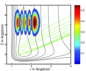
The task is to find the initial wavepacket on the reactive channel which will lead to desorption of the molecule in the ’th vibrational state. The scheme is based on reversing the reaction e.g. starting from a product wave function representing the desorbing molecule in the ’th vibrational state. This wave function is propagated backwards in time to find the reactive wave function leading to the desired final condition. The scheme is illustrated for an Eley-Rideal reaction in which an impinging lithium atom recombines with an adsorbed hydrogen atom. A trial wave function on the product channel has been constructed. Far enough from the surface the internal and external degrees of freedom are uncoupled. Thus the trial wave packet can be expressed as a product of the ’th molecular vibrational eigenstate, (), and a Gaussian wavefunction, ,
| (4) |
The wavefunction used for control is the wavefunction of a lithium matter wave source. The target is to desorb a lithium hydride molecule in the fifth vibrational state (). A target trial wave function has been constructed according to Eq.3 and is shown in Fig. 1. An iterative scheme is used for inversion i.e. finding the condition for the wavepacket on the reactant channel leading to desorption of the molecules in the ’th vibrational state.
-
1.
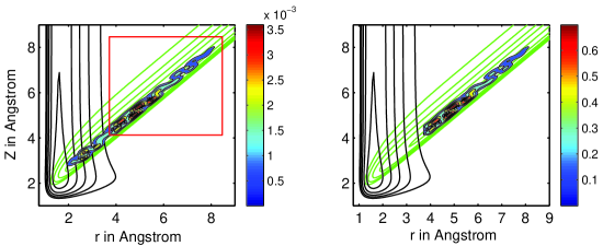
Backward propagation: A trial wave function is propagated backward in time. As the molecule approaches the surface population is transferred to the reactant channel through the non-adiabatic coupling. The part of the wave packet which is transferred to the reactant channel corresponds to a molecular dissociation. That is one atom is chemisorbed on surface and the other desorbing to the gas phase. After a preassigned time the propagation is stopped, leading to the wave function . Fig. 2 (left) shows a wave packet in the reactant channel after termination of the backward time propagation.
-
2.
Selection: Part of the backward propagating wave function, is selected consisting of a wavefunction outside the interaction region. In Fig. 2 (left) the wave function is shown before selection. The part of the wave function which is inside the red box has been selected to resemble the wave function of the reactive channel. The selected wave function is renormalized and it is shown in Fig. 2 (right). The size and location of the box is chosen such that the energy of the selected and normalized wavepacket is close to the energy of the trial wavepacket.
-
3.
Forward propagation: The selected wavefunction, , is propagated forward in time. Through the non-adiabatic coupling between two potential energy surfaces. The newly formed molecules desorbs leading to the wavefunction .
-
4.
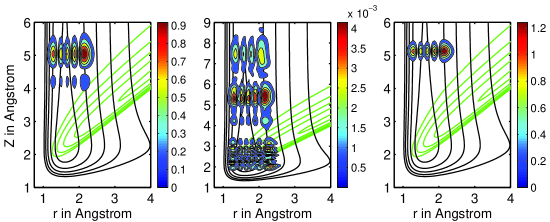
Projection: The overlap between the forward propagated wave function, , and the trial wavefunction is evaluated as a function of the center of mass
(5) A new trial wavefunction is created
(6) In the first iteration is . This new wave function is renormalized and it is used as a new trial wave function in step 1 . The projection of the forward propagated wave packet is illustrated in Fig. 3.
The above pulse shaping scheme is repeated a number of times. It is important that the energy of the total system is conserved after either the selection stage or projection of the total wave function. The pulse shaping algorithm is stopped when a satisfactory yield in the desired vibrational state has been reached. The ultimate goal is that all the flux of desorbing molecules is probed into the particular vibrational state. In order to improve the convergence of the algorithm the number of grid points has been enlarged (10241024) and the grid spacing has been reduced (0.05a.u.) compared to the earlier 2PACC calculationsJørgensen and Kosloff (2003b). The potential energy surfaces are given in Ref.Jørgensen and Kosloff (2003b), where the non-adiabatic coupling term was increased to 0.1eV. The backward propagation is stopped when the non-adiabatic population transfer is negligible. The size and location of the box used for selecting the wave packet in step 2 vary from iteration to iteration in order to keep the reactive wavepacket inside the box. The forward propagation is terminated when the overlap between the trial wavefunction and the propagated wavefunction is maximized.
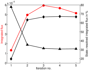
Starting from the trial wavefunction of Fig. 1 the pulse shaping scheme was used to obtain the optimal wavepacket in the reactant channel leading to desorption of the molecule in the fifth vibrational state. Fig. 5 shows the accumulated flux of desorbing molecules as a function of the iteration number. State-resolving the accumulated flux enables to calculate the percentage of desorbing molecules in the fourth and fifth vibrational states Cf. Fig. 5. A monotonic increase of the yield in is observed.
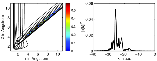
The optimal reactant wavefunction is shown in Fig. 4 (left). The wave function of the matter wave is projected out for the equilibrium distance between the chemisorbed atom and the surface (0.916Å). The 1D wave packet is found to be multi-pulsed reconfirming previous studies, that control is obtained by destructive or constructive quantum interferences. The momentum representation is obtained by performing a Fourier transform of the one-dimension matter-wave. The momentum components are shown in Fig. 4. Several momentum components can be observed which are needed for creating the necessary constructive quantum interference in the fifth vibrational state and destructive in all the other vibrational states.
The source of the matter-waves, the BEC condensate, has to be positioned very close to a surface. Such a device is realized in the so-called atom chipsSchneider et al. (2003); Jones et al. (2003); Folman et al. (2002); Hänsel et al. (2001) or surface micro-trapsLeanhardt et al. (2002); Ott et al. (2001). In the atom chips for example the BEC has been placed a few hundred microns above a metal surfaceFolman et al. (2002).
The experimental realization of the control scheme depends on the the ability to shape matter-waves. Four-wave mixingDeng et al. (1999) of matter waves has been demonstrated which can lead to different momentum components of the matter-waves. A more comprehensive solution could follow ideas from optical pulse shaping. A matter-wave diffraction grid has been demonstratedHornberger et al. (2003); Doak et al. (1999). A setup of two diffraction grids and a phase shift device would constitute the ultimate matter-wave pulse shaper. Such a device would make the suggested control scheme realizable.
SJ thanks Marie Curie Fellowship Organization. This work was supported by the Israel Science Foundation and the European Research and Training Network Cold Molecules: Formation, Trapping and Dynamics. The Fritz Haber Center is supported by the Minerva Gesellschaft für die Forschung, GmbH München, Germany.
References
- Mewes et al. (1997) M.-O. Mewes, M. R. Andrews, D. M. Kurn, D. S. Durfee, C. G. Townsend, and W. Ketterle, Phys. Rev. Lett. 78, 582 (1997).
- Anderson and Kasevich (1998) B. P. Anderson and M. A. Kasevich, Science 282, 1686 (1998).
- Hagley et al. (1999) E. W. Hagley, L. Deng, M. Kozuma, J. Wen, K. Helmerson, S. L. Rolston, and W. D. Phillips, Science 283, 1706 (1999).
- Bloch et al. (1999) I. Bloch, T. W. Hänsch, and T. Esslinger, Phys. Rev. Lett. 82, 3008 (1999).
- Jørgensen and Kosloff (2003a) S. Jørgensen and R. Kosloff, Surf. Sci. 528, 156 (2003a).
- Jørgensen and Kosloff (2003b) S. Jørgensen and R. Kosloff, J. Chem. Phys. 119, 149 (2003b).
- Shi and Rabitz (1990) S. Shi and H. Rabitz, J. Chem. Phys. 92, 364 (1990).
- Hornung et al. (2001) T. Hornung, M. Motzkus, and R. de Vivie-Riedle, J. Chem. Phys. 115, 3105 (2001).
- Palao and Kosloff (2002) J. P. Palao and R. Kosloff, Phys. Rev. Lett. 89, 188501 (2002).
- R. Kosloff, S. A. Rice, P. Gaspard, S. Tersigni and D. Tannor (1989) R. Kosloff, S. A. Rice, P. Gaspard, S. Tersigni and D. Tannor, Chem. Phys. 139, 201 (1989).
- Kosloff (1994) R. Kosloff, Annu. Rev. Phys. Chem. 45, 145 (1994).
- Schneider et al. (2003) S. Schneider, A. Kasper, C. vom Hagen, M. Bartenstein, B. Engeser, T. Schumm, I. Bar-Joseph, R. Folman, L. Feenstra, and J. Schmiedmayer, Phys. Rev. A 67, 023612 (2003).
- Jones et al. (2003) M. P. A. Jones, C. J. Vale, D. Sahagun, B. V. Hall, and E. A. Hinds, Phys. Rev. Lett. 91, 080401 (2003).
- Folman et al. (2002) R. Folman, P. Krüger, C. Henkel, and J. Schmiedmayer, Adv. Atom. Mol. Opt. Phys 48, 263 (2002).
- Hänsel et al. (2001) W. Hänsel, P. Hommelhoff, T. W. Hänsch, and J. Reichel, Nature 413, 498 (2001).
- Leanhardt et al. (2002) A. E. Leanhardt, A. P. Chikkatur, D. Kielpinski, Y. Shin, T. L. Gustavson, W. Ketterle, and D. E. Pritchard, Phys. Rev. Lett. 89, 040401 (2002).
- Ott et al. (2001) H. Ott, J. Fortágh, G. Schlotterbeck, A. Grossmann, and C. Zimmermann, Phys. Rev. Lett. 87, 230401 (2001).
- Deng et al. (1999) L. Deng, E. W. Hagley, J. Wen, M. Trippenbach, Y. Band, P. S. Julienne, J. E. Simsarian, K. Helmerson, S. L. Rolston, and W. D. Phillips, Nature 398, 218 (1999).
- Hornberger et al. (2003) K. Hornberger, S. Uttenthaler, B. Brezger, L. Hackermüler, M. Arndt, and A. Zeilinger, Phys. Rev. Lett. 90, 160401 (2003).
- Doak et al. (1999) R. B. Doak, R. E. Grisenti, S. Rehbein, G. Schmahl, J. P. Toennies, and C. Wö, Phys. Rev. Lett. 83, 4229 (1999).