Proposal for a simple quantum error correction test gate in linear optics
Abstract
We describe a linear quantum optical circuit capable of demonstrating a simple quantum error correction code in a four photon experiment.
I Introduction
Whilst high hopes are held for the eventual demonstration of large scale quantum processing, present experimental attention remains fixed on few qubit demonstrations. Implementation of few qubit algorithms in the competing platforms provides valuable insight into the important physics and technical issues of different architectures.
A relatively new contender for scalable quantum computation is the scheme due to Knill et al KLM based on single photon, dual rail qubits; linear optical networks; and photon resolving measurement and feedforward. Simple gates based on this scheme have been demonstrated pit02 and more general gates are planned ral01 ; pit01 ; ral02 . It is thus timely to consider what small scale circuits might be possible with the currently available technology.
A key enabling quantum circuit is error correction shor95 ; ste96 . Even medium scale quantum processing is expected to be impossible without error correction. Here we describe a simple example of error correction which would suit demonstration with a linear optical circuit. In its simplest form the experiment would require only three coincident photons.
II The Circuit
The quantum circuit we wish to consider is a simplification of the standard bit flip correcting code nie00 and is shown in Fig.1. The qubit is encoded with the following relationship between logical, , and physical, , qubits:
| (1) |
We suppose that one of the physical qubits, say the second, suffers decoherence which produces random bit-flips. As a result of this decoherence an arbitrary initial qubit:
| (2) |
evolves into the mixed state:
| (3) | |||||
where is the probability that the bit flip occurred. The aim of the circuit which follows is to return the qubit to its original logical value. To achieve this requires an ancilla photon prepared in the physical zero state. We can write the combined state of the qubits and ancilla after decoherence as

| (4) | |||||
with the subscript “a” labelling the ancilla state. A controlled not (CNOT) gate is applied with the ancilla as target and the first qubit as control. This transforms the state to
| (5) | |||||
A second CNOT is then applied with the ancilla as target but now the second qubit acts as control. The state becomes
| (6) | |||||
Finally we detect the ancilla state. If we find the ancilla in the zero state then the logical qubit is projected onto its original state and no correction is neccessary. On the other hand if the ancilla is found in the one state then the projected state is
| (7) |
We know an error has occurred which can be corrected by flipping the value of the second physical qubit and thus returning the logical qubit to its initial value.
The circuit can also be understood in the language of stabilizer codes got96 . The code space is the eigenstates of , whilst the error space is the eigenstates of . Here is the Pauli sigma z operator and indicates the tensor product of a sigma z measurement on the first qubit with a sigma z measurement on the second qubit. The two CNOT’s achieve precisely this measurement with the ancilla equals zero result indicating the eigenstate, and hence the system being in the code space, while the ancilla equals one result indicates the eigenstate and hence the system is in the error space and needs to be corrected.
The usefulness of this circuit is obviously limited by the very specific nature of the errors corrected, ie only bit flips on one of the physical qubits. Never-the-less it exhibits the same basic structure as more versatile codes nie00 whilst limiting the complexity of the required circuit. In the next section we will discuss an optical implementation of this code which appears tractable to current experimentation.
III The Optical Implementation
We consider single photon qubits with the polarization degree of freedom determining their logical values. We define the physical qubit value “zero” as being a single horizontally polarized photon, , and a physical qubit value of “one” as being a single vertically polarized photon, . Knill et al KLM showed that non-deterministic CNOT gates could be constructed from linear optics with success rates of one in sixteen, using two additional ancilla photons. A CNOT would be required to produce the encoded logical qubits. Thus an implementation of our error correction circuit would require three CNOTs and hence require the simultaneous production of nine single photon states. The success rate would be about one in four thousand. Although not beyond the realm of medium term possibility, such an experiment is currently not feasible. However in the following we will discuss an in principle demonstration utilizing the coincidence basis with much lower technical requirements.
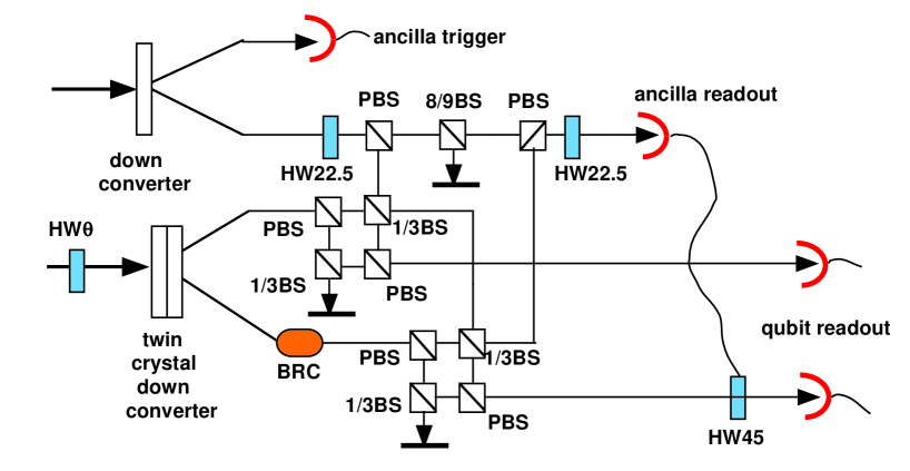
The proposed set up is shown schematically in Fig.2. The encoded state is produced directly using type one down conversion through a pair of crystals with orthogonally oriented optical axes whi99 . Pairs of photons originating from one crystal will be horizontally polarized whilst those originating from the other crystal will be vertically polarized. By changing the polarization of the pump beam the proportion of horizontal to vertical pairs can be continuously varied. In the far field, for sufficiently thin crystals, spatial information on the origin of the pairs is erased and the resulting entangled output state is approximately
| (8) |
where is the vacuum state, and , label the two beams, and and is the orientation of the pump beam polarization away from vertical. Coincidence detection will pick out only the doubly occupied parts of the state, so the effective input state is
| (9) |
which is logically identical to Eq.2.
Controlled decoherence can be introduced onto the second qubit by passing it through a birefringent crystal oriented at degrees to horizontal jam01 . The effect of the crystal is to pull apart in time the two polarization modes in the diagonal/anti-diagonal basis. When the time difference becomes an appreciable fraction of the coherence length decoherence occurs. In the horizontal/vertical basis the resut is random bit flips and the state produced can be written in the form of Eq.3. The degree of decoherence, , is a function of the crystal length.
To detect the errors we must introduce an additional ancilla qubit for readout. This can be supplied by a second down-converter producing just horizontal pairs. A CNOT gate which works in the coincidence basis and does not require additional ancilla modes can be implemented using just linear optics ral02 ; hof02 . The schematic of Fig.2 shows the optical network needed to implement the two CNOT’s in the quantum circuit (Fig.1). The polarization qubits are decomposed into separate spatial modes using polarizing beamsplitters then the modes from different qubits are mixed on beamsplitters. Many optical paths are possible through the network but only a few result in photonic qubits at all three outputs, as determined by coincident detection of photons. In such cases quantum interference due to indistinguishability of photons ensures the required transformations are implemented. The success rate is one in eight-one.
Correction of the decohered qubit could be implemented, if required by the result of the ancilla detection, using a fast Pockel cell pit02b .
For most runs of the experiment insufficient photons will be detected and we have a null result. However, on those occasions when a photon is detected at the ancilla trigger and at the ancilla output, and photons are detected at both qubit outputs, then to an excellent approximation the quantum circuit of Fig.1 will have been implemented. For such event we would expect the logical value of the qubits should ideally be the same as that prepared, in spite of the presence of the decohering element.
Four photon coincidences of a few per minute have been achieved with down conversion bou02 . This will be further reduced by a factor of one in eighty-one for this proposal. On the other hand working in the coincidence basis means, at least in principle, that this source efficiency and the efficiency of the detectors does not effect the fidelity of the accepted events.
IV Conclusion
We have described a simple error correction code, and proposed an in principle test of its operation using current four-photon technology. Although both the code and its implementation are major simplifications over what would be required in a scalable architecture, many of the basic principles are common. We thus suggest that pursuit of experiments like the one proposed here will reveal much about the important physical and technical issues to be faced for truly scalable architectures.
Acknowledgements.
We thank Charlene Ahn and Gerard Milburn for motivating discussions. This work was supported by the Australian Research Council and ARDA.References
- (1) “A scheme for efficient quantum computing with linear optics”, E. Knill, R. Laflamme and G. Milburn, Nature 409, 46-52, (2001).
- (2) “Demonstration of Nondeterministic Quantum Logic Operations Using Linear Optical Elements”, T. B. Pittman, B. C. Jacobs, J. D. Franson, Phys. Rev. Lett. 88, 257902 (2002).
- (3) “Simple scheme for efficient linear optics quantum gates”, T. C. Ralph, A. G. White, W. J. Munro and G. J. Milburn, Phys. Rev. A65, 012314 (2002).
- (4) “Probabilistic quantum logic operations using polarizing beam splitters”, T. B. Pittman, B. C. Jacobs, J. D. Franson, Phys. Rev. A64, 062311 (2001).
- (5) “Linear optical controlled-NOT gate in the coincidence basis”, T. C. Ralph,, N. K. Langford, T. B. Bell, and A. G. White, Phys. Rev. A65, 062324 (2002).
- (6) “Scheme for reducing decoherence in quantum computer memory”, P. Shor, Phys. Rev. A52, 2493-2496 (1995).
- (7) “Error correcting codes in quantum theory”, A. M. Steane, Phys. Rev. Lett. 77, 793-797 (1996).
- (8) M. Nielsen and I. Chuang, Quantum computation and quantum information (Cambridge University Press, Cambridge, UK 2000).
- (9) “Class of quantum error correcting codes saturating the quantum Hamming bound”, D. Gottesman, Phys. Rev. A54, 1862-1868 (1996).
- (10) “Nonmaximally Entangled States: Production, Characterization, and Utilization”, A. G. White, D. F. V. James, P. H. Eberhard, and P. G. Kwiat Phys. Rev. Lett. 83, 3103-3107 (1999).
- (11) “Measurement of qubits” D. F. V. James, P. G. Kwiat, W. J. Munro, and A. G. White Phys. Rev. A64, 052312 (2001).
- (12) “Quantum phase gate for photonic qubits using only beam splitters and postselection”, H. F. Hofmann, S. Takeuchi, Phys. Rev. A66, 024308 (2002).
- (13) “Demonstration of feed-forward control for linear optics quantum computation”, T. B. Pittman, B. C. Jacobs, J. D. Franson, Phys. Rev. A66, 052305 (2002).
- (14) “Multiphoton entanglement”, M. Bourennane, M. Eibl, S. Gaertner, N. Kiesel, C. Kurtsiefer, M. Zukowski and H. Weinfurter, Proceedings of SPIE 4917, 45-53 (2002).