Fast and robust two–qubit gates for scalable ion trap quantum computing
Abstract
We propose a new concept for a two–qubit gate operating on a pair of trapped ions based on laser coherent control techniques. The gate is insensitive to the temperature of the ions, works also outside the Lamb–Dicke regime, requires no individual addressing by lasers, and can be orders of magnitude faster than the trap period.
Trapped ions constitute one of the most promising systems to implement scalable quantum computation. PhysicsTodayMay2003 In an ion trap quantum computer qubits are stored in long-lived internal atomic states. A universal set of single and two qubit gates is obtained by manipulating the internal states with lasers, and entangling the ions via the motional states CiracZoller1 . During the last years a remarkable experimental progress in building an ion trap quantum computer has allowed to realize two–qubit gates Wineland95 ; Wineland1 ; Wineland2 ; Blatt and also to prepare entangled states Wineland3 ; Wineland4 ; Wineland5 . The ultimate challenge is now the development of scalable ion trap quantum computing. Scalability is based on storing a set of ions, and moving ions independently, in particular to bring together pairs of ions to perform a two-qubit gate Scalable-a ; Scalable-b . Basic steps towards this goal have already been demonstrated experimentally papermotionWineland .
An important question to be addressed is to identify the current limitations of the two–qubit gates with trapped ions (given the fact that one–qubit gates are significantly simpler with those systems). The ideal scheme should: (i) be independent of temperature (so that one does not need to cool the ions to their ground state after they are moved to or from their storage area); (ii) require no addressability (to allow the ions to be as close as possible during the gate so as to strengthen their interaction), and (iii) be fast (in order to minimize the effects of decoherence during the gate, and to speed up the computation). This last property has been identified PhysicsTodayMay2003 as a key limitation: in essentially all schemes suggested so far CiracZoller1 ; Proposals-b ; Proposals-c ; Proposals-d ; ProposalsMilburn ; Proposals-a one has to resolve spectroscopically the motional sidebands of the ions with the exciting laser, which limits the laser intensity and therefore the gate time.
The two–qubit gate between pairs of ions analyzed below solves the problem of speed by using mechanical effects instead of spectral methods to couple the motion and internal states of the ions. In this way the new limits on the time of the quantum gate are those of laser control, which can be orders of magnitudes faster than the present limits dictated by trap design. Thus, the method proposed here is a significant step forward towards fast and efficient scalable quantum computations with trapped ions.
Below we will first study the dynamics of a pair of trapped ions under the influence of short laser pulses with varying directions. We will prove that there exist certain laser pulse sequences which perform a phase gate on the two qubits, while leaving the motional state unchanged. We illustrate this with two protocols for laser pulses: (i) a sequence of four pulses which gives a gate time of with the trap frequency, and (ii) a protocol which allows us to perform a gate in a time where is the number of laser pulses. Finally, we will complement our study of the gate dynamics with an analysis of possible errors, which includes fluctuations of the intensity or the duration of the pulses, and temperature. The gate will be shown to be extremely robust to these perturbations.
We consider two ions in a one–dimensional harmonic trap, interacting with a laser beam on resonance. The Hamiltonian describing this situationCiracZoller1 can be written as , where describes the motion in the trap and
| (1) | |||||
Here, and are the frequencies of the center of mass and stretching mode, respectively; and are the corresponding annihilation operators, and and are proportional to the Lamb–Dicke parameter, . Note that the Rabi frequency is the same for both ions, since we have not assumed individual addressing. Also notice that replacing with is equivalent to reversing the direction of the laser beam.
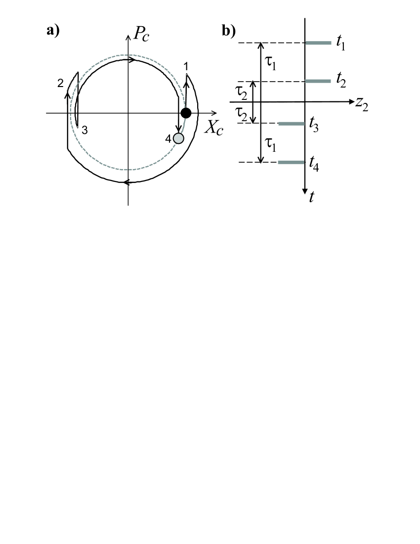
In the following we will consider two different kind of processes: (i) Free evolution, where the laser is switched off () for a certain time; (ii) Sequences of pairs of very fast laser pulses, each of them coming from opposite sides. If we denote by the duration of a pulse and by the corresponding Rabi frequency, we are interested in the limit with . Processes (i) and (ii) will be alternated (See Fig. 1a): at time a sequence of pulses is applied, followed by free evolution until at time another sequence of pulses is applied followed by free evolution and so on. The are integer numbers, whose sign indicates the direction of the laser pulses.
For a pulse sequence, consisting of kicks interspersed with free harmonic time evolution (Fig. 1), we write the evolution operator as , where has contributions of the center–of–mass and relative motions,
The integers indicate the direction of the initial pulse in the sequence of pairs of very fast laser pulses, each of them coming from opposite sites.
In order to fully characterize , we only have to investigate its action on states of the form , where denote the computational basis, and and are coherent states. This task can be easily carried out once we know the action of on an arbitrary coherent state , where
We obtain , where
with .
The crucial point is to realize that if the motional state after the evolution is the same as if there was only free evolution [Fig. 1a], and a global phase appears which does not depend on the motional state. Translating this result to the operators and , we obtain the conditions
| (3a) | |||||
| (3b) | |||||
If these commensurability conditions are satisfied, the motional state of the ion will not depend on the qubits and the evolution operator will be given by
| (4) |
The value is the total time required by the gate and
| (5) |
where . Therefore, if Eqs. (3) are fulfilled, and we will have a controlled–phase gate (which is equivalent to a controlled–NOT gate up to local operations) which is completely independent of the initial motional state, i.e. there are no temperature requirements.
It is straightforward to show that for any value of the time it is always possible to find a sequence of laser pulses which implements the gate, and therefore the gate operation can be, in principle, arbitrarily fast. The search for a sequence of pulses may be done numerically, or even semianalytically. In the following we give two simple protocols which are not optimized in order to reduce the number of pulses.
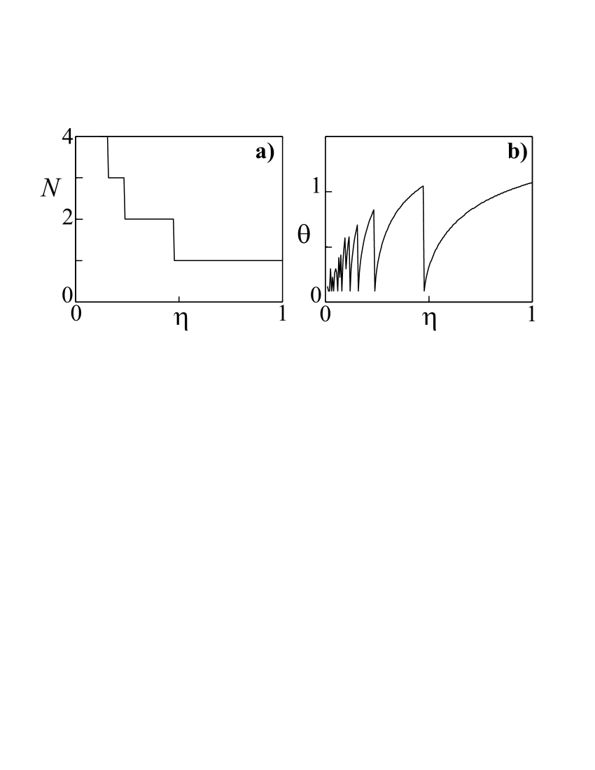
The first protocol (Protocol I) requires the least number of pulses to produce the gate in a fixed time . The recipe is illustrated in Fig. 1, which provides the phase space plots for the evolution of the motional state. The sequence of pulses is defined as . Here is a real number, which may be introduced by tilting both lasers a small angle with respect to the axis of the trap, so that no transverse motion is excited. It is always possible to find a solution to Eq. (3) with . The results for the performance of the gate are summarized in Fig. 2. As shown in Fig. 2(a), for realistic values of the Lamb–Dicke parameter Wineland1 we only need to apply the sequence of pulses one or two times to implement a phase gate.
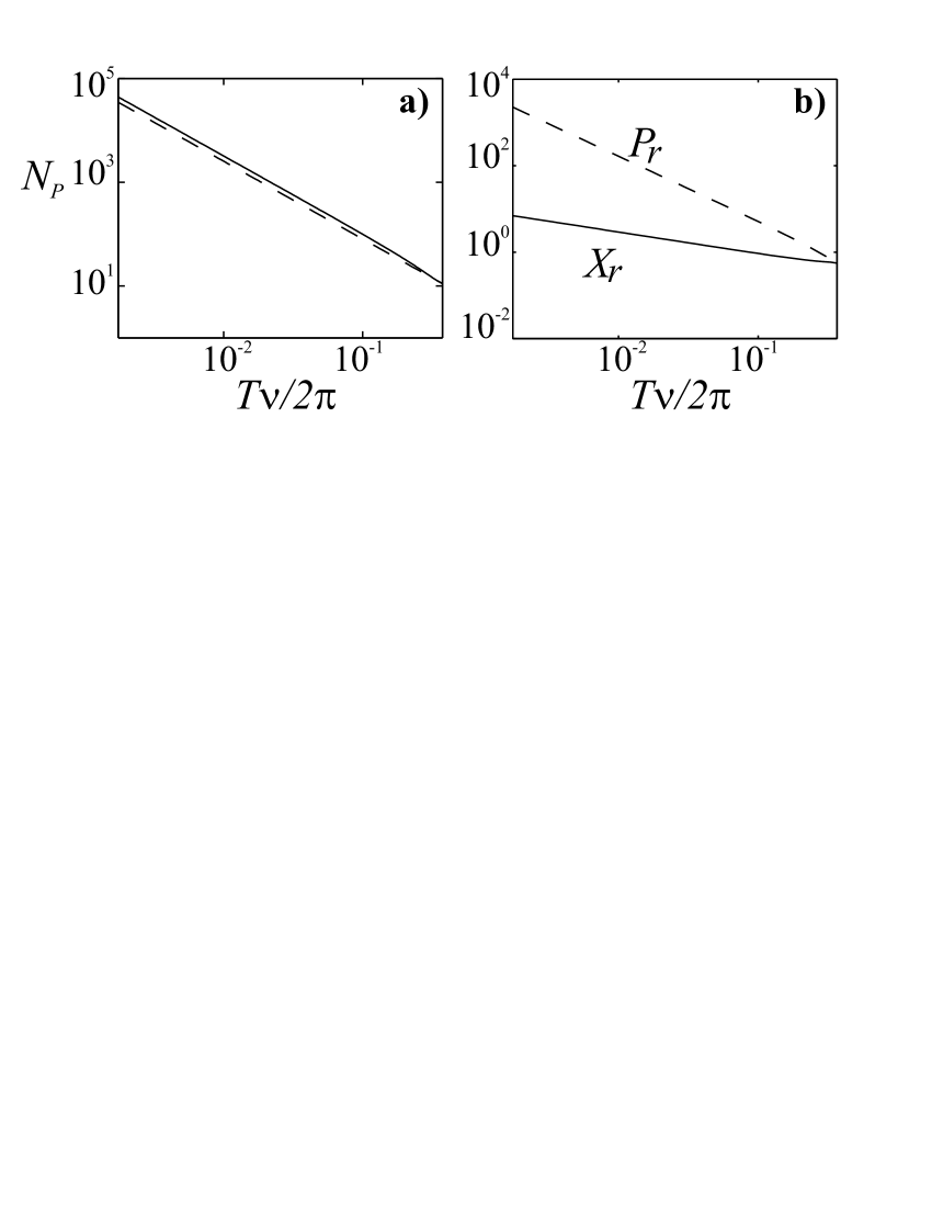
The second protocol (Protocol II) performs the gate in an arbitrarily short time . The pulses are now distributed according to . The whole process takes a time and requires pairs of pulses. As Fig. 2 shows, the number of pulses increases with decreasing time as .
In order to study the main potential limitations of our scheme, we define the error of the gate in terms of the gate fidelity Nielsen as . Here and denote traces over motional and internal degrees of freedom, and depends on , the gate performed in the presence of imperfections.
We now turn to a discussion of the possible sources of errors. A limiting factor for the gate is the anharmonicities of the restoring forces. The more pulses we apply, the larger the relative displacement of the ions, as Fig. 3(b) shows. When the ions become too close to each other, the increasing intensity of the Coulomb force can lead to a breakdown of the harmonic approximation which is implicit in Eq. (1). In order to analyze this effect, we have made a perturbation analysis for and found that such an anharmonicity causes an error , where is the ground state size of the external potential and is the ion separation in equilibrium. For typical parameters and imposing an error we obtain . A similar analysis could be applied to study anharmonicities of the trap itself.
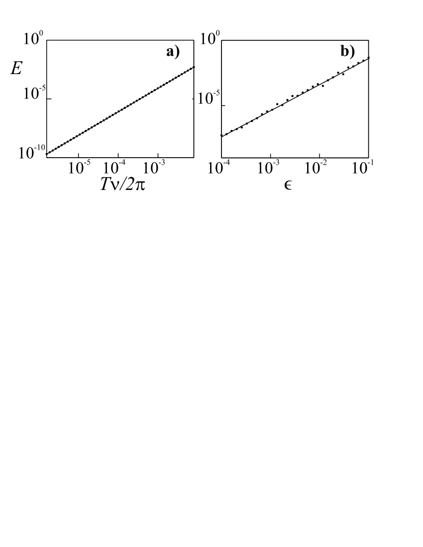
In addition, we have studied the influence of errors in the laser pulses of our scheme. Up to now, our analytical calculations assumed that the intensity of the laser is very large during each pulse, and that therefore one may neglect the influence of the trap during this process. To validate this assumption we have simulated numerically a system of two ions with only one vibrational mode. We have used the exact sequences developed above to produce the phase gate using only eight laser pulses. In Fig. 4(a) we plot the error of the gate as a function of the duration of the laser pulse, . The longer the pulse, the more important the effect of the trap, and the larger the error. But even for relatively long pulses, we obtain a fidelity which is comparable to the results obtained in current setups Wineland1 ; Blatt ; Wineland2 . We have also studied the influence of noise in the intensity of the laser pulses, or, what is equivalent, random errors in its duration. The larger the amplitude of the error the lower the fidelity of the gate, as Fig. 4(b) shows.
As mentioned before, the scheme is insensitive to temperature. If the commensurability condition (3) is not perfectly satisfied due to, for example, errors in timing of laser pulses, or misalignment of the lasers, then the corresponding contribution to the gate error is
with
| (6) | |||||
| (7) |
which is a smooth function of temperature .
Finally, we would like to make some remarks regarding the experimental implementation of this scheme. First, it is not necessary to kick the atoms using pairs of counter-propagating laser beams. The same effect (i.e. a change of sign in ) may also be achieved in current experiments by reverting the internal state of both ions simultaneously. One then only needs a laser beam aligned with the trap to kick the atoms, and another laser orthogonal to the axis of the trap to produce the NOT-gate.
The second and more important remark is that it is possible to avoid errors in the laser pulses by using more sophisticated kicking methods. One possibility consists in using STIRAP STIRAP-a ; STIRAP-b . Only one of the qubit states would be connected by two on–resonance laser beams to a third atomic state, . In the first part of the kicking process, the Rabi frequencies of the lasers and are adiabatically switched on an off respectively. The momenta of both laser beams should be different, so that as we slowly proceed from to the opposite regime , the ions in the state are completely transferred to the new dark state and get a kick . Next we must change the sense of the laser beams (), and perform the adiabatic transfer from to . The total transformation will be , . The advantages of this method are: (i) the system remains all the time in a dark state, avoiding spontaneous emission; (ii) the process is insensitive to fluctuations of the intensity; (iii) the duration of the pulse need not be precisely adjusted, and (iv) the intensity of the laser need not be the same for both ions.
Summing up, in this work we have developed a new concept of two-qubit quantum gate for trapped ions, in which the trap frequency poses no longer a limitation on the speed of the gate. Rather than performing sideband transitions which weakly couple the internal and the motional states of the atoms, we suggest to push the atoms resonantly during very short times and along different directions. The limitations in that case come from: (i) the anharmonicities of the restoring force that the ions experience when pushed far away from each other, and (ii) the ability to control the laser pulses. The first limitation still allows to perform the gates in a time which is three orders of magnitude smaller than the one imposed by the trap frequency. The second one can be overcome by using adiabatic passage techniques which make these laser excitations tolerant against laser imperfections. In any case, the rapid experimental progress in laser control with very short pulses indicates that it may be possible soon to perform quantum gates with a very high speed. In addition, our scheme is independent of the temperature, requires no addressability, and works beyond the Lamb-Dicke regime.
J.I.C. thanks D. Leibfried for discussions and NIST for the hospitality during his stay in Boulder. P.Z. thanks the Innsbruck ion trap group for discussions. Part of this work was supported by the EU IST project RESQ, the project TOPQIP, the DFG (Schwerpunktprogramm Quanteninformationsverarbeitung) and the Kompetenznetzwerk Quanteninformationsverarbeitung der Bayerischen Staatsregierung. Research at the University of Innsbruck is supported by the Austrian Science Foundation, EU Networks and the Institute for Quantum Information.
References
- (1) B. G. Levi, Physics Today (2003).
- (2) J. I. Cirac, and P. Zoller, Phys. Rev. Lett. 74, 4091 (1995).
- (3) C. Monroe et al., Phys. Rev. Lett. 75, 4714 (1995).
- (4) B. DeMarco et al., Phys. Rev. Lett. 89, 267901 (2002).
- (5) D. Leibfried et al., Nature 422, 412 (2003).
- (6) F. Schmidt–Kaler et al., Nature 422, 408 (2003).
- (7) Q. A. Turchette et al., Phys. Rev. Lett. 81, 3631 (1998).
- (8) V. Meyer et al., Phys. Rev. Lett. 86, 5870 (2001).
- (9) C. A. Sackett et al., Nature 404, 256 (2000).
- (10) J. I. Cirac, and P. Zoller, Nature 404, 579 (2000).
- (11) D. Kielpinksi, C. Monroe, and D. J. Wineland, Nature 417, 709 (2002).
- (12) M. A. Rowe, et al., Quantum Inf. and Comp. 2, 257 (2002).
- (13) A. Sørensen and K. Mølmer, Phys. Rev. A 62, 022311 (2000).
- (14) A. Sørensen, and K. Mølmer, Phys. Rev. Lett. 82, 1971–1974 (1999).
- (15) D. Jonathan, M. B. Plenio, and P. L. Knight, Phys. Rev. A 62, 042307 (2000).
- (16) G. J. Milburn, S. Schneider, and D. F. V. James, Fort. Phys. 48, 801–810 (2000).
- (17) A notable exception is J. F. Poyatos., J. I. Cirac, and P. Zoller, Phys. Rev. Lett. 81, 1322 (1998). However, here highly non–harmonic traps are required and still the gate time is limited by the trap frequency.
- (18) M. A. Nielsen, and I. L. Chuang, Quantum Computation and Quantum information (Cambridge Univ. Press, Cambridge, 2000).
- (19) M. Weitz, B. C. Young, and S. Chu, Phys. Rev. A 50, 2438 (1993).
- (20) K. Bergmann, H. Theuer, and B. W. Shore, Rev. Mod. Phys. 70, 1003 (1998).