Optomechanical characterization of acoustic modes in a mirror
Abstract
We present an experimental study of the internal mechanical vibration modes of a mirror. We determine the frequency repartition of acoustic resonances via a spectral analysis of the Brownian motion of the mirror, and the spatial profile of the acoustic modes by monitoring their mechanical response to a resonant radiation pressure force swept across the mirror surface. We have applied this technique to mirrors with cylindrical and plano-convex geometries, and compared the experimental results to theoretical predictions. We have in particular observed the gaussian modes predicted for plano-convex mirrors.
pacs:
42.50.Lc, 04.80.Nn, 05.40.JcI Introduction
Mirror thermal noise is a limitation for the sensitivity in many optical precision measurements such as in gravitational-wave interferometers saulson ; brada ; abra , and is an important issue on the way to the Standard Quantum Limit of displacement measurement caves ; jeakel ; bragi . Deformations of the mirror surface due to the thermal excitation of internal acoustic modes strongly depend on the substrate geometry. The resulting noise has been theoretically studied either by a decomposition of the motion over the acoustic modes bondu ; gillespie or by a direct application of the fluctuations-dissipation theorem hello ; levin .
Some experiments are currently under way in the gravitational-wave community, both for the internal thermal noise LFF , and for the pendulum thermal noise Slagmolen ; Leonhardt . They are all of the “direct approach” kind: they aim at directly measuring the off-resonance thermal noise seen by the light through the phase fluctuations of the field reflected by a cavity with the mirror under study. Such tabletop experiments have to deal with two difficulties: they have to work with a sufficient sensitivity in the frequency band of interest, which explains why results are up to now only available for the related photothermal noise BraginskyPhoto ; CerdonioPinard , where the effect can be enhanced by modulating the laser intensity DeRosa ; Rao . They must also use an optical waist not too small as compared to the ones of kilometer-sized interferometers brada ; abra . These two limitations are troublesome since the transposition of the measured noise levels to more realistic experimental conditions is far from trivial saulson ; Gonzalez ; Kajima ; Ohishi .
We present here an experiment on the “normal mode approach” side. Our setup hadjar ; exp1 ; exp2 allows one to check for the accurate optomechanical characteristics of every mechanical resonance of the mirror, including individual quality factor and spatial profile. Such a detailed knowledge rules out objections of the second kind. Applied to mirrors with a cylindrical geometry, it should help in estimating the thermal noise level sensed by the light in interferometers, where this particular geometry is used. It also allows one to investigate the low-frequency optomechanical behavior of mirror for quantum optics purposes, by summing the accurate contributions of all acoustic modes. It is of great interest for mirrors with the plano-convex geometry, where confined acoustic modes with a high quality factor may enhance the coupling with light and could be a tool for the experimental demonstration of quantum effects of radiation pressure caves ; jeakel ; bragi ; pinard .
II Internal modes of a mirror
A light beam reflected on a moving mirror experiences a phase shift proportional to the mirror displacement. One can take advantage of this effect to detect displacements of the mirror with a very high sensitivity. These displacements may be due to the propagation of acoustic waves in the substrate which induces a deformation of its surface, or to a global displacement of the mirror, due for example to the excitation of pendulum modes for a suspended mirror. Both internal bondu ; hadjar ; gillespie ; exp1 ; exp2 and external tittonen ; dorsel modes have an equivalent effect on the phase shift of the light reflected by the mirror. Since external degrees of freedom strongly depend on the clamping of the mirror, they are not considered in this paper. They usually have low resonance frequencies and can easily be experimentally distinguished from internal modes.
The propagation of the internal deformation in the mirror bulk is ruled by the elasticity equation elastic ,
| (1) |
where is the density of the material, and its Lamé constants. One can search for solutions of the form , where is the evolution frequency of the acoustic wave. Solutions of eq. (1) satisfying boundary conditions exist only for discrete frequencies , and provide an orthogonal basis of normal modes of vibration.
Any displacement can be decomposed as a sum over all modes,
| (2) |
The amplitude depends on the force applied on the mirror. If denotes the force by unit surface, the Hamilton equations give an evolution of equivalent to the one of a forced harmonic oscillator pinard ,
| (3) |
where is the effective mass of the mode, proportional to the volume of the mode inside the mirror, and where the brackets stand for the spatial overlap over the mirror surface,
| (4) |
The Fourier component is deduced from eq. (3),
| (5) |
where is the effective susceptibility of mode defined as,
| (6) |
is similar to the susceptibility of a harmonic oscillator without dissipation, of resonance frequency and mass . As shown by eqs. (2) and (5), the motion of the mirror is the superposition of the responses of harmonic oscillators forced by the spatial overlap between the force applied on the mirror and the modes.
The coupling of the mirror with a thermal bath is described by Langevin forces and dampings which appear as additional imaginary parts in the mechanical susceptibilities . These are then similar to the ones of damped harmonic oscillators,
| (7) |
where is the loss angle of the mode, related to the damping rate by,
| (8) |
The evolution of the amplitude [eq. (5)] now becomes,
| (9) |
The Langevin forces are independent one from each other and their spectra are related by the fluctuations-dissipation theorem to the dissipative part of the mechanical susceptibility landau ,
| (10) |
where is the Boltzmann constant and the temperature of the thermal bath. Since this noise spectrum is flat in frequency close to the resonance,
| (11) |
one gets from eqs. (9) and (10) a displacement spectrum due to mode which has a lorentzian shape of width . The resulting Brownian motion of the mirror is the superposition of the responses of each acoustic mode to these Langevin forces and presents resonant peaks at each resonance frequency.
III Experimental setup
We first study the internal acoustic modes of a flat Newport SuperMirror coated on a cylindrical substrate made of fused silica. The mirror is -thick with a diameter of and is clamped on its edge at three -shifted points. With a second concave mirror (curvature radius of 1 ) coated on a similar substrate, it provides a high-finesse symmetric Fabry-Perot cavity. The cavity is long and has an optical finesse of 26000.
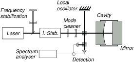
The optical setup hadjar is shown in Fig. 1. A frequency and intensity-stabilized light beam provided by a Titane-Sapphire laser working at is sent into the cavity. A mode cleaner also ensures a spatial filtering of the laser beam. A homodyne detection monitors the phase of the field reflected by the cavity.
For a resonant cavity, the detected signal reflects the global phase-shift experienced by the intracavity field, which can be written as,
| (12) |
where is the optical wavelength, and is the longitudinal mirror displacement averaged over the beam profile bondu ; gillespie ; pinard . The field of the fundamental mode in the cavity is characterized by a transverse gaussian structure at the mirror surface given by,
| (13) |
where is the optical waist. The averaged displacement corresponds to the spatial overlap between the longitudinal mirror displacement and the intensity profile of the light beam,
| (14) |
When no external force is applied on the mirror, the measurement gives the noise spectrum of the displacement due to the thermal noise. From eqs. (2) and (7) to (10) one gets,
| (15) |
where the effective mass is defined by,
| (16) |
For acoustic modes with a characteristic size much larger than the optical waist , the spatial overlap in eq. (16) can be approximated to the longitudinal displacement at the center of the mirror.
Equation (15) shows that the thermal noise spectrum probed by the optomechanical sensor is equivalent to the one of a set of independent harmonic oscillators in thermal equilibrium at temperature , with effective masses related to the coupling between the acoustic modes and the light beam. In particular, for a light beam perfectly centered on the mirror, a mode with a null displacement at the center has an infinite effective mass and does not contribute to the signal.
Optomechanical parameters such as the resonance frequencies , the widthes , and the effective masses can be deduced from the observation of the thermal noise spectrum. It gives no information on the spatial structure of the acoustic modes since the noise spectrum is only sensitive to the displacements at the center of the mirror. The spatial profile can be probed by the response of the mirror to an external force. The experimental setup is then modified as shown in Fig. 2. An intense auxiliary laser beam () is reflected from the back on the mirror. Its intensity is modulated at the resonance frequency of a given mode by an acousto-optic modulator. The beam spot can be deflected in the horizontal and vertical planes by a lens mounted on two motorized micrometric translations. This provides a confined radiation pressure force sweepable over the mirror surface. A demodulation system synchronized with the intensity modulation extracts the amplitude and phase of the mechanical response of the mirror exp2 .
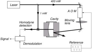
According to eq. (9) the mechanical response is proportional to the overlap of the force with the spatial distribution of the mode. The auxiliary laser beam is focused on the mirror surface with a waist of 100 . The radiation pressure force is thus localized over dimensions small compared to the characteristic size of the modes, and the overlap can be approximated to,
| (17) |
where is the longitudinal displacement at the position of the beam spot on the mirror surface, and is the amplitude of the radiation pressure force. The displacement measured with the homodyne detection is thus proportional to the spatial structure at point .
The motion of the lens is computed in order to move the beam spot along 50 horizontal lines, uniformly distributed along the vertical direction over the mirror surface. For each line, the beam spot is continuously swept from one edge of the mirror to the other one and the amplitude of the displacement modulation is acquired with a digital oscilloscope. The speed of the spot over the surface is set to . Given the time constant of the mechanical response, this speed is slow enough to ensure a spatial resolution better than half a millimeter, way below the expected spatial wavelength of the acoustic modes.
IV cylindrical mirror
We present in this section the characterization of acoustic modes observed for cylindrical mirrors, and we compare the experimental results to a theoretical model developed for this particular geometry hutchi and used in the framework of gravitational-wave detection bondu ; gillespie .
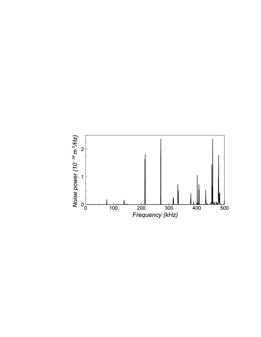
Figure 3 shows the phase-noise spectrum of the reflected beam acquired between and with a resolution bandwidth of . This spectrum reflects the cavity length fluctuations due to the Brownian motion of both mirrors at room temperature. We have performed a calibration of the measured displacements by using a frequency modulation of the laser beam. According to eq. (12), such a modulation changes the length reference given by the wavelength of the laser. A modulation of the optical frequency is thus equivalent to a displacement related to by,
| (18) |
where is the cavity length. We have applied a frequency modulation of with a carrier frequency swept over the whole frequency range of interest (from up to a few megahertz). Monitoring the phase modulation of the reflected beam, equation (18) allows one to calibrate in the measured displacement of the mirror. As shown in Fig. 3, the thermal displacements are of the order of , way above the quantum-limited sensitivity, of the order of hadjar .
The phase-noise spectrum exhibits sharp peaks at each resonance frequency of internal acoustic modes. Their spectral repartition depends on the geometry of the mirror and cannot be analytically computed in the general case. For a cylinder, however, a specific method has been proposed by Hutchinson hutchi , and we use the software Cypres developed by Bondu and Vinet to determine the optomechanical characteristics of the Virgo mirrors bondu . Acoustic modes are classified according to a circumferential order (corresponding to the angular geometry), a parity (equal to 0 for modes having both faces vibrating in phase, and to 1 for those where faces vibrate with opposite phases), and an order number (related to the radial structure).
The computation with Cypres for a -thick cylinder with a diameter of provides a set of frequencies, allowing us to label every peak observed in the experimental thermal spectrum of Fig. 3. Table 1 presents the comparison between the theoretical resonance frequencies (second column) and the experimental ones (third column). Discrepancies between experimental and theoretical values are less than 2%, of the same order of magnitude as the uncertainty on the mirror dimensions. The observation of modes with a non-zero circumferential order , which have no displacement at the center, shows that the laser beam is not perfectly centered on the mirror. This is due to a slight misparallelism between the mirrors of the cavity.
| Mode | Cypres | Exp |
| 0 0 1 | 143 | 146 |
| 0 0 2 | 377 | 379 |
| 0 0 3 | 405 | |
| 0 0 4 | 460 | 457 |
| 0 0 5 | 468 | 465 |
| 0 0 6 | 483 | 483 |
| 0 1 1 | 73 | 75 |
| 0 1 2 | 210 | 213 |
| 0 1 3 | 330 | 332 |
| 0 1 4 | 406 | 408 |
| 0 1 5 | 491 | 494 |
| Mode | Cypres | Exp |
| 1 0 5 | 435 | 432 |
| 1 1 1 | 135 | 138 |
| 1 1 2 | 268 | 270 |
| 1 1 3 | 317 | 316 |
| 1 1 4 | 334 | |
| 1 1 5 | 400 | 402 |
| 1 1 6 | 436 | 437 |
| 1 1 7 | 475 | 478 |
| 2 1 3 | 314 | 315 |
| 2 1 6 | 459 | 460 |
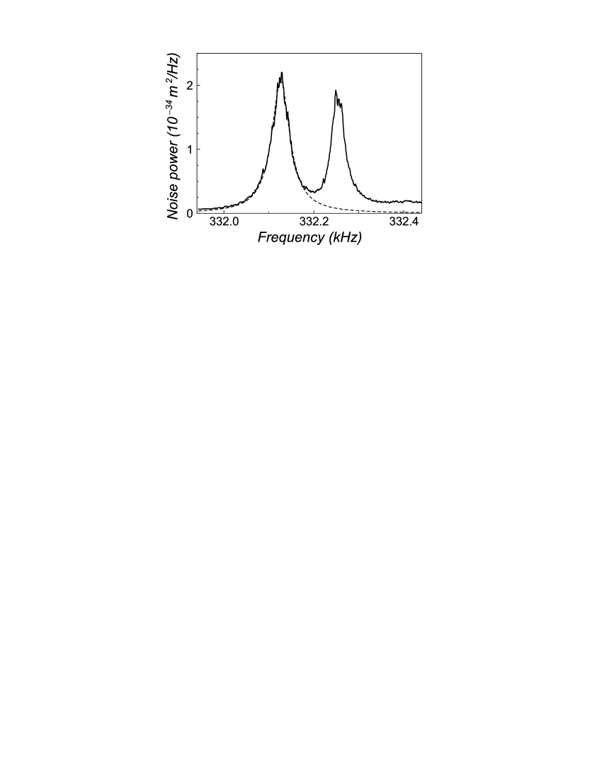
Close to a particular resonance frequency, the mirror motion is mainly ruled by the resonant mode. Figure 4 presents the phase-noise spectrum around with a frequency span reduced to and a resolution bandwidth of . This small resolution bandwidth allows one to resolve the resonance structure, unlike in Fig. 3 where the wider bandwidth broadens and lowers the resonances. The coupling mirror has a concave side, but its curvature radius is much larger than every other dimension so that it can be considered as a cylinder. Both mirrors have thus similar acoustic modes and the spectrum has a twin-peaks structure. The discrepancy between the resonance frequencies of the mirrors is less than 1% for every resonance observed in Fig. 3.
According to eq. (15), the thermal noise spectrum has a lorentzian shape centered at the resonance frequency with a width equal to the relaxation rate and an area proportional to . The dashed line in Fig. 4 is a lorentzian fit of the first peak. It gives a mechanical quality factor equal to for this mode. The quality factor strongly depends on the spatial expansion of the acoustic mode and on the clamping of the mirror. With our three-points clamping, we have obtained quality factors from up to for the various modes presented in Table 1.
The effective mass can be deduced from the area of the lorentzian fit. For modes of Table 1, one gets masses at least 10 times larger than the theoretical ones. This seems to be due to the stress induced by the three-points clamping, while the mirror is assumed to be free in the theoretical derivation. Note also the absence of some modes in Table 1. These modes have a very high theoretical mass (550 for mode ), whereas the typical mass for other modes is a fraction of gram. Their thermal resonances have thus not been seen in the noise spectrum.
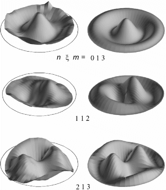
We have studied the spatial distribution of each mode observed in the thermal noise spectrum of Fig. 3, by using the sweepable auxiliary laser beam described in the previous section (Fig. 2). For each mode, the modulation frequency is set to the acoustic resonance frequency, and the beam spot is scanned over the mirror surface. The amplitude of phase modulation of the reflected beam is stored in a computer and plotted in polar coordinates as a function of the beam-spot position. The left part of Fig. 5 shows the result for three modes (, , and ). The solid circle represents the mirror edge. The vertical scale on these plots corresponds to the observed displacements which are of the order of . The right part of Fig. 5 shows the theoretical profiles computed with Cypres. We have obtained a very good agreement between the experimental and theoretical spatial distributions, for every mode presented in Table 1. This is, to our knowledge, the first full experimental demonstration of Hutchinson’s theory.
V plano-convex mirror
In this section we study the acoustic modes of a mirror with a plano-convex geometry. For this particular shape, in the framework of a paraxial approximation, the wave propagation equation (1) has solutions with a gaussian spatial structure wilson ; zarka ; pinard . These modes are confined at the center of the mirror and may have quality factors independent of the mirror clamping.
The end mirror of the cavity is replaced by a mirror coated on the flat side of a plano-convex resonator with a diameter of , a curvature radius of for the convex side, and a thickness at the center of . Hutchinson’s theory is no longer valid for this geometry. We have thus used a finite elements model, based on the ProMechanica software, to determine the resonance frequencies and spatial structures of the acoustic modes. The spatial profile and resonance frequency of the acoustic modes vary continuously when the curvature radius of the convex side varies from infinity (cylindrical mirror) to a finite value (plano-convex mirror). It is then possible to label the acoustic modes of a plano-convex mirror with the same parameters , and . As long as the curvature radius is much larger than the diameter, the discrepancy of frequencies between a cylindrical and a plano-convex mirror is less than a few percents.
First column in Fig. 6 shows the experimental profiles of three acoustic modes observed at , and . The second column presents the theoretical profiles computed with Cypres for a cylindrical mirror of same dimensions. Theoretical resonance frequencies are respectively 1159, 1195, and 1100 . Experimental frequencies and spatial structures are both in very good agreement with theoretical results. These modes present a spatial expansion over the whole surface of the mirror, either via a slowly varying radial profile (mode ), or via multiple oscillations (modes and ). Quality factors for these modes are of the order of only a few tens of thousands.
In parallel with these modes representative of a nearly cylindrical geometry, we have observed confined acoustic modes which are not predicted by Hutchinson’s theory (see Fig. 7). These modes are specific to the plano-convex geometry and can be deduced from a paraxial approximation valid when the curvature radius of the convex side is large compared to the mirror thickness. The propagation equation (1) has solutions similar to the gaussian optical modes of a Fabry-Perot cavity kogel . Within this approximation, shear modes have no longitudinal displacement, and the light beam is only sensitive to compression modes. These modes are labelled by three indexes , , and , and their longitudinal displacements at a point inside the substrate are given by pinard ; wilson ; zarka ,
| (19) | |||||
where is the Laguerre polynomial, the thickness at radial position (equal to for ), and the acoustic waist defined by,
| (20) |
The resonance frequencies are given by,
| (21) |
where is the longitudinal sound velocity. Gaussian modes correspond to series of overtones associated with the longitudinal index . For each overtone, numbers and define the transverse order.
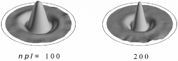
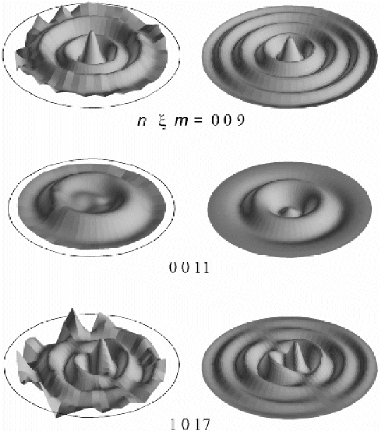
The parameters of our plano-convex mirror lead to a fundamental frequency of . The experimental thermal noise spectrum shows two huge resonances at and . Figure 7 presents the experimental spatial profile of these two modes, which fit well with the fundamental modes of the first two overtones (modes and ). Half-amplitude widthes of the radial profiles give an acoustic waist for the first mode, and for the second, somewhat smaller than the expected values (5.8 and 4.1 , respectively). The ratio is however very close to , in agreement with eq. (20).
The corresponding peaks in the thermal noise spectrum have a width of a few hertz, at the resolution limit of our spectrum analyzer. We have thus measured the mechanical quality factors of both modes by monitoring the response time of the mirror to an external impulsive force resonant with the mode exp1 . We have obtained quality factors of respectively and for these modes. They appear to be much larger than the ones obtained for non-confined acoustic modes. The effective masses of both modes are respectively and , below the expected values ( and ) pinard , and more than 10 times below the experimental effective masses obtained for non-gaussian modes (360 for mode , and 1550 for mode ).
These results can be compared to previous results obtained by x-ray topography with plano-convex resonators wilson ; zarka . In these experiments, the resonator is excited by piezoelectric effect with electrodes deposited on both sides. In our experiment we excite the acoustic modes by a radiation pressure applied on only one side. We thus detect modes of odd overtone as well as those of even overtone, whereas only odd overtones are observed by x-ray topography.
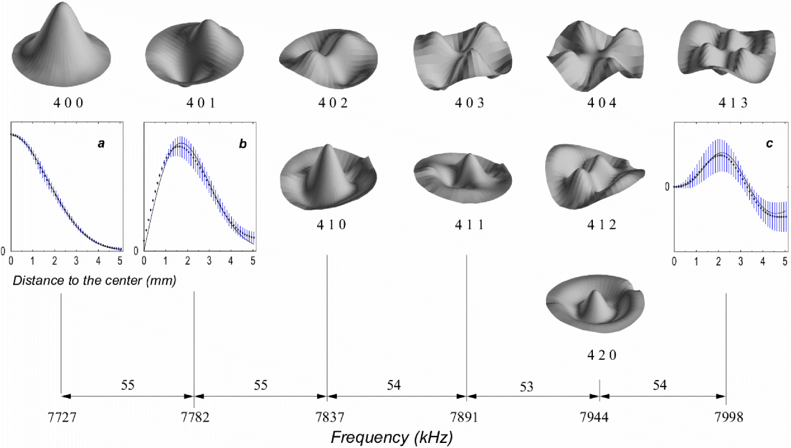
As already observed in Ref. zarka , the experimental profiles fit better and better with the theoretical ones as the overtone number increases and the modes are more confined [see eq. (20)]. The fundamental mode observed in Ref. zarka presents a very noisy profile, whereas modes of third and fifth overtones fit well with a gaussian profile. Figure 8 presents the spatial distributions we obtained for the gaussian modes of the fourth overtone. The plano-convex mirror now has a diameter of , a curvature radius of , and a thickness of 1.55 . The transverse fundamental mode () has a resonance frequency of 7727 , in excellent agreement with the theoretical value (7747 ). The transverse indexes and of a mode can be deduced from the number of zeroes of the radial function and from the cylindrical symmetry of the spatial distribution. This classification shows that the transverse modes have the expected degeneracy. For example, modes , , and have equal frequencies, with an agreement better than 0.5%. The frequency gap between non-degenerate modes is equal to , in good agreement with the theoretical value ().
Knowing the circumferential order of a mode, the radial function can be extracted from the experimental distribution and compared to the theoretical radial dependency given by eq. (19). Inserts , , and in Fig. 8 show the radial profile of different modes. Each experimental point is the angular average of the experimental distribution at a distance from the center, divided by the angular dependence . A gaussian fit of the 4 0 0 mode profile, shown by the solid curve in insert , gives an acoustic waist of , slightly larger than the expected. The other profiles in Fig. 8 are compared with the theoretical radial function (solid lines) using the same experimental value of the waist, without any adjustable parameter.
Finally note that our resonator is made of an isotropic material and has the cylindrical symmetry. We thus find that gaussian modes are well described by the Laguerre polynomials basis, in contrast with the acoustic modes of a vibrating anisotropic plano-convex quartz crystal which present the Hermite polynomials structure wilson .
VI Conclusion
We have performed a high-sensitivity measurement of the optomechanical properties of a mirror. Resonance peaks in the thermal noise spectrum of the mirror displacement allow us to determine the frequencies and quality factors of the acoustic modes of the substrate. We have presented a new technique of spatial analysis of the acoustic modes, using the mirror response to a radiation pressure force. Applied to a cylindrical mirror, this method gives the resonance frequencies and spatial profiles of the acoustic modes, in very good agreement with the theoretical model.
The study of a plano-convex mirror with a large curvature radius reveals a similar behavior, with the same acoustic mode structure as a cylindrical mirror. We have also detected confined modes with a gaussian structure, high mechanical quality factors, and small effective masses. The experimental observation of both kinds of acoustic modes gives a more detailed characterization of the behavior of mirrors with a plano-convex geometry.
These results are of great interest for a better understanding of the mechanical properties of a mirror substrate, either in the framework of gravitational-wave detection where the internal thermal noise of the mirror is a critical issue, or for the demonstration of quantum effects in the optomechanical coupling between light and mirrors.
Acknowledgements.
We gratefully acknowledge Jean-Marie Mackowski for the optical coating of the mirrors, François Bondu and Jean-Yves Vinet for stimulating discussions and for the Cypres program, Luca Taffarello and Olivier Arcizet for helping us with the finite elements computations.References
- (1) P.R. Saulson, Phys. Rev. D 42, 2437 (1990)
- (2) C. Bradaschia et al., Nucl. Instrum. Methods A 289, 518 (1990)
- (3) A. Abramovici et al., Science 256, 32 (1992)
- (4) C.M. Caves, Phys. Rev. D 23, 1693 (1981)
- (5) M.T. Jaekel and S. Reynaud, Europhys. Lett. 13, 301 (1990)
- (6) V.B. Braginsky and F.Ya. Khalili, Quantum Measurement (Cambridge University Press, 1992)
- (7) F. Bondu and J.Y. Vinet, Phys. Lett. A 198, 74 (1995)
- (8) A Gillespie and F. Raab, Phys. Rev. D 52, 577 (1995)
- (9) Y. Levin, Phys. Rev. D 57, 659 (1998)
- (10) F. Bondu, P. Hello, and J.Y. Vinet, Phys. Lett. A 246, 227 (1998)
- (11) L. Bracci et al., Class. Quantum Grav. 19, 1675 (2002)
- (12) B. Slagmolen et al., Class. Quantum Grav. 19, 1683 (2002)
- (13) V. Leonhardt et al., Class. Quantum Grav. 19, 1717 (2002)
- (14) V.B. Braginsky, M.L. Gorodetsky, and S.P. Vyatchanin, Phys. Lett. A 264, 1 (1999)
- (15) M. Cerdonio, L. Conti, A. Heidmann, and M. Pinard, Phys. Rev. D 63, 082003 (2001)
- (16) M. De Rosa, L. Conti, M. Cerdonio, M. Pinard, and F. Marin, Phys. Rev. Lett. 89, 237402 (2002)
- (17) S. Rao, ArXiv: gr-qc/0210029
- (18) G. Gonzalez and P. Saulson, Phys. Lett. A 201, 12 (1995)
- (19) M. Kajima, N. Kusumi, S. Moriwaki, and N. Mio, Phys. Lett. A 264, 251 (1999)
- (20) N. Ohishi, S. Otsuka, K. Kawabe, and K. Tsubono, Phys. Lett. A 266, 228 (2000)
- (21) Y. Hadjar, P.F. Cohadon, C.G. Aminoff, M. Pinard, and A. Heidmann, Europhys. Lett. 47, 545 (1999)
- (22) M. Pinard, P.F. Cohadon, T. Briant, and A. Heidmann, Phys. Rev. A 63, 13808 (2000)
- (23) T. Briant, P.F. Cohadon, M. Pinard, and A. Heidmann, Eur. Phys. J. D 22, 131 (2003)
- (24) M. Pinard, Y. Hadjar, and A. Heidmann, Eur. Phys. J. D 7, 107 (1999)
- (25) I. Tittonen et al., Phys. Rev. A 59, 1038 (1999)
- (26) A. Dorsel et al., Phys. Rev. Lett. 51, 1550 (1983)
- (27) L. Landau and E. Lifshitz, Course of Theoretical Physics: Theory of elasticity (Pergamon, 1958)
- (28) L. Landau and E. Lifshitz, Course of Theoretical Physics: Statistical Physics (Pergamon, 1958), Chap. 12
- (29) J.R. Hutchinson, J. App. Mech. 47, 901 (1980)
- (30) C.J. Wilson, J. Phys. D: Appl. Phys. 7, 2449 (1974)
- (31) J. Détaint, H. Carru, J. Schwartzel, B. Capelle, and A. Zarka, 42nd Annual Frequency Control Symposium (1988)
- (32) H. Kogelnik and T. Li, Appl. Opt. 5, 1550 (1966)