Long-Distance Quantum Communication
with Entangled Photons using Satellites
Abstract
The use of satellites to distribute entangled photon pairs (and single photons) provides a unique solution for long-distance quantum communication networks. This overcomes the principle limitations of Earth-bound technology, i.e. the narrow range of some 100 km provided by optical fiber and terrestrial free-space links.
I Introduction
Quantum entanglement is at the heart of quantum physics Schrodinger35a and at the same time the basis of most quantum communication protocols such as quantum cryptography Ekert91 ; Jennewein00 ; Tittel00 ; Naik00 , quantum dense coding Mattle96a , quantum teleportation Bennett93a or methods to exploit the computational advantages of quantum communication complexity Brassard01 ; Buhrman99 ; Brukner02 . Each of those schemes allows efficient communication and computation beyond the capabilities of classical communication, which makes it attractive as a new emerging quantum information technology. This might lead to the build-up of a global quantum communication network, where the distribution and manipulation of quantum entanglement on a global scale is a central task. However, while the realization of such schemes is routine work in the laboratory, non-trivial problems emerge in long-distance applications. At present, the only suitable system for long-distance quantum communication are photons. Other systems such as atoms or ions are studied thoroughly, however their applicability for quantum communication schemes is presently not feasible within the near future, leaving photons as the only choice for long-distance quantum communication. One of the problems of photon-based schemes is the loss of photons in the quantum channel. This limits the bridgeable distance for single photons to some estimated 100 km in present silica fibers Waks02 ; Gisin02 . In principle, this drawback can eventually be overcome by subdividing the larger distance to be bridged into smaller sections over which entanglement can be teleported. The subsequent application of so-called “entanglement swapping” Zukowski93a may result in transporting of entanglement over long distances. Additionally, to diminish decoherence effects possibly induced by the quantum channel, quantum purification might be applied to eventually implement a full quantum repeater Briegel98a . In fact, the experimental building blocks for a full-scale quantum repeater based on linear optics have been successfully demonstrated over the last years by the realization of teleportation and entanglement swapping Bouwmeester97a ; Pan98a ; Jennewein01 and, only recently, by the implementation of a quantum purification protocol Pan03b . Two related, recent results, both of relevance for long-distance applications, are the demonstration of quantum state teleportation over a distance of several tens of meters Marcikic03 and the first realization of freely propagating teleported qubits Pan03 , which eventually will allow the subsequent use of teleported states. From the present point of view it seems obvious that a full implementation of a quantum repeater is within reach.
Despite those achievements of quantum communication experiments, the distances over which entanglement can be distributed in a single section, i.e. without a quantum repeater in-between, are by far not of a global scale. Experiments based on present fiber technology have demonstrated that entangled photon pairs can be separated by distances ranging from several hundreds of meters up to 10 km Tapster94 ; Tittel98 ; Weihs98 , but no significant improvements are to be expected. On the other hand, optical free-space links could provide a unique solution to this problem since they allow in principle for much larger propagation distances of photons due to the low absorption of the atmosphere in certain wavelengths ranges. Also, the almost non-birefringent character of the atmosphere Buttler98c guarantees the preservation of polarization entanglement to a high degree. Free-space optical links have been studied and successfully implemented already for several years for their application in quantum cryptography based on faint classical laser pulses Buttler98c ; Hughes02 ; Kurtsiefer02 . A next crucial step is the distribution of quantum entanglement via such free space links.
However, terrestrial free-space links suffer from obstruction of objects in the line of sight, from possible severe attenuation due to weather conditions and aerosols Horvath02 and, eventually, from the Earth’s curvature. They are thus limited to rather short distances. To fully exploit the advantages of free-space links, it will be necessary to use space and satellite technology. By transmitting and/or receiving either photons or entangled photon pairs to and/or from a satellite, entanglement can be distributed over truly large distances and thus would allow quantum communication applications on a global scale. Such a scenario looks unrealistic at first sight, but in this paper we will show that the demonstration of quantum communication protocols using satellites is already feasible today. To do so, we will describe possible space scenarios based on entanglement. We then analyze prerequisites to distribute entanglement via satellites, describe experimental scenarios for first proof-of-principle experiments and finally give an outlook on the perspectives of satellite-aided quantum communication.
II Scenarios of Space Experiments
When considering space scenarios that allow the distribution of entangled photon pairs we can distinguish the cases in which a satellite is used to carry either a transmitter of entangled photons, or a receiver, or a relay station to distribute photons to further locations. These scenarios will permit different applications.
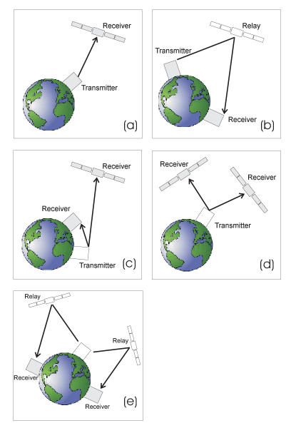
II.1 Earth-based transmitter terminal
The scenarios involving an Earth-based transmitter terminal allow to share quantum entanglement between ground and satellite, between two ground stations or between two satellites and thus to communicate between such terminals employing quantum communication protocols. In the most simple case, a straight uplink to one satellite-based receiver (see Fig. 1 a) can be used to perform secure quantum key distribution between the transmitter station and the receiver. Here, one of the photons of the entangled pair is being detected right at the transmitter site and thus the entangled photon source is used as a triggered source for single photons. If the satellite acts as a relay station (see Fig. 1 b), the same protocol can be established between two distant Earth-based communication parties. Shared entanglement between two parties can be achieved by pointing each of the photons of an entangled pair either towards an Earth-based station and a satellite or towards two separate satellites (see Figs. 1 c and d). Another set of satellite-based relays can be used to further distribute the entangled photons to two ground stations (see Fig. 1 e). Possible applications for shared entanglement between two parties are quantum key distribution or entanglement-enhanced communication protocols Bennett96c .
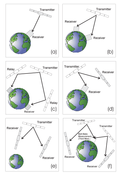
II.2 Space-based transmitter terminal
In a second scenario, a transmitter with an entangled photon source is placed on a space-based platform. This allows not only longer link distances because of reduced influence of atmospheric turbulence (see Appendix B). It will also be the preferred configuration for global quantum communication, since only one downlink per photon of the entangled pair is necessary to share entanglement between two Earth-based receivers. Again, already a simple downlink allows to establish a single-photon link e.g. for quantum cryptography (see Fig. 2 a). In this configuration, a key exchange between two ground stations is also possible. To this end each of the two ground stations has to establish a quantum key with the satellite. Since the space terminal has access to both keys, it can transmit a logical combination of the keys, which can then be used by either ground station or both ground stations such that they arrive at the same key. This logical combination can easily be chosen such that it cannot reveal any information about the key. Note that the key does not have to be generated simultaneously at both receiver stations. In principle, a quantum key exchange can be performed between arbitrarily located ground stations. This is also possible for a ground-based transmitter terminal as shown in Fig. 1 a. However, in all such scenarios based on single photons the security requirement for the transmitter terminal is as high as it is for the ground station. Only the use of entangled states sent to two separate ground stations allows instantaneous key exchange between these two communicating earth-bound parties and also relaxes the security requirement for the transmitter module. Furthermore, more advanced quantum communication schemes will be feasible. The required shared entanglement can be established either by two direct downlinks (Fig. 2 b) or by using additional satellite relay stations (Fig. 2 c). Quantum entanglement can also be distributed between a ground station and a satellite (Fig. 2 d) or between two satellites (Fig. 2 e). In an even more elaborate scheme a third party might be involved, which is capable of performing a Bell-state analysis on two independent photons (Fig. 2 f). This allows quantum state teleportation and even entanglement swapping and could thus resemble a large-scale quantum repeater for a truly global quantum communication network. Applied to quantum cryptography, this third party might be used to control the communication between the two other parties in a ”Third-Man” cryptography protocol. For example in a polarization-based experiment, depending on whether he performs a simple polarization analysis of the independent photons or a Bell-state measurement, the ”Third-Man” can communicate secretly with either of the two parties (or with both) or he can control whether the two can communicate secretly or not without knowing the content of the communication.
II.3 Link requirements
The maximal acceptable link attenuation for a quantum communication system based on entangled photons is determined by the timing resolution and the dark count rates of the detectors used, as well as by the net production rate of the source. As the minimum signal-to-noise ratio we assume that necessary for the violation of a Bell-inequality (see Appendix A). With a typical detection efficiency , a photon production rate of , an estimated total background count rate of and a coincidence timing window of s, the link efficiency should obey
| (1) |
when following the calculations presented in Appendix A. Roughly speaking, a total link efficiency of (60 dB) is necessary.
The link attenuation is also important for determining the number of photon pairs that can be received in a certain time window. This could be crucial in scenarios where the links are only available for short times as is for example the case in uplinks to low orbiting LEO satellites.
III Link Attenuation
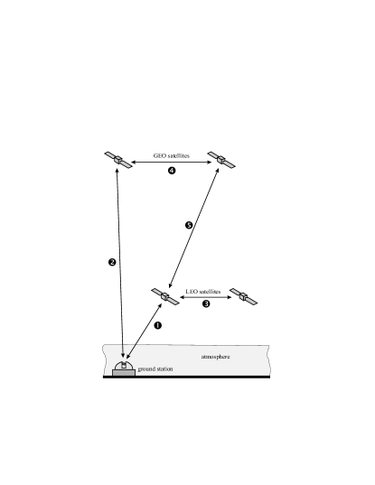
The overall link efficiency of 10-6, corresponding to a maximum attenuation of 60 dB, imposes quite a strong restriction to the various space scenarios. In the following, we will investigate the link attenuation for optical free-space links involving space infrastructure. The attenuation factor calculated includes the effect of beam diffraction, attenuation and turbulence-induced beam spreading caused by the atmosphere, receive aperture diameter, losses within the telescopes acting as antennas, as well as antenna pointing loss. Effects not included in this factor are the detection efficiency of the photon-counter modules (3.5 dB per detector) and reflective and absorptive losses at optical components (typically 3 dB per individual photon link). One may take these losses into account when calculating individual link budgets. Figure 3 summarizes the scenarios considered based on satellites in geostationary orbit (GEO) and in low earth orbit (LEO). Such satellites may serve as a platform for transmitters or receivers. We presently do not envision the use of passive relays, e.g. retro-reflectors or mirrors, because of the high link loss they would introduce and because of the difficulty to implement a point-ahead angle 111The point-ahead angle denotes the difference angle between transmit and receive direction of the telescope. Its occurrence is a consequence of the movement of the satellite together with the finite velocity of light of the signal propagation.
III.1 Satellite–ground links
III.1.1 Ground–LEO or LEO–Ground links
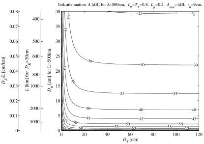
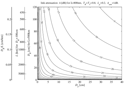
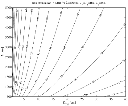
For the case of a LEO-based transmitter or receiver (Link 1 in Fig. 3), link attenuation poses no problems. Even for quite small telescopes onboard the LEO satellite, the attenuation factor is well below for all cases. Figure 4 is a contour plot of the link attenuation as a function of transmitter and receiver aperture diameter (,) for the ground-to-LEO uplinks operated at a wavelength of . Two additional vertical scales give the link distance L for receive telescope aperture as well as for the receive telescope aperture for a link distance of L= (For the equation and further parameters used to arrive at Fig. 4 - and also at some subsequent figures - see Appendix B.). The lines of equal attenuation are separated by . The corresponding plot for LEO-to-ground downlinks is shown in Figure 5. One notes that the attenuation is much larger for the uplink than for the downlink. This is caused by the pronounced influence of atmospheric turbulence for the uplink, where the turbulent layers are close to the transmitter. In contrast, for a downlink the effect of the turbulent layer close to the receiver is negligible to first order. Another consequence of turbulence is that increasing the transmitter aperture for the uplink beyond hardly decreases the link attenuation.
In the case of links connecting a LEO and a ground station the possible duration for communication is comparatively short (e.g. a few minutes) and the angular velocity with which the telescope at the ground station has to be moved to track the satellite along its orbit is high. For all ground-to-space links the possibility of communication is weather dependent. While for clear weather and sufficient altitude of the ground station the uplink attenuation caused by the atmosphere is mainly determined by turbulence-induced beam spread 222For a diffraction limited telescope of diameter and a link distance of , some attenuation have to be expected pfennigbauer02_2 ., clouded skies will make any link impossible. This influence is augmented by the low elevation angles typical for LEO-to-ground links and the thus increased fraction of the propagation path within the atmosphere.
III.1.2 Ground–GEO or GEO–Ground links
III.2 Satellite-satellite links
While from a technological point of view a satellite-to-satellite link is the most demanding configuration it offers highly attractive scientific possibilities. It allows to cover, in principle, arbitrarily large distances and might thus also be a possibility for further novel fundamental tests on quantum entanglement.
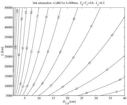
We calculated the attenuation factor as a function of transmitter and receiver aperture diameter for a LEO-LEO link (Link 3 in Fig. 3). Figure 6 displays the attenuation for a wavelength of 800 nm as a function of the satellite distance and telescope diameters and , assumed to be equal for both terminals. We conclude, that the -limit poses no problem for LEO-LEO links with reasonable link distance.
For GEO-GEO links (Link 4 in Fig. 3), the attenuation can be read off Fig. 7, where again equal telescope apertures have been assumed. For a distance of , an attenuation of dB would result for cm.
IV Technological Prerequisites for Entanglement in Space
For performing the quantum communication experiments as described above, the following minimum hardware is required: a transmitter terminal to generate and transmit the entangled particles and one or more receiver terminals suited for single-photon manipulation and detection. Below we briefly outline their main features.
IV.1 Transmitter, receiver and relay modules
A transmitter module comprises a photon source for entangled photon pairs (including passive or active manipulation of single qubit-states), a module for timing synchronization with the receiver station and channel for classical communication. Present entangled photon sources rely on laser-pumped spontaneous parametric down conversion Bouwmeester00 . This technology is very likely capable of being miniaturized to a size suitable for satellite modules.
A receiver module comprises one ore more optical input channels, each of which allows independent manipulation of qubits such as the rotation of photon polarization or the modulation of an interferometric phase. Additionally, it has to be equipped with single-photon detectors at each input port, a receiver module for timing-synchronization, and a classical channel for communication with the transmitter. Depending on whether active (remote) control of optical elements for qubit manipulation is possible or not (via, e.g., a polarizer or a retarder), we distinguish between active and passive receiver modules. Passive manipulation only requires a static setup of linear optics components. Typically, beam splitters in the input ports would randomly distribute incoming photons to differently oriented retarders, polarizers or beam splitters, where a manipulation and successive detection of single photons takes place. This kind of passive receiver module has recently also been suggested by Rarity et al. in a space-suited system for single-photon quantum key distribution Rarity02_1 . For active control of single qubit manipulation, an additional information concerning the arrival time (i.e. a timing synchronization) is required. More advanced quantum communication schemes, such as quantum dense coding or quantum teleportation, require at some stage of the protocol the projection of independent photons in a joint Bell-state, i.e. a Bell-state measurement. Up to now, efficient achievement of this projection is only possible by means of two-particle-interferometry Mattle96a 333Recently, another scheme based on the nonlinear couplings has been suggested to achieve a full discrimination of all four Bell states although with low efficiency Kim01 .This requires that the arrival time difference of two photons at the two input ports of a beam splitter has to be less than their coherence time (typically 0.5 ps) Zukowski95 .
A relay module would redirect and/or manipulate qubit states without actually detecting them. Possibilities for its implementation range from a simple retroreflector to a more sophisticated relay-satellite (e.g. for deep-space communications), where the entanglement of photons establishing the quantum channel between ground station and deep-space satellite could be purified. We emphasize, that a relay can not serve as an amplifier. This is a consequence of the quantum no-cloning theorem Wooters82 .
IV.2 Existing optical space technology
Optical transceivers for space-to-ground links or intersatellite links are almost state of the art. The major design parameters for the transmission sub-system are laser wavelength, modulation format and data rate, and reception technique. Of equal importance is the sub-system required for beam pointing, link acquisition, and automatic mutual terminal tracking (PAT). Because of the very narrow widths of the communication beams involved, PAT asks for highly sophisticated concepts and for electro-mechanic and electro-optic hardware meeting exceptional technological standards. Major parameters entering the link capacity are telescope size, optical transmit power, link distance, and receiver sensitivity. Other aspects are mass, volume, and power consumption of the terminal. Examples for existing space laser communication links include ESA’s intersatellite link SILEX (Semiconductor Laser Intersatellite Link Experiment) and a satellite ground link, which was only recently realized between ARTEMIS and ESA’s optical ground station OGS at Tenerife.
Photon sources and detectors presently implemented in such classical space laser communication systems can, in general, not be directly employed in quantum communication systems. However, the experience available may serve as a starting point for the development of space qualified components needed for quantum space experiments. The available optical communication technology could of course be applied to provide the classical channel that is always necessary in parallel to the quantum channel. One would also make synergistic use of some of the optics employed for PAT and employ one and the same telescope as antenna for both the classical and the quantum channel, which is a novel way of quantum-classical-multiplexing.
IV.3 Proof-of-principle Experiments
The establishment of entanglement in space and, subsequently, its use for fundamental quantum physics experiments and quantum communication applications necessitates certain experimental stages:
Stage I
Creation and detection of qubits (here: single photons) via an optical space link. From an application point of view this achievement would already allow to perform quantum key distribution based on single photons.
Stage II
Establishment of entanglement (i.e. non-classical correlations via shared entangled particles) between the communicating parties. This includes the ability to detect single qubits synchronously at the spatially separated locations of the communicating parties. This stage already allows the most fundamental experiment in quantum physics, the violation of Bell’s inequality. It also makes possible further experiments such as quantum key distribution based on entangled qubits.
Stage III
Bell-state analysis of independent qubits. For the case of photons, the most efficient scheme relies on two-photon interferometry at a beam splitter. Technically speaking, the arrival time of the photonic qubits at the receiver module has to be synchronized such that photon wave-packets overlap at the beam splitter within their coherence length. If this problem is solved, all advanced quantum communication and computation protocols such as quantum state teleportation or quantum dense coding can be implemented.
The selection of an experimental scenario, in which all of these stages can be performed, requires a trade-off between link attenuation and experimental flexibility. It has been shown above that the total link attenuation of the experimental setup must not exceed some , assuming present-day quantum-optics technology. Presently, without the use of quantum memories, entanglement can only be shared when more than one link is available. For the symmetric case of two equally long quantum links (one transmitter and two receivers), this limits the maximal single-link attenuation (between one transmitter and one receiver) to approx. . Although space-to-space links have the attractive advantage of not being influenced by the Earth’s atmosphere, we have to discard them at present due to the expected disproportionate technological and financial effort as compared to alternative schemes with at least one of the communication terminals is on ground. Since two links should be established, it is therefore most reasonable to place the transmitter module in space, while the receiver modules stay in easily accessible ground-based laboratories. Most envisioned quantum experiments require higher flexibility at the receiver due to active polarization control or data analysis. Also, the atmosphere causes a larger footprint in an uplink than in a downlink, due to the higher influence of turbulence. With such perspectives it becomes obvious that in a first proof-of-principle experiment one should place the transmitter module into space and the receiver module(s) on Earth. Because of their relative stationarity, terminals placed on GEO satellites do not require such a highly sophisticated pointing, acquisition and tracking (PAT) systems as those on a LEO satellite. They would also allow for long-duration experiments. On the other hand, the link attenuation and cost are significantly larger for GEO links compared to LEO links. Therefore, when trading GEO-based against LEO-based systems, we would rather accept the more complex PAT system and the limited connection time per orbit and suggest to use a LEO platform for the transmitter terminal for first proof-of-principle experiments.
V Perspectives and limits of space-aided quantum communications
We determined the typical attenuation for the links indicated in Fig. 3. The values listed in Table 1 were calculated using equ. 7 for wavelengths of 800 nm and of 1550 nm, respectively, assuming telescope apertures characteristic for present day optical space technology. The first wavelength seems reasonable because the best single-photon detectors exist for 800 nm, while the second wavelength is mainly used in standard telecom systems. Applying this wavelength may thus increase compatibility and reduce development effort because commercial off-the-shelf components are available. However, the link attenuation is slightly increased for 1550 nm due to the higher absorption in the atmosphere and due to the higher beam divergence at larger wavelength. For each link the default parameters are specified in Appendix C.
Based on present-day technology and assuming reasonable link parameters, it seems feasible to achieve enough entangled photons per receiver pair to demonstrate a quantum communication protocol. For example, assuming a LEO-based transmitter terminal, a simultaneous link to two separate receiving ground stations and a (conservatively estimated) total link attenuation of approx. 444Note again, that in times without quantum memories, quantum entanglement can only be shared when more than one link is available. For the symmetric case, i.e. two equally long quantum links involving one transmitter and two receivers, this limits the maximal single link attenuation between one transmitter and one receiver to approx. 30 dB. Here we assume a loss of for each of the downlinks., one can expect a local count rate of approx. per second in total at each of the receiver terminals. The number of shared entangled photon pairs is then expected to be approx. per second. For a link duration of 300 seconds this accumulates to a net reception of 1200 entangled qubits. One can expect erroneous detection events on the order of 7 per 100 seconds, which yields a bit error of approx. 2%. This would already allow a quantum key distribution protocol between the two receiver stations. It is thus clear, that a demonstration of basic quantum communication protocols based on quantum entanglement can already be achieved today.
|
|
|
|
|
||||||||
|---|---|---|---|---|---|---|---|---|---|---|---|
|
|
|
|||||||||
|
|
|
|
||||||||
|
|
|
|
For the numerical calculation the default parameter values given in Appendix C have been taken. The values within the boxes correspond to a wavelength of , while the others stand for
All proposed setups are based on the utilization of entangled photon pairs as carrier of quantum information. Given state-of-the-art technologies present in today’s quantum optics labs we can specify some practical limitations for the preparation and detection of entangled qubits.
The rate of information transfer is limited by the maximal number of photons or entangled photon pairs that can be created and detected. Typical standard repetition rates for pulsed laser sources able to create (entangled) qubit states are in the order of , which will faint out to only a few thousands per second due to optical filtering, finite coupling efficiency and finite detection efficiency. Additionally one has to take into account transmission losses, which can limit the qubit transmission drastically. Also, state of the art detector systems have low dynamic ranges over a maximum of six orders of magnitude 555The highest dynamic range of about six orders of magnitude is achieved with Si avalanche photodiodes (APDs), whereas systems based on InGaAs up to now reach only three to four orders of magnitude. and a maximal detection rate of some MHz 666Some tens of kHz in the case of InGaAs.. Further development of source and detector technology will lead to additional improvements of the qubit rates.
Besides the possibility of establishing a truly global quantum communication network, space-based distribution of quantum entanglement provides us with additional advantages. On the one hand, quantum communication provides means to establish secure and efficient communication. Space communication links certainly match the category of links that should be secure and efficient for several reasons: at first, satellite remote control is a highly sensitive area with respect to security and, up to now, an unsolved technical problem. Secondly, earth-to-satellite communication not only requires considerable expense but is also only possible within limited time-intervals (e.g. in the case of LEO-satellites). Secondly, resources for communication are rare and/or expensive, since active communication segments in space are specified for low power consumption due to limited power resources; therefore, their potential of communication to other (space- or ground-segments) is strictly limited. Deep space communication is a specific example where communication time is limited and resources are expensive and efficient communication is mandatory. Quantum communication complexity could provide a unique means of information transport with very little consumption of communication resources.
On the other hand, the distribution of quantum entanglement will allow to expand the scale for testing the validity of quantum physics by several orders of magnitude. This is a major challenge for future fundamental experiments in quantum physics.
Appendix A Link requirements
The accidental coincidence rate is given by
| (2) |
where are the dark count rates of the two detectors and is the timing resolution for the electronic registration of a two-fold coincidence event. As the minimum signal to noise ratio we assume that required for violating a Bell-inequality, since this guarantees at the same time the security of certain quantum cryptography schemes Fuchs97 . For the case of polarization-entangled photons this necessitates a two-fold coincidence visibility of at least 71%, corresponding to a signal-to-noise ratio (SNR) of 777The visibility, in terms of the signal and the noise , is defined by .. Below that ratio a local realistic modeling of the observed correlations is possible thus allowing unobserved eavesdropping 888Note, that phase-coded entanglement results in slightly higher requirements to show that no local realistic model describes the corresponding correlations Aerts99 .. Therefore, in order to discriminate the signal from the background coincidences, the minimal observed coincidence rate must be at least 6 times larger than .
The coincidence detection rate is determined by the total coincidence efficiency , which is the product of the individual efficiencies for the two qubit links,
| (3) |
The detected signal coincidences are given by the product
| (4) |
where is the pair production rate of the source and are the detection probabilities. In order to achieve a violation of Bell’s inequality, the signal coincidences must exceed the limit , which leads to the following limit for the total link efficiency
| (5) |
Appendix B Modeling the link attenuation
We define the link attenuation factor as the ratio of the mean transmit and receive power, and reyes02_2 , measured at the entrance and the exit of the transmit and the receive telescope, respectively. Thus losses due to single photon detection efficiency and optical elements such as filters, polarizers or retarders are not included in this number. Then the attenuation factor of a one-way free-space link is thus given by
| (6) |
where is the link distance, the wavelength, and and the diameters of the transmit and receive telescope. With and we denote the transmission factors () of the telescopes, is the pointing loss due misalignment of transmitter and receiver. This basic relationship applies (i) if the receiver is in the transmitter’s far field, i.e. , (ii) if the transmit telescope is diffraction limited, and (iii) if there is no influence of the atmosphere.
Influence of atmosphere
Atmospheric effects on propagation at optical beams can be divided into three categories: absorption, scattering, and turbulence winick86_1 ; andrews98_1 . While absorption and scattering mainly depend on wavelength and visibility conditions, the net impact of atmospheric turbulence additionally depends on elevation angle and direction of transmission fried66_1 . The main effect of atmospheric turbulence is an enlarged beam divergence, resulting in a reduced amount of signal power collected by the receive telescope. Further turbulence-induced effects are beam-wander, loss of coherence, scintillation and pulse distortion and broadening 999Turbulence induced pulse distortion and broadening might actually impose an upper limit to the spectral bandwidth in the pulsed downconversion schemes. Gilbert00 . The effect of turbulence is in general quite different for a space-to-ground link and a ground-to-space link. In a space-to-ground link the light propagates through vacuum for the most of the distance first before being disturbed by the atmosphere, whereas for a ground-to-space link the beam spreading effects of turbulence take place at the beginning of the propagation, causing a strongly enhanced divergence.
Ground-to-space links
For ground-to-space links we therefore modify Equ. 6 to take into account an additional attenuation of the atmosphere and the influence of turbulence. The diffraction-limited divergence caused by the aperture diameter of the transmit telescope is increased when the beam passes turbulent atmosphere. The influence of the atmosphere can be taken into account by the so-called Fried parameter, , which can be interpreted as an “effective aperture” fried66_1 . We will assume that the divergence due to turbulence adds quadratically to the divergence of the telescope pfennigbauer02_2 . The attenuation factor may then be approximated by
| (7) |
where is the attenuation of the atmosphere, given in dB. The divergence angle resulting from the transmit telescope is assumed to be
| (8) |
and the turbulence causes the additional divergence
| (9) |
This calculation probably underestimates the turbulence effect 101010In comparison to the values presented in sodnik00_1 , the divergence obtained with our model is lower by a factor of . However, we do not know the exact turbulence conditions assumed in sodnik00_1 . Also, the experimental results of the ARTEMIS–OGS downlink are slightly worse than our calculations would predict., but our model is considered to be suitable to calculate a lower-bound estimation for the attenuation factor.
Appendix C Default parameters
For the altitude of the LEO satellite we assume 500 km, which thus represents the lower limit of the link distance. For an elevation angle of e.g. 15∘, the link distance is of some 1400 km 111111Note that for low elevation angles the influence of the atmosphere is increased, a fact not taken into account by the model used here..
Geostationary satellites have an altitude of 36 000 km. Again, the link distance may be larger, depending on the elevation of the satellite (for the ARTEMIS-OGS link the link distance is 41 229 km).
The baseline for the ground aperture is 1 m because this is the telescope diameter of ESA’s optical ground station at Tenerife (OGS). Telescopes with a diameter of 20 to 30 cm are small and light enough to be operated even onboard a small LEO satellite. Larger telescopes are feasible, especially for GEO satellites.
We assume the transmission factors , of the involved telescopes to be . The pointing loss is for all links except for the LEO-LEO link, where we assume to take into account the – possibly – high relative velocity of the satellites that might result in reduced tracking accuracy.
The assumption of an atmospheric attenuation of dB applies for excellent sight conditions (no haze, fog, or clouds) and is valid only in certain wavelength regions.
A recently obtained estimate for the Fried parameter, valid for the optical ground station at Tenerife (OGS), is mm for a wavelength of 800 nm in case of weak turbulence pfennigbauer02_2 .
For the calculations presented we have assumed a wavelength of 800 nm and 1550 nm. The following tables summarize the link characteristics.
Table A I: Parameters for ground – LEO and LEO – ground links (default values are underlined)
| link distance | 500 | |
|---|---|---|
| ground aperture | ||
| LEO aperture | ||
| wavelength | , | |
| telescope transmission factor | ||
| pointing loss | ||
| atmospheric attenuation | ||
| Fried parameter |
Table A II: Parameters for Ground – GEO and GEO – Ground links
| link distance | ||
|---|---|---|
| ground aperture | ||
| LEO aperture | ||
| wavelength | , | |
| telescope transmission factor | ||
| pointing loss | ||
| atmospheric attenuation | ||
| Fried parameter |
Table A III: Parameters for LEO – LEO links
| link distance | ||
|---|---|---|
| aperture | ||
| wavelength | , | |
| telescope transmission factor | ||
| pointing loss |
Table A IV: Parameters for LEO – GEO links
| link distance | ||
|---|---|---|
| aperture | ||
| wavelength | , | |
| telescope transmission factor | ||
| pointing loss |
Table A V: Parameters for GEO – GEO links
| link distance | ||
|---|---|---|
| aperture | ||
| wavelength | , | |
| telescope transmission factor | ||
| pointing loss |
Acknowledgment
This paper evolved from a project supported by the European Space Agency under ESTEC/Contract No. 16358/02/NL/SFe, ”Quantum Communications in Space”. We wish to thank Josep Maria Perdigues Armengol for monitoring and supporting this work. We further acknowledge support by the Austrian Science Foundation (FWF) and the Alexander von Humboldt Foundation.
References
- (1) E. Schrödinger, “Die gegenwärtige Situation in der Quantenmechanik,” Naturwissenschaften, vol. 23, pp. 807–812; 823–828; 844–849, 1935.
- (2) A. K. Ekert, “Quantum cryptography based on bell’s theorem,” Phys. Rev. Lett., vol. 67, pp. 661–663, 1991.
- (3) T. Jennewein, C. Simon, G. Weihs, H. Weinfurter, and A. Zeilinger, “Quantum cryptography with entangled photons,” Phys. Rev. Lett., vol. 84, p. 4729, 2000.
- (4) W. Tittel, J. Brendel, H. Zbinden, and N. Gisin, “Quantum cryptography using entangled photons in energy-time bell states,” Phys. Rev. Lett., vol. 84, p. 4737, 2000.
- (5) D. S. Naik, C. G. Peterson, A. G. White, A. J. Berglund, and P. G. Kwiat, “Entangled state quantum cryptography: Eavesdropping on the ekert protocol,” Phys. Rev. Lett., vol. 84, p. 4733, 2000.
- (6) K. Mattle, H. Weinfurter, P. G. Kwiat, and A. Zeilinger, “Dense coding in experimental quantum communication,” Phys. Rev. Lett., vol. 76, no. 25, pp. 4656–4659, 1996.
- (7) C. H. Bennett, G. Brassard, C. Crépeau, R. Jozsa, A. Peres, and W. K.Wootters, “Teleporting an unknown quantum state via dual classical and Einstein-Podolsky-Rosen channels,” Phys. Rev. Lett., vol. 70, no. 13, pp. 1895–1899, 1993.
- (8) G. Brassard, “Quantum communication complexity (a survey),” quant-ph/0101005, 2001.
- (9) H. Buhrman, W. V. Dam, P. Høyer, and A. Tapp, “Multiparty quantum communication complexity,” Phys. Rev. A, vol. 60, pp. 2737–2741, 1999.
- (10) C. Brukner, M. Zukowski, and A. Zeilinger, “Quantum communication complexity protocol with two entangled qutrits,” Phys. Rev. Lett., vol. 89, p. 197901, 2002.
- (11) E. Waks, A. Zeevi, and Y. Yamamoto, “Security of quantum key distribution with entangled photons against individual attacks,” Phys. Rev. A, vol. 65, p. 52310, 2002.
- (12) N. Gisin, G. Ribordy, W. Tittel, and H. Zbinden, “Quantum cryptography,” Rev. Mod. Phys., vol. 74, pp. 145–195, 2002.
- (13) M. Żukowski, A. Zeilinger, M. A. Horne, and A. K. Ekert, ““Event-ready-detectors” Bell experiment via entanglement swapping,” Phys. Rev. Lett., vol. 71, no. 26, pp. 4287–4290, 1993.
- (14) H.-J. Briegel, W. Dür, J. I. Cirac, and P. Zoller, “Quantum repeaters: The role of imperfect local operations in quantum communication,” Phys. Rev. Lett., vol. 81, pp. 5932–5935, 1998.
- (15) D. Bouwmeester, J.-W. Pan, K. Mattle, M. Eibl, H. Weinfurter, and A. Zeilinger, “Experimental quantum teleportation,” Nature, vol. 390, pp. 575–579, 1997.
- (16) J.-W. Pan, D. Bouwmeester, H. Weinfurter, and A. Zeilinger, “Experimental entanglement swapping: Entangling photons that never interacted,” Phys. Rev. Lett., vol. 80, pp. 3891–3894, 1998.
- (17) T. Jennewein, G. Weihs, J.-W. Pan, and A. Zeilinger, “Experimental nonlocality proof of quantum teleportation and entanglement swapping,” Phys. Rev. Lett., vol. 88, p. 17903, 2001.
- (18) J.-W. Pan, S. Gasparoni, R. Ursin, G. Weihs, and A. Zeilinger, “Experimental entanglement purification,” Nature (accepted for publication), 2003.
- (19) I. Marcikic, H. de Riedmatten, W. Tittel, H. Zbinden, and N. Gisin, “Long-distance teleportation of qubits at telecommunication wavelengths,” Nature, vol. 421, p. 509, 2003.
- (20) J.-W. Pan, S. Gasparoni, M. Aspelmeyer, T. Jennewein, and A. Zeilinger, “Freely propagating teleported qubits,” Nature, vol. 421, p. 721, 2003.
- (21) P. R. Tapster, J. G. Rarity, and P. C. M. Owens, “Violation of bell’s inequality over 4 km of optical fiber,” Phys. Rev. Lett., vol. 73, p. 1923, 1994.
- (22) W. Tittel, J. Brendel, H. Zbinden, and N. Gisin, “Violation of bell inequalities by photons more than 10 km apart,” Phys. Rev. Lett., vol. 81, p. 3563, 1998.
- (23) G. Weihs, T. Jennewein, C. Simon, H. Weinfurter, and A. Zeilinger, “Violation of bell’s inequality under strict einstein locality condition,” Phys. Rev. Lett., vol. 81, p. 5039, 1998.
- (24) W. T. Buttler, R. J. Hughes, P. G. Kwiat, S. K. Lamoreaux, G. G. Luther, G. L. Morgan, J. E. Nordholt, C. G. Peterson, and C. M. Simmons, “Practical free-space quantum key distribution over 1 km,” Phys. Rev. Lett., vol. 81, pp. 3283–3286, 1998.
- (25) R. J. Hughes, J. E. Nordholt, D. Derkacs, and C. G. Peterson, “Practical free-space quantum key distribution over 10 km in daylight and at night,” New Journal of Physics, vol. 4, pp. 43.1–43.14, 2002.
- (26) C. Kurtsiefer, P. Zarda, M. Halder, H. Weinfurter, P. Gorman, P. Tapster, and J. Rarity, “A step towards global key distribution,” Nature, vol. 419, p. 450, 2002.
- (27) H. Horvath, L. A. Arboledas, F. J. Olmo, O. Jovanović, M. Gangl, W. Kaller, C. Sánchez, H. Sauerzopf, and S. Seidl, “Optical characteristics of the aerosol in spain and austria and its effect on radiative forcing,” J. Geophys. Res., vol. 107(D19), p. 4386, 2002.
- (28) C. Bennett, C. Fuchs, and J. Smolin, “Entanglement-enhanced classical communication on a noisy quantum channel,” Quantum Communication, Computing, and Measurement (O. Hirota, A.S. Holevo, and C.M. Caves ed.) Plenum, New York (1997) ISBN 0-306-45685-0, pp. 79–88, 1996, eprint quant-ph/9611006.
- (29) D. Bouwmeester, A. Ekert, and A. Zeilinger, Eds., The Physics of Quantum Information. Berlin: Springer-Verlag, 2000.
- (30) J.G.Rarity, P.R.Tasper, P.M.Gorman, and P.Knight, “Ground to satellite secure key exchange using quantum cryptography,” New Journal of Physics, no. 4, pp. 82.1–82.21, 2002.
- (31) M. Zukowski, A. Zeilinger, and H. Weinfurter, “Entangling photons radiated by independent pulsed sources,” in Fundamental Problems in Quantum Theory: A Conference Held in Honor of Professor John A. Wheeler, ser. Annals of the New York Academy of Sciences, D. M. Greenberger and A. Zeilinger, Eds. New York: New York Academy of Sciences, 1995, pp. 91–102.
- (32) W. K. Wooters and W. H. Zurek, “A single quantum cannot be cloned,” Nature, vol. 299, p. 802, 1982.
- (33) C. Fuchs, N. Gisin, R. B. Griffiths, C. S. Niu, and A. Peres, “Optimal eavesdropping in quantum cryptography. i. information bound and optimal strategy,” Phys. Rev. A, vol. 56, pp. 1163–1172, 1997.
- (34) M.Reyes, Z.Sodnik, P.Lopez, A.Alonso, T.Viera, and G.Oppenhäuser, “Preliminary results of the in-orbit test of ARTEMIS with the optical ground station,” in Proc. SPIE, Free-Space Laser Communication Technologies XIV, vol. 4635, January 2002, pp. 38–49.
- (35) K.A.Winick, “Atmospheric turbulence-induced signal fades on optical heterodyne communication links,” Applied Optics, vol. 25, no. 11, pp. 1817–1825, 1986.
- (36) L.C.Andrews and R.L.Phillips, Laser Beam Propagation Through Random Media. SPIE - The International Society for Optical Engineering, 1998.
- (37) D.L.Fried, “Optical resolution through a randomly inhomogeneous medium for very long and very short exposures,” Journal of the Optical Society of America, vol. 56, pp. 1372–1379, 1966.
- (38) G. Gilbert and M. Hamrick, “Practical quantum cryptography: A comprehensive analysis (part one),” quant-ph/0009027, 2000.
- (39) M.Pfennigbauer and W.R.Leeb, “Optical telescopes for intersatellite link - feasibility study,” Institut für Nachrichtentechnik und Hochfrequenztechnik, TU Wien,” ESTEC, Contract No. 15872/01 (Subcontract No. ML/15872/sub2 with Media Lario S.r.l.), Trade-Off and Goals for Laser Communication Terminal Systems, 2002.
- (40) Y.-H. Kim, S. P. Kulik, and Y. Shih, “Quantum teleportation of a polarization state with a complete bell state measurement,” Phys. Rev. Lett., vol. 86, pp. 1370–1373, 2001.
- (41) S. Aerts, P. Kwiat, J.-Å. Larsson, and M. Zukowski, “Two-photon franson-type experiments and local realism,” Phys. Rev. Lett., vol. 83, p. 2872, 1999.
- (42) Z.Sodnik, J.A.Perdigues, and R.H.Czinchy, “Design data summary of the ESA optical ground station for in-orbit check-out of laser communication payloads and for the observation and registration of space debris,” ESA/ESTEC,” European Space Agency Report, ESA, Ref. No. XA95/267/ZS, 2000.