Quantum measurement of the degree of polarization of a light beam
Abstract
We demonstrate a coherent quantum measurement for the determination of the degree of polarization (DOP). This method allows to measure the DOP in the presence of fast polarization state fluctuations, difficult to achieve with the typically used polarimetric technique. A good precision of the DOP measurements is obtained using 8 type II nonlinear crystals assembled for spatial walk-off compensation.
I I Introduction
The history of the concept of polarization of light is fascinating and very instructive of the way science progresses, see e.g. polar . Today, there is a renewed interest because of the fast developments in optics, both on the applied side for optical communication and on the more academic side for quantum optics. In this letter we concentrate on the Degree Of Polarization (DOP) which is often desired to reach its maximum value of 1, as well for close-to-ideal classical as for quantum communication infquant . We analyse this problem from a quantum perspective, and then apply the gained insight to an experimental measurement of the DOP using classical nonlinear optics.
It is well known that depolarization is due to decoherence. A light beam can be (partially) depolarized () for any combination of 3 basic causes: mixture of spatial modes with different polarization, mixture of temporal modes with different polarization, and mixture of spectral modes with different polarization.
Clearly, light propagating in a single-mode fiber can not suffer from depolarization due to the first cause. Moreover, one is often not interested in depolarization due to time-fluctuations (see e.g. the discussion below about polarization mode dispersion). Consequently, one would like a measurement technique providing information on the ”instantaneous” DOP of a single-mode light beam. Note that ”instantaneous” does not refer to an infinitesimal time interval -for which polarization is not even defined-, but to the coherence time of the signal. Measuring the ”instantaneous” DOP is a non trivial task, since classical polarimeters measure the 4 Stokes parameters and then compute the DOP. In other words, the usual measurement technique is an indirect one, necessarily requiring some time to average the intensities on the 4 detectors providing the Stokes parameters. Let us look at this problem from a fundamental point of view, considering the quantum nature of light. If one has only a single photon at disposal and measures its polarization along any (linear or elliptical) direction, one obtains one out of two possible results. It is easy to convince oneself (and this can be made rigorous VLPT ) that this single result provides absolutely no information on the DOP (not even probabilistic information, i.e. it doesn’t help at all to guess the correct DOP) of the beam from which this photon was extracted. It is only by accumulating several results on photons from the same beam that one can gain some information. But accumulating results necessarily takes some time, hence possibly the DOP measurement gets spoiled by time-fluctuations of the state of polarization. Note that classical linear optics does nothing else than accumulating measurement results on individual photons, thus measuring the DOP in an indirect way. Consequently, the only possibility to improve DOP measurements consists in processing the photons in pairs (or triplets, etc), i.e. accessing directly the DOP.
From quantum information theory we learned in the recent years that coherent measurements, that is measurements represented by self-adjoint operators whose eigenstates are entangled, do indeed generally provide more information than successive individual measurements MP . This came as a surprise, since it applies also to the case where the measured systems are not entangled, as for the case under investigation: the photons of a classical light beam are not entangled, but coherent measurements do provide more information. For DOP measurement DOPJMO1 , the optimal coherent quantum measurement is represented by the operator projection on the singlet state:
| (1) |
This can be understood intuitively. If light is perfectly polarized, DOP=1, then all photons are in the same polarization state. Consequently, the projection of any pair of photons on the singlet state is zero (recall that the singlet state is rotationally invariant). But if the DOP is less than unity, then there is a finite probability that a pair of photon projects during a measurement process onto the singlet state. Let us make this quantitative. Let denote the Stokes parameters. The polarization vector on the Poincaré sphere is then , j=1, 2, 3, and the quantum state of polarization is represented by the density matrix , where are the Pauli matrices. The DOP is related to the Poincaré vector by DOP=. Accordingly, the probability that a pair of photons from a classical light beam of polarization gets projected onto the singlet state reads:
| (2) | |||||
| (3) |
The coherent quantum measurement ”projection onto the singlet state” provides thus a direct access to the DOP. In section II we present a measurement setup, inspired by quantum optics experiments (projection onto the singlet state is useful, among others, for the fascinating demonstration of quantum teleportation teleport ), but extended into the classical domain using nonlinear optics. However, before this we would like to present an example where a direct and fast DOP measurement is of great practical value.
Polarization Mode Dispersion (PMD) is presently one of the main limitations to high bit-rate fiber optics communication K . Consequently, the telecom industry aims at developing compensators. This road has been taken successfully to fight against chromatic dispersion. However, contrary to chromatic dispersion, PMD is a statistical quantity which fluctuates on various time scales, down to microseconds in the worst case. Hence, any PMD compensator needs a fast feedback parameter. Ideally, this parameter should be the Bit Error Rate (BER). However, today’s BER specifications of , or even , impose much too long measurement times, even at bit rates of tens of gigabits per second. An often proposed alternative to the BER as feedback parameter is the DOP PMDcomp . Indeed, when PMD affects the transmission of light pulses, then, in first order, one part of the pulse travels slightly faster than the other, though they do still overlap. Hence, the DOP during this overlap is the desired feedback parameter. Clearly, in this case the depolarization is never due to mixtures of spatial modes and the time fluctuations, e.g. from one pulse to another, do not represent the physical quantity of interest. This is a clear example where a direct and fast measurement of the DOP is needed. In the frequency domain PMD can be understood as follows. The light fields contains three dominant optical frequencies, the carrier and the carrier the modulation frequency. Each of these wavelengths undergo slightly different polarization evolutions, hence the depolarization of interest is clearly due to the third cause listed in the introduction. For frequency modulations from giga- to terabits per second, the wavelengths differences range from 8pm to 8nm.
II II Experimental setup
The experimental implementation of the ”projection onto the singlet state” measurement is presented in Fig. 1. The idea is to coherently combine two stages of parametric upconversion, using type II nonlinear crystals. In the first stage, the phase-matching is such that a photon from the shorter range of the spectrum and one from the longer range are upconverted to a photon in a horizontal polarization state. The second stage is rotated by , and consequently, the upconverted photon is vertically polarized. The upconverted photons then pass a linear polarizer at , which erases the information where they were created. Hence, the two processes add coherently. Depending on the phase between the two stages, controlled by tilting two birefringent plates, the overall intensity of the upconverted signal corresponds to the desired ”singlet-fraction”, and is consequently a measure for the DOP (Eq 3).
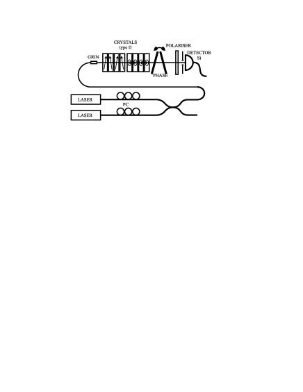
Note that the probability for upconvertion is important during a time interval given by the coherence time of the pump photons (position uncertainty). This means that the signal amplitude at a given moment comes from pump fields averaged over their coherence time. According to this ”response time” of the non-linear interaction, the outcome of our DOP-meter is the ”instantaneous” DOP as defined in the introduction.
A preliminary investigation using only two, orthogonally orientated crystals DOPJMO2 showed that an undesired phase-matching condition co-exists for photons with little wavelength difference. For example, in the same crystal, the two nonlinear interactions and are possible. This poses a serious limitation to the scheme. The wavelength separation under which this detrimental phenomenon appears is determined by the phasematching acceptance of the crystal. Hence, the narrower the wavelength acceptance of the nonlinear crystals, the better, contrary to the typical use of such crystals. To reduce the wavelength acceptance, we can use longer crystals or choose materials having better characteristics. Promising candidates as GaSe, HgS (Cinnabar) , or Banana are however hard to fabricate or difficult to manipulate. We therefore decided to stay with KTP, but to increase the crystal length. This leads to a spatial walk-off problem, limiting the effective length for SFG to well below the physical crystal length. Usually this is dealt with by adding linear birefringent crystals for compensation. Here, we compensate the walk-off using a second nonlinear birefringent crystal. As is described in Zondy , two identical nonlinear crystals are combined so that their walk-off angles are opposite and the waves generated in both are in phase. To realize the desired effective length, we use stages consisting of 4 KTP crystals each, hence our set-up contained eventually 8 nonlinear crystals in series. This is an interesting result in itself, since recently many experiments presented configurations using just pairs of nonlinear crystals photonpairs .
A structure of four 3mm KTP elements gives an effective length of almost 12mm, thereby reducing the wavelength acceptance by 4 compared to a 3mm crystal as used in DOPJMO2 . The expected wavelength phasematching acceptance becomes 4.5nm, making it possible to realize a projection onto the singlet state for wavelengths separated by 1.5nm only. Notice that the spatial walk-off is totally compensated for, so contrary to normal crystals, the spatial modes of and are as well overlapped before the second stage as before the first one. This favorizes both identical conversion efficiencies in both stages and a better spatial overlap of the created waves.
III III Results
In this section we demonstrate the performance of our projection on the singlet state with the 8 KTP crystals. To test the set-up, we use a source composed of two lasers, one at the wavelength and the other at (figure 1). Mimicking PMD, the polarization of each wavelength is adjusted separately with polarization controllers. The DOP of such a source is given by where is the angle between the states of polarization of and (Poincare sphere). With this source, it is very simple to study the response of our system for many configurations. In the following, we concentrate on the case and . Similar results were obtained for larger wavelength separations.
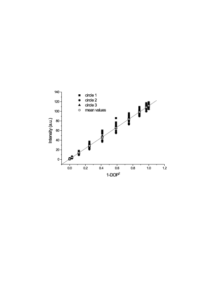
First, we characterize the quality of our projection onto the singlet state. For any input polarization combination, the output of our device has to be proportional to (Eq. 3). To well cover the possible inputs with a reasonable number of measurements, we choose polarization states on three orthogonal great circles of the Poincare sphere. For each great circle, is set to 5 polarization states separated by . For each of those states, is chosen on the same circle so that , corresponding to ten different values for the DOP. The measured data are shown in figure 2, where the values obtained from the different circles are represented by different symbols (squares, circles, and triangles). Due to the choice of polarization states, for each circle we have 5 points for a given DOP (corresponding to the 5 different absolute input polarization directions). As expected, the detected intensity reflects the DOP of our source, and is quasi-independent of the absolute polarization states of and . The residual fluctuations observed for a given DOP value are due to misalignments of the set-up. Specifically, the small variations for a DOP of 1 are essentially due to a slightly reduced visibility of the interferences between the two waves from the two stages (see DOPJMO2 for more details). We can estimate a visibility of more than 96. This is achieved thanks to a proper spatial overlap of the modes created in the two stages due to walk-off compensation in the crystals. If we estimate the precision of our measurement with the standard deviation of the fluctuations, the error of our device on the determination of the DOP is a few percent for a DOP close to 1 and about 15 for a totally depolarized source. Figure 2 also shows the mean values for a given DOP (open circles). They follow very well the linear-law predicted by the theory (solid line).
So far the analyzed signal was constant in time. In order to demonstrate that we really measure the ”instantaneous” DOP, a source with constant DOP but rapidly fluctuating state of polarization is required. We realize this by shaking the fiber linking the source to the DOP meter (fiber after the coupler in figure 1). This leads to variations in the birefringence axis direction and Berry’s phase in this fiber, and consequently the polarization states and will strongly fluctuate in time. If the amount of birefringence is small enough compared to the wavelength difference , the relative polarization angle between and (i.e. the DOP) is conserved even when agitating the fiber. In our experiment, we are manually moving the fiber leading to a time scale of the polarization fluctuations of 100ms. Accordingly, an integration time of a few seconds is chosen in order to be sure that the polarization state strongly fluctuates during this time interval. Figure 3 shows corresponding results for 3 different values of the DOP (open symbols, integration time 10s). The fiber was not shaken for the first and last measurement points to have 2 reference values. As can be seen, the same values for the DOP are obtained when shaking the fiber. This clearly demonstrates the projection onto the singlet state does indeed give the ”instantaneous” DOP.
To illustrate that this is not the case for the standard measurement techniques, we repeated the measurement using a polarimeter with 10s integration time (PAT-9000, Profile). On the first and last point, we measure the same value as with the singlet state projection. But when the fiber is shaken the measured value of the DOP strongly decreases and also fluctuates somewhat. This behavior is observed both for 10s (figure 3) and 1s integration times. Clearly, the DOP is no longer measured correctly. Note that although a polarimeter can integrate much faster than 1 second (e.g. 33ms for the PAT-9000), the same problem will be observed for fluctuations of the order of milliseconds as they can occur for PMD.

IV conclusions
A concrete application of a coherent quantum measurement has been realized: a DOP-meter. It is based on the projection onto the singlet state, and allows to measure the instantaneous DOP in a direct way. This is different from the standard, indirect method of DOP evaluation (polarimetric technique) where the DOP is averaged over the integration time of the detection, which is typically longer than the coherence time of the signal to be measured. Consequently, for a signal with temporally fluctuating polarization only the first method gives the correct DOP.
Experimentally the projection onto the singlet state is realized exploiting up-convertion in two type II nonlinear crystals. In order to increase the efficiency of the process and to be able to measure signals with narrow spectra, the effective crystal length should be large. We achieved this by stacking 2x4 KTP crystals of 3mm length in a walk-off compensation arrangement, giving an effective length of almost 12mm for each of the two stages. With this compensation technique, we obtained a high quality DOP measurement for wavelengths separated by 2nm. Further, we demonstrated that the projection onto the singlet state gives indeed the ”instantaneous” DOP. For a signal with temporally fluctuating polarization we still obtained the correct value, whereas this was not the case for a standard polarimetric measurement.
Acknowledgements: Financial support from the Swiss OFES in the frame of the COST 265 project, EXFO Inc (Vanier, Canada), and the Swiss NCCR ”Quantum photonics” are acknowledged.
∗Matthieu.legre@physics.unige.ch
References
- (1) M. Born, and E. Wolf, Principles of Optics, Sixth Edition, (Pergamon Press, Oxford, 1980).
- (2) T. P. Spiller, in Proceedings of the IEEE 84, 1719, 1996.
- (3) A. Acin, R. Tarrach, and G. Vidal, Phys. Rev. A 61, 062307, 2000.
- (4) S. Massar, and S. Popescu, Phys. Rev. Lett. 74, 1259, 1995.
- (5) N. Gisin, J. of Mod. Optics 48, 1397, 2001.
- (6) C. H. Bennett et al., Phys. Rev. Lett. 70, 1895, 1993; Y.-H. Kim et al., Phys. Rev. Lett. 86, 1370, 2001.
- (7) P. G. Kwiat et al., Phys. Rev. A 60, R773, 1999; Y.-H. Kim et al., Phys. Rev. A 62, 011802, 2000.
- (8) M. Karlsson, Opt. Lett. 23, 688, 1998.
- (9) F. Roy et al., in Technical Digest OFC’99, TuS4, 275, 1999; M. Karlsson et al., in Technical Digest OFC’01, MO1, 2001.
- (10) J.-J. Zondy et al., in Proceedings of SPIE 27000, 66, 1996.
- (11) M. Legré, M. Wegmüller, and N. Gisin, J. of Mod. Optics in press.