Experimental demonstration of quantum source coding
Abstract
We report an experimental demonstration of Schumacher’s quantum noiseless coding theorem. Our experiment employs a sequence of single photons each of which represents three qubits. We initially prepare each photon in one of a set of 8 non-orthogonal codeword states corresponding to the value of a block of three binary letters. We use quantum coding to compress this quantum data into a two-qubit quantum channel and then uncompress the two-qubit channel to restore the original data with a fidelity approaching the theoretical limit.
pacs:
03.67.Hk, 03.65.Ta, 42.50.–pIntroduction
The coding of messages is a fundamental issue in information
theory. There are two basic coding problems, namely how to
represent messages as efficiently as possible and how to
transmit messages as precisely as possible. The former is called
source coding, and is related practically to data
compression, while the latter is called channel coding
and is concerned with error correction. All information processing
techniques are connected with these two kinds of coding problem.
We focus on source coding in this report.
Essentially, source coding entails the coding of common alphabet in a message as short sequences of code letters, such as the binary digits , and uncommon alphabet as longer sequences, to make the average length of the coded message as short as possible. The unequal frequencies of the letters imply a redundancy that enables the compression of the message. Shannon’s source coding theorem gives the bounds on the degree a classical message can be compressed. For a source of alphabet with given prior probabilities , the minimum average length of the coded message is given by the Shannon entropy
| (1) |
takes its maximum value when all alphabet appear with equal probability, that is, when we know nothing better than a random guess for each element. Then any compression is impossible.
In quantum domain, there is another kind of redundancy when the letters are conveyed by the non-orthogonal quantum states, , , , with corresponding probabilities , , , . Significantly, compression is possible here even if , in contrast to the classical case. Recently Schumacher and Jozsa derived the quantum version of the source coding theorem. The quantum noiseless coding theorem Schumacher95 ; Jozsa_Schumacher94 implies that by coding the quantum message in blocks of letters, qubits are necessary to encode each block in the limit , where is the von Neumann entropy of the density operator representing the average state of the letter states.
In addition to its central role in quantum information theory, the compression of non-orthogonal data sets has significant practical advantages. For example, in long-haul optical communication channels one must deal with sequences of attenuated weak coherent pulses, that is, non-orthogonal states. Expensive quantum channel resources can be saved by compressing the sequences before storing or relaying to another channel.
Given its fundamental as well as practical importance, it is
perhaps surprising that quantum source coding has not been
demonstrated experimentally to date. We report an experimental
demonstration of the reliable communication of 3-qubit codewords
over a 2-qubit quantum channel. The minimum resources needed for
an analogous classical channel would be 3 bits per codeword.
Quantum coding protocols
Our demonstration is based on the example given by Jozsa and
Schumacher Jozsa_Schumacher94 . Imagine Alice needs to send
Bob a message composed of an alphabet of 2 letters, “” and
“”, represented by the letter states and
,
| (2) |
Here , are an orthonormal (computational) basis, , , and for clarity we assume and are real numbers. Let the letter states occur with equal likelihood so that the density operator representing the average letter state is . The corresponding von Neumann entropy is .
If the letter states are orthogonal, , then 1 qubit (or classically 1 bit) is needed to encode each letter faithfully. In this case a sequence of letter states cannot be compressed to a smaller code. However, the von Neumann entropy of is 0.4690 bits for the case Jozsa_Schumacher94 . According to the quantum noiseless coding theorem, in the limit of large block sizes Alice needs approximately qubit per letter state to faithfully transmit the message to Bob.
Following Jozsa_Schumacher94 we use blocks of 3 letter states:
| (3) | |||||
where and , and . The index selects one of 8 possible letter state configurations. In our quantum coding scheme differ , Alice first applies the unitary transformation which leaves all computational bases states unchanged except for the following mapping and . The state of a block after the application of is
| (4) |
where
| (6) | |||||
Alice then makes a projection measurement of the first (leftmost) qubit in the computational basis. The last two qubits represent the coded block state sent to Bob. We consider two different protocols corresponding to two different actions Alice takes when the projective measurement results in the state . Essentially, the coding protocols amount to a perfect transmission of the most likely parts of letter state configurations, and a less faithful transmission of, or even discarding of, the remaining less likely part.
The first protocol, which we shall label P1, is to treat the projection measurement result as a failure. Under this protocol the state of the 2-qubit quantum channel is
| (7) |
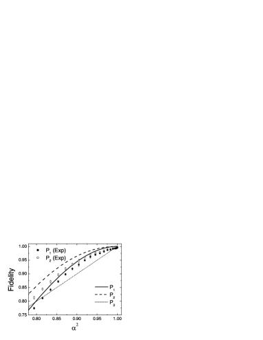
with probability and a state of zero overlap with any block state with probability . Bob decodes the state at his end of the quantum channel by preparing an extra qubit in the state and applying the inverse of ; this results in the decoded state . The fidelity of the whole quantum coding-decoding operation for P1 is given by
| (8) |
is plotted as the solid curve in Fig. 1 and has a value of at .
The second protocol, P2, yields a higher fidelity than that of P1. In this case Alice prepares the quantum channel in the state in the event that her projection measurement results in the state . This operation results in the average state of the quantum channel as
| (9) |
Bob again adds an extra qubit in the state and applies the inverse operation to produce state which has a corresponding fidelity of
| (10) |
The value of is plotted as the dashed curve in Fig. 1. has a value of at .
Finally, Jozsa and Schumacher also considered the simple protocol, P3, where Alice discards the state of every third letter and encodes the remaining letters in a block of 2 qubits, and Bob generates the state for the missing letter state. This protocol yields an average fidelity of
| (11) |
which is plotted as the dotted curve in Fig. 1.
Optical scheme
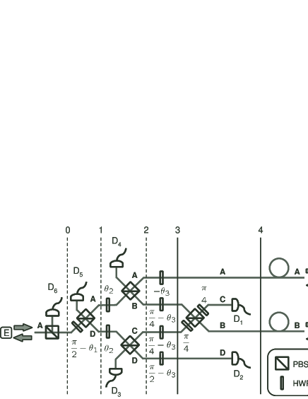
Fig. 2 shows an ideal single-photon linear
optics implementation of the block coding scheme of the previous
section using polarizing beam splitters, wave plates
and photodetectors. One photon is used to represent the 3 qubits
in terms of two location qubits (the first 2 qubits) and a
polarization qubit LinearOptGating (the third qubit).
The paths labeled A, B, C and D represent the states ,
, and of the first two qubits,
respectively, and the polarization directions in the plane and
perpendicular to the plane of the optical circuit represent the
states and of the last qubit, respectively. We
parameterize the th letter state by the angle
. The orientation of the
fast axis of each wave plate to the vertical direction is given
beside the wave plate in the figure.
First we discuss the preparation of the 3-qubit block state . A horizontally-polarized photon enters the quantum circuit at position E. The first location qubit is prepared by the wave plate and the polarization beam splitter between vertical lines labeled 0 and 1 in terms of angle . Similarly, the second location qubit and the polarization qubit are prepared between the vertical lines labeled 1 and 2, and 2 and 3, respectively. (Note that the photodetectors D3, D4, D5 and D6 are not used in state preparation.) The fully state-prepared block appears as a photon in a superposition of 4 path and two linear polarization modes along the vertical line labeled 3. This is the 3-qubit message Alice wants to compress and communicate to Bob.
Next we discuss the quantum coding which takes place between vertical lines 3 and 4. The unitary transformation is performed by the polarization beam splitter and the two wave plates in this section. The projection measurement of the first qubit is performed by the photodetectors D1 and D2 where the detection or non detection of a photon projects the state onto or , respectively. The circuit in Fig. 2 implements protocol P1 explicitly: if the photodetectors D1 and D2 detect a photon no quanta will be present in the quantum channel and so the coding results in failure. The projective measurement is destructive in this case. Protocol P2 can be implemented by switching a horizontally-polarized single photon source into the optical path A to encode the state each time one of the photodetectors D1 or D2 detects a photon. The encoded (compressed) 2-qubit message appears along vertical line 4. This is transmitted to Bob.
The decoding of the quantum channel AB at Bob’s site requires a
mirror image of the quantum circuit in Fig. 2
between lines 3 and 4 but without the photodetectors D1 and
D2. Moreover, the mirror image of the circuit to the left of
the line 3 can be used to determine the fidelity of the decoded
block message. The fidelity test results in a ‘yes’-‘no’ answer
for each coded-decoded block state as follows. The ‘yes’ answer
(i.e. perfectly reconstructed letter block) is indicated by the
horizontally-polarized photon emerging from the mirror image of
point E. A ‘no’ answer is indicated by the photon being detected
by one of the photodetectors D3, D4, D5 or D6 in the
mirror
image circuit 7outcomes .
Experimental Implementation
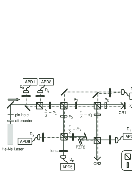
Our actual experimental circuit is shown in
Fig. 3. Again, the orientation angle
of each wave plate is given in the figure. For
practical convenience, we did not construct an additional
mirror-image circuit for the decoding and fidelity check. Instead
we use corner reflectors (CR1 and CR2) to reflect the light in the
quantum channel back through the circuit (shown as dotted lines in
the figure) so that the coding and state-preparation circuits
operate as decoding and state-measurement circuits for the
reflected light. We use strongly attenuated light from a He-Ne
laser (wavelength 632.8 nm) as our single photon source. The CW
laser output of 1 mW power is attenuated to 50 fW which
corresponds to an average photon flux of 105 photons/sec. The
average time between photons through our experiment far exceeds
the time taken for light to pass through the circuit
( s).
We use multimode optical fibers with coupling efficiency of more than 80% to direct the photons exiting the circuit to silicon avalanche photodiodes (APDs). The quantum efficiency and dark count of the APDs are typically 70% and less than 100 counts/sec, respectively. The labels for each APD (D1–D6) correspond to those of photodetectors in Fig. 2 and the APD labeled D0 detects the ‘yes’ answer of the fidelity test. Since we do not need to discriminate the photodetection between D4 and D5, we use one APD for these detectors.
In essence, the optical circuit consists of a Michaelson and a Mach-Zehnder interferometers controlled by Piezo transducers PZT1 and PZT2, respectively. We use a bright reference light and adjust the voltages of PZT1 and PZT2 to produce visibilities of more than 98% for these interferometers. The reference light is then switched off and the signal photons are guided into the circuit. The single photon events are counted by six APDs for each block state . The gating time of the APDs is 5 sec with the combined count over 1 sec being of the order of 105. Since the whole apparatus is shielded by a black box, the number of background photons is much smaller than the dark count of the APDs. Also we estimate the number of events where two photons are present simultaneously in the circuit to be less than half the dark count.
Our use of a photon source with random arrival times means that the quantum coding-decoding operations occur in the context of post-selection measurements; that is, we know that a quantum coding-decoding operation has taken place after it has occurred, and, due to the limited efficiency of the photodetectors, in a subset of possible cases.
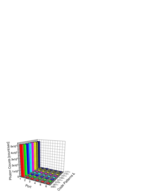
The experimental fidelity for protocol P1 is given by
| (12) |
where is the number of photons detected by the detector Dj for the block state . As an example, Fig. 4 shows the photon counting data for the letter state with for which the fidelity . By varying the angle the fidelity of our quantum coding-decoding experiment can be compared by the theoretical predictions given of the previous section over a range of values. The results are shown in Fig. 1 as solid circles.
For protocol P2, rather than switching a horizontally-polarized light source into channel A each time one of the photodetectors D1 or D2 records a photon, we perform a 2 step procedure as follows. The first step is the same as for protocol P1 and, in fact, we use the same photon counting data as described. The second step corresponds to the transmission of a horizontally-polarized photon in channel A for each of the photons detected by D1 and D2 in the first step. For this purpose, the corner reflector CR1 is removed and horizontally-polarized and attenuated light from a He-Ne laser is directed into the circuit. The number of photons used (i.e. the total number of photons detected by all APDs) in this second step is adjusted to be for each corresponding block state . We can do this adjustment with an accuracy of % by carefully controlling the gating time of the APDs. The total fidelity for this protocol is calculated as follows:
| (13) |
where is the total number of photons
detected by D0 in the second step. We obtain the fidelities
corresponding to several values and plot them as open
circles in Fig. 1. The experimental fidelities
for both protocols exceed that of the simple protocol.
Discussion
A message of equal-likely letters is not compressible classically.
In contrast, quantum source coding allows a quantum message of
equally likely (but non orthogonal) letter states to be compressed
Schumacher95 ; Jozsa_Schumacher94 . Our compression of
3-qubit codewords gives a clear demonstration of this fundamental
principle.
The practical application of quantum source coding faces several challenges. An immediate task is to demonstrate quantum source coding using a single-photon-on-demand source. Another is to replace spatial mode qubits with frequency mode qubits as this leads to compression of bandwidth of quantum carrier. Of direct practical importance is to demonstrate the coding and decoding of a source of weak coherent states. Quantum circuits based on measurement induced non-linearities and non-classical light sources have potential in this regard. Our experiment is the first step towards realizing these practical goals.
Acknowledgements.
This work was supported by the British Council, the Royal Society of Edinburgh, the Scottish Executive Education and Lifelong Learning Department and the EU Marie Curie Fellowship program.References
- (1) B. Schumacher, Phys. Rev. A51, 2738 (1995).
- (2) R. Jozsa and B. Schumacher, J. Mod. Opts. 41, 2343 (1994).
- (3) We perform the unitary transformation before the projection operation, otherwise our scheme is identical to that of Jozsa_Schumacher94 .
- (4) N. J. Cerf, C. Adami, and P. G. Kwiat, Phys. Rev. A 57, R1477 (1998); R. J. C. Spreeuw, Found. Phys. 28, 361 (1998); S. Takeuchi, Proc. p.299, PhysComp96 (Boston, 1996).
- (5) We note that the photons arriving at D6 have only vertical polarization whereas those arriving at D3 to D5 can have either vertical or horizontal polarization giving, in principle, 7 distinguishable outcomes for a ‘no’ answer.