Input states for quantum gates
Abstract
We examine three possible implementations of non-deterministic linear optical cnot gates with a view to an in-principle demonstration in the near future. To this end we consider demonstrating the gates using currently available sources such as spontaneous parametric down conversion and coherent states, and current detectors only able to distinguish between zero or many photons. The demonstration is possible in the co-incidence basis and the errors introduced by the non-optimal input states and detectors are analysed.
pacs:
03.67.Lx,42.50.-pI Introduction
Optics is a natural candidate for implementing a variety of quantum information protocols. Photons make beguiling qubits: at optical frequencies the qubits are largely decoupled from the environment and so experience little decoherence, and single qubit gates are easily realised via passive optical elements. Some protocols, notably quantum computation, also require two-qubit gates. Until recently this was regarded as optically infeasible, since the required nonlinear interaction is much greater than that available with extant materials. However, it is now widely recognised that the necessary nonlinearity can be realised non-deterministically via measurement, and that deterministic gates can be achieved by combining such non-deterministic gates and teleportation 01klm46 .
There are a number of proposals for implementing a non-deterministic cnot gate with linear optics and photodetectors 01klm46 ; 02ralph012314 ; 0111092 ; ndCNOT2 ; ndCNOT3 ; 0107091 . The proposals require deterministic, or heralded, single photon sources, and/or selective detectors, that can distinguish with very high efficiency between zero, one and multiple photons. Current commercial optical sources and detectors fall well short of these capabilities. Although there are a number of active research programs aimed at producing both efficient selective detectors 02imamoglu163602 ; 02james183601 , and deterministic photon sources qDOT1 ; qDOT2 ; diamond , nonselective avalanche photodiodes, spontaneous parametric downconversion (SPDC) and coherent states remain the best accessible laboratory options. While we could side-step the single photon source problem by using an SPDC source conditioned on the detection of a photon in one arm if we had selective detectors, demonstrating a four-photon cnot gate without quantum memory would be frustratingly slow.
In this paper we examine three proposals which allow a cnot to be implemented non-destructively on the control and target modes, to ascertain under what conditions it is possible to demonstrate and characterise the gates operation using SPDC sources, coherent states and non-selective detectors (detectors only able to resolve zero and multiple photons). The aim is to identify a scheme that allows a scalable cnot implementation to be initially examined with current sources and detectors, and into which we can easily incorporate single photon sources and selective detectors as they become available.
Typically the gates involve four photons with the qubit states are encoded in the polarisation state of the control and target modes and , and the cnot operation is implemented with the aid of some ancillary modes , etc. We will consider starting with the control and target modes each in a general superposition (we could also consider initially entangled states though these may be more difficult experimentally)
| (1) |
with , and where and are bosonic creation operators for mode and etc. In the interest of brevity we will use the notation above where we write the state in terms of creation operators acting on the vacuum state.
The modes are first entangled with a linear optics network comprised of beamsplitters , phase shifters, waveplates, and polarising beam splitters. Finally the gate is conditioned on detecting the ancillary modes in some appropriate state, which leaves the state of the control and target modes as if a cnot had been applied.
The key simplification for our purposes is to detect in the ‘coincidence basis’ — where we detect the output of the ancillary modes and also of the target and control modes and postselect out those events that do not simultaneously register a photon in all four modes. The advantage of this configuration is that now we can use non-selective detectors, since if we get a “click” on all four detectors we’ve accounted for all the photons in the system. This is a much less stringent requirement on the detectors and in particular can be fulfilled by existing avalanche photodiodes. We model the non-selective detectors with a positive-operator-valued measure (POVM), with the POVM elements associated with detecting no photons or photons (one or more) simply being and respectively.
The output state of a type-I SPDC can be described as
| (2) | |||||
| (5) |
where and the sum is over even where is the number of photons in each term.
Now suppose that our input state to the optical circuit is some initial pure state , and that after passing through the linear optical elements we are left in the state . The probability that we get a count simultaneously in modes , , and with non-selective detectors is
| (6) |
For the ideal case where we had single photon inputs to the gate, we will label this probability as . We can now introduce the “single photon visibility” as a figure of merit for how close the gate operates to the ideal:
| (7) |
where is the product of the probability of obtaining the single photon terms from the source, with the probability of the gate functioning. The “error” where is the actual probability of obtaining a count on the detectors. The maximisation is over all qubit input states to the gate. Hence if the error totally dominates the visibility is close to zero, if the noise is small the visibility is close to one. As a guide a visibility of corresponds to an error a quarter of the size of the single photon “signal” .
II Simplified KLM CNOT
In the originally proposed non-deterministic cnot gate 01klm46 the nonlinear sign shift elements were interferometric: these elements can be replaced by sequential beamsplitters to make a simplified cnot gate 02ralph012314 , one example of which is
| (8) | |||||
where represents a beam splitter with the following action
| (9) | |||||
| (10) |
and is the reflectivity. The angle choices for the gate are given by and ; and are the control and target modes and , , and are independent ancillary modes. The gate is conditioned on detecting a single photon in the modes and and detecting no photons in the modes and .
Consider the case where both the control, target and ancillary photons are supplied by two independent SPDC sources. The input state is which can be written as a sum over total photon number
| (13) | |||||
The control and target horizontal and vertical polarisation modes are then each mixed on a beamsplitter so that we achieve the input state (1) for those modes.
Since we are postselecting on getting a ‘click’ at four detectors then the terms with will always get postselected out. Similarly, the terms with will get postselected out if we used selective detectors otherwise they represent error terms. In the latter case, so long as these terms will be small. For the case were , three input terms contribute:
| (14) |
While the first of these terms is equivalent to having four initial Fock states, the remaining two terms have the possibility of surviving the postselection criteria and skewing the statistics observed. Fortunately these last two terms lead to output terms which all get postselected out in the coincidence basis (e.g. two photons in the control mode). This means that with selective detectors we could in principle postselect out all terms that do not correspond to single photon inputs from the output statistics. With non-selective detectors the error terms will scale at least as in amplitude (due to the terms) so the figure of merit will scale with (taking ) as and is typically very small.
Now consider the situation where a SPDC supplies the two photons for the control and target modes and weak coherent states are used for the ancillary modes. The input state is then where and will be the creation operators for the coherent states. After rearranging the state as a primary sum over photon number we get
| (15) |
Again, terms with will get postselected out and terms with will be weak error terms. The extra freedom from two independent coherent states means that now there will be nine terms with and only one of these is equivalent to using single photon inputs.
The terms were a single coherent state supplies all the photons always gets postselected out. By setting the two terms where a single coherent state supplies two photons and the paramp supplies two will cancel each other due to the symmetry in the circuit. Finally the term where the paramp supplies all the photons is postselected out as before. This means that we will still get errors arising from the input terms:
| (16) |
Note that these do not depend on the input state that is encoded on the control and target modes and by setting we can scale away these terms relative the single photon terms. Unfortunately this means that we cannot beat the photon collection rate that could be achieved using two independent SPDC sources.
It should be noted that all the observations made for the simplified KLM cnot also hold for the full KLM cnot in the coincidence basis. However from the perspective of an initial demonstration of the gate the simplified version is more desirable. In the following two sections we will compare these results against two other implementations of optical cnot gates.
III Entangled ancilla CNOT
In a recent paper, Pittman, Jacobs and Franson 0107091 proposed using entangled ancilla to further simplify implementation of the cnot. Consider that we have at our disposal an entangled state , then we can implemented the cnot between modes and by first applying the unitary
| (17) |
where represents a half-wave plate on mode and is a polarising beam splitter in modes and with the effect that , , , and . Finally the resulting state is then conditioned on detecting a single photon in modes and . The raw success probability of this gate is which rises to if fast feed-forward and correction is used.
Consider that the entangled pair in modes and are provided by two type-I parametric downconverting crystals sandwiched together. We’ll fix the relative phase to get a particular Bell pair for the two photon term:
| (18) | |||||
where the modes are , , , and respectively. Such sources have been previously built and provide a relatively bright source of polarisation entangled photons 99kwwae773 ; 99wjek3103 . We can write this source succinctly as
| (21) | |||||
| (22) |
With another independent paramp, , supplying the photons for the control and target modes, the input state becomes
| (23) |
where we will encode the qubits in the polarisation state of the control and target modes, as in (1).
Again all terms with will get postselected out. There are six terms with of which two terms represents our single photon input terms, the rest are error terms due to the sources. With non-selective detectors terms with will also contribute to the error.
The four photon terms in the output state that do not get postselected out are
| (24) | |||||
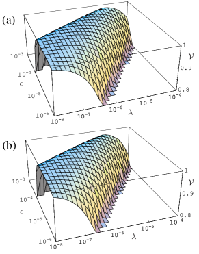
and by making we can recover the single photon terms and the action of the cnot with selective detectors. This of course means that the count rate with this gate would be considerably less than with the simplified KLM gate. With non-selective detectors, if we make too small the error due to the six photon input terms will dominate, so there is an optimum for a given see figure 1 (a).
There does not appear to be a way of using two coherent states to replace one of the SPDC sources. If we replace either the control or target mode then it is hard to see how the and terms could cancel as with the simplified KLM cnot since these terms will have factors that depend on the encoded qubit. Similarly replacing the source of entangled photons would then mean we would have to entangle the single photon components which is difficult.
IV Knill CNOT
A recent numerical search for optical gates by Knill yielded a cnot gate 0110144 which operates with a probability of and is described by the following unitary,
| (25) | |||||
where is a phaseshift of on mode and the reflectivities are given by , and . The gate requires two ancillary modes and initially in Fock states to be finally detected also in single Fock states.
Consider the case where both the control, target and ancillary photons are supplied by two independent SPDC sources. The input state is given by (13) with the usual qubit encoding as in equation (1). We will again get the three terms (14) possibly contributing to the error for . The last term again leads to output terms which all get postselected out in the coincidence basis. Unfortunately the output terms produced by the second term do not get postselected out leading to inherent errors in the statistics we will observe. Notice however that all these terms will be proportional to so again by making we can scale these terms away with selective detectors at the expense of the count rate. With non-selective detectors there will again be an optimum , see figure 1 (b), which is very similar to the previous gate.
V Conclusion
We have examined three possible implementations for linear optics cnot gates with a view to experimentally demonstrating their operation in the near future. In considering demonstrating the gates with SPDC and coherent state sources and non-selective detectors there is a clear advantage to the simplified KLM cnot gate, where the inherent symmetries in the gate allow the use of two independent SPDC sources to supply the control, target and ancillary photons, with errors from the use of non-Fock states making little contribution. The other two implementations suffer from errors introduced by the non-Fock state inputs which cannot be postselected out. While the situation may be mitigated somewhat by using a weak SPDC source this would occur at the expense of the count rate of valid events that may be collected from the gate.
The conclusion we arrive at is that an experimental program focusing on the simplified KLM cnot gate would then allow immediate characterisation of the gate with current sources and detectors, with the operation of the gate in a non-destructive fashion becoming possible when single photon sources and selective detectors become available.
We would like to acknowledge support from the the Australian Research Council and the US Army Research Office. AG was supported by the New Zealand Foundation for Research, Science and Technology under grant UQSL0001. WJM acknowledges support for the EU project RAMBOQ. We would also like to thank Michael Nielsen, Jennifer Dodd, Nathan Langford, Tim Ralph and Gerard Milburn for helpful discussions.
References
- (1) E. Knill, R. Laflamme, and G. Milburn, Nature 409, 46 (2001).
- (2) T. C. Ralph, A. G. White, W. J. Munro, and G. J. Milburn, Phys. Rev. A 65, 012314 (2002).
- (3) H. F. Hofmann and S. Takeuchi, Phys. Rev. A 66, 024308 (2002).
- (4) T. C. Ralph, N. K. Langford, T. B. Bell, and A. G. White, Phys. Rev. A 65, 062324 (2002).
- (5) K. Sanaka, K. Kawahara, and T. Kuga, quant-ph/0108001, 2001.
- (6) T. Pittman, B. C. Jacobs, and J. D. Franson, Phys. Rev. A 64, 062311 (2001).
- (7) A. Imamog̈lu, Phys. Rev. Lett. 89, 163602 (2002).
- (8) D. F. James and P. G. Kwiat, Phys. Rev. Lett. 89, 183601 (2002).
- (9) P. Michler et al., Science 290, 2282 (2000).
- (10) M. Pelton et al., quant-ph/0208054, 2002.
- (11) A. Beveratos et al., Eur. Phys. D 18, 191 (2002).
- (12) P. G. Kwiat et al., Phys. Rev. A 60, R773 (1999).
- (13) A. G. White, D. F. V. James, P. H. Eberhard, and P. G. Kwiat, Phys. Rev. Lett. 83, 3103 (1999).
- (14) E. Knill, quant-ph/0110144, 2001.