Quantum computing with spatially delocalized qubits
Abstract
We analyze the operation of quantum gates for neutral atoms with qubits that are delocalized in space, i.e., the computational basis states are defined by the presence of a neutral atom in the ground state of one out of two trapping potentials. The implementation of single qubit gates as well as a controlled phase gate between two qubits is discussed and explicit calculations are presented for rubidium atoms in optical microtraps. Furthermore, we show how multi-qubit highly entangled states can be created in this scheme.
PACS numbers: 03.67.-a, 32.80.Pj, 42.50.-p
Optical lattices olat and arrays of optical microtraps PRLBirkl are promising candidates for the implementation of quantum information processing with neutral atoms. Many of the requirements for quantum computation with optical microtraps have been recently demonstrated in 2D arrays of traps with atoms per trap PRLBirkl . Some remarkable characteristics of optical microtraps are the possibility to scale, miniaturize and parallelize the required atom optics devices. In addition, they offer two fundamental advantages over optical lattices: (i) the possibility of individually addressing single traps due to the large separation of the microlenses foci, e.g., ; and (ii) the independent displacement of rows and columns of microtraps and, eventually, of single microtraps. Single atoms in dipole traps singledt and the Mott insulator transition with one atom per trap in optical lattices singleMott have been reported, and, therefore, the achievement of 1D and 2D arrays of optical microtraps containing none or one atom per trap in a deterministic way can be foreseen for the near future. We will make use of all these features of optical microtraps to propose a novel implementation for quantum information processing.
In our scheme, each qubit consists of two traps separated by a distance and one single atom. Per definition, the detection of the atom in the ground state of the left trap represents and in the right trap , i.e., and , where are the vibrational ground states of the left and right trap, respectively. Throughout the paper we will call this implementation the spatially delocalized qubit (SDQ), since with the position operator. To implement the SDQ we will assume that we are able to deterministically store none or one single atom per trap and cool it to the vibrational ground state in 3D.
Single and two-qubit gate operations will be performed by adiabatically approaching two traps which will be modeled as follows: The initial separation of the traps is . The process of approaching them to the minimum separation takes a raising time . The temporal evolution of the distance is described by the first half of a period of a cosine. The two wells remain at the minimum separation for an interaction time and, finally, are adiabatically separated to the initial distance. To simplify the numerical analysis we will assume piecewise harmonic trapping potentials as in ref. ourQCpaper and, eventually, consider realistic Gaussian potentials as they are present in the experiment PRLBirkl ; BirklOC .
Single-qubit operations, e.g., a Hadamard gate, are performed by adiabatically approaching the traps and allowing tunneling to take place. In order to illustrate this operation, it is convenient to consider the two lowest energy eigenstates of the double well potential. These two states are symmetric and antisymmetric, denoted by and respectively, with energies and being the splitting frequency. In terms of these states, our qubit basis reads: , and . Let us assume that the atom is initially in the left trap, i.e, , then it is straightforward to check that its time evolution will be given by
| (1) |
Thus, the atomic wavefunction oscillates in a Rabi-type fashion between left and right traps at the flopping frequency . Obviously, for large trap separations states and become degenerate in energy, i.e., for , and then the atom does not evolve in time (up to a trivial phase). Therefore, it is possible to realize single-qubit operations via tunneling by experimentally controlling the “Rabi frequency” through , and .
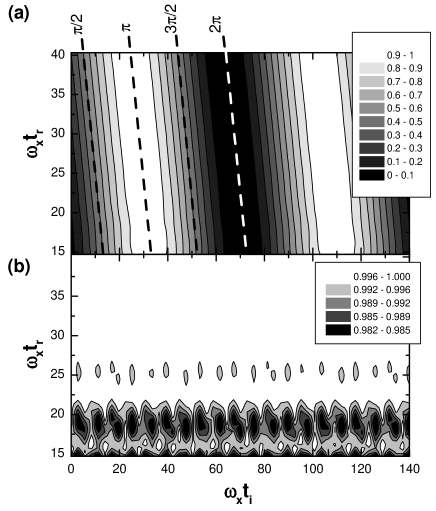
These single-qubit operations are illustrated in Fig. 1 through a numerical integration of the 1D Schrödinger equation in the parameter plane versus with being the initial state. Fig. 1 shows (a) the population of state , denoted by , and (b) the total ground state population of left and right traps, i.e., , after the whole cycle of approaching and separating the traps. This oscillating population resembles the Rabi-flopping in the interaction of a laser with a two-level system and, for this reason, we have added in Fig. 1 dashed lines indicating the laser pulse notation conventionally used in quantum optics. For small , non-adiabaticity results in the population of excited vibrational states, which, as shown in Fig. 1 (b), yields . In what follows, we will focus only in the adiabatic regime.
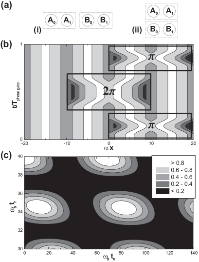
For the two-qubit gate operations we assume that the two qubits are arranged either (i) in a 1D configuration, i.e., the four traps form a line, or (ii) side-by-side in a 2D configuration, i.e., the traps form a square, c.f. Fig. 2(a). The traps involved are labeled , for the first qubit and , for the second, and the respective ground states are denoted , and , . A two-qubit gate will be realized via the collisional interaction between bosonic neutral atoms na2 . We will consider 87Rb atoms whose collisional interaction can be described by a contact potential of the form , where is the -wave scattering length in the spin triplet. Because the states and are localized in different positions, it is enough to perform a suitable spatiotemporal variation of the potentials in order to pick up a collisional phase shift e.g. only if both atoms are in . This is sufficient to implement a two-qubit phase gate, which transforms product states , , into and, supplemented by arbitrary single-qubit gates, forms a universal set of gates.
For the in-line arrangement, the change of the potential leading to a phase gate is shown in Fig. 2(b), where horizontal and vertical axes denote space and time, respectively. As the first step a pulse is applied on the second qubit, exchanging and . During this step only single-particle phases arise which can be included into the definition of the single-particle states. If the initial state was then after the pulse, traps and would contain no atom. For initial states or , an atom would be either in or in and as seen before, we could approach and eventually separate and such that a pulse is applied with integer. In this case initial and final state coincide, except for a single particle phase which again can be included into the definition of or . If we started from , then after the first pulse and would both be occupied, and during the pulse the two atoms would collide. For an adiabatic evolution we can neglect not only the probability to populate excited vibrational states, but also to find two atoms in the same trap, since, due to the collisional interaction, these states are not degenerated with states where each atom occupies a different trap ourQCpaper . Thus for initial and final state are the same except for a phase and, in order to realize the desired phase gate operation, we need its collisional part to be an odd multiple of . The fidelity of this operation can be expressed as , which is plotted for the adiabatic regime in Fig. 2(c). Here is the final probability to find the atom in the same state as it was before the pulse, neglecting the collisional phase. To calculate the collisional phase , we have integrated the two-particle 1D Schrödinger equation replacing by an effective 1D interaction potential under the assumption that no transverse excitations occur na2 . Finally, to complete the phase gate operation another pulse is applied to the second qubit.
In the case of 2D arrays of traps, as they are typically realized in the experiment PRLBirkl , the easiest operation is to move complete columns of microtraps. To realize the gate it is enough to be able to move selectively some columns, with the additional benefit that the operation is applied to many pairs of qubits in parallel which might allow for an easy implementation of error correcting codes. For the side-by-side arrangement, the initial and final pulse can be omitted and only the pulse between traps and is needed. Although conceptually much more easier, the implementation in this arrangement demands the ability to move single traps instead of columns which makes it experimentally more involved.
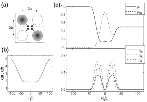
The SDQ scheme allows also for the creation of maximally entangled states in a very straightforward way. Let us consider again four microtraps in the side-by-side arrangement, Fig. 3(a), with the two atoms located in the upper-left and lower-right traps, respectively, i.e., the initial two particle state is . During an approach of the traps, Fig. 3(b), the general two-particle state of the system will be:
| (2) | |||||
Thus, the state of the system includes the four states of the computational basis, but also double qubit occupation, defined as =, and double trap occupation, = . In order to create maximally entangled states, the approach of the traps must be both, adiabatic and symmetric, i.e, . Again, adiabaticity means that the population of excited vibrational states, as well as of double trap occupation states, can be neglected, c.f. Fig 3(c). A symmetric approach results in during the whole process. In particular, these populations oscillate at the same frequency and, at the oscillation nodes, the state of the system is a combination only of and . Therefore, choosing appropriate parameter values, such as those of Fig. 3, it is possible to obtain a maximally entangled state at the end of the process. Clearly, it is straightforward to generalize this approach to more than two qubits and, consequently, to prepare multiparticle entangled states in one single step.
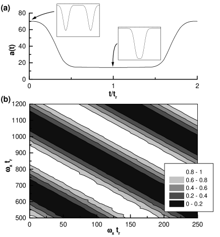
Although we have assumed harmonic trapping potentials so far, the experimental situation is described by Gaussian potentials of the form . An analysis of the energy eigenvalues and eigenstates of the superposition of two such potentials as a function of the trap separation shows that the cosine function previously used to adiabatically approach the traps leads to values of larger by more than two orders of magnitude compared to harmonic traps. We have therefore applied the techniques from optimization to optimize the temporal variation of the trap separation while suppressing the population of excited vibrational states. For , Fig. 4(a) shows the result of this optimization for single-qubit operations, where the optimization is done with respect to the symmetric ground and first excited states. We notice that for the minimal distance the two traps are no longer separated by a tunneling barrier, but they form a single flat trap. Fig. 4(b) shows the population of the right trap, . The error rate due to the excitation of other vibrational states can be made smaller than for which is a reduction by one order of magnitude compared to the non-optimized function .
Typical trapping frequencies for state-of-the-art 2D optical microtraps arrays of 87Rb atoms are - s-1 in the transverse directions and - s-1 along the laser beam direction PRLBirkl ; BirklOC . In order not to populate excited vibrational states and neglect double trap occupation, the trap displacement has to be adiabatic with respect to the lowest relevant trapping frequency. This adiabaticity condition yields realization times for single and two-qubit operations on the order of ms and ms, respectively. These values should be compared with the typical lifetime of the atoms in the microtraps of s, and the rate of spontaneous scattering of photons from the trapping laser of - s-1. The rate of decoherence for qubits encoded in external states is further reduced by a factor of 10-100 due the strong localization and almost harmonic trapping potential echo . In addition, sideband cooling can be used to cool the atoms to the ground state of each trap in all dimensions.
As discussed here, the SDQ configuration with neutral atoms in optical microtraps presents important practical advantages with respect to the use of either internal states na2 ; na or vibrational states vibrational ; ourQCpaper to encode the qubit. (i) Spontaneous emission leads to decoherence only in a much reduced fashion. As long as the microtraps are moved adiabatically, atoms remain in the ground state of both the internal and external degrees of freedom for typical gate times. (ii) There is no momentum transfer in single or two-qubit operations as, in general, it is the case when these operations are realized via laser pulses. This momentum transfer could heat the atoms and, eventually, take them out from the microtrap. (iii) There is no need of state dependent interaction to realize the two-qubit operations. In the SDQ configuration one has that and, therefore, we can make use of the fact that all interactions are space dependent to realize the gate. (iv) The measurement of the state of the system is straightforward. Optical microtraps can be separated to distances well beyond which allows to detect the population of the trap by focusing a laser field in one single trap and detecting the fluorescence signal PRLBirkl . Finally, (v) single and two-qubit gates are realized by the same kind of operation, i.e. by approaching the microtraps, which implies a strong simplification in the experimental set-up.
Finally, it is important to note that most of the concepts developed in this Letter can be also applied to quantum dots with the qubit encoded in two tunnel-split ground states and the Coulomb interaction between electrons used to realize the qubit operations qdots ; and to Josephson-junctions based on the charge degree of freedom with the Cooper-pairs tunneling coherently through the superconducting junction Josephson .
This work is supported by the European Commission through IST projects EQUIP and ACQUIRE, as well as through a Marie Curie Fellowship under contract HPMF-CT-2000-00916 (J.M.), and by the DFG (Schwerpunktprogramm ’Quanteninformationsverarbeitung’ and SFB 407). We thank D. Bruß, R. Dumke, T. Müther, A. Sanpera, and M. Volk.
References
- (1) P. S. Jessen and I. H. Deutsch, Adv. At. Mol. Opt. Phys. 37, 95 (1996); I. Deutsch and P. S. Jessen, Phys. Rev. A 57, 1972 (1998); G. Grynberg and C. Robbilliard, Phys. Rep. 355, 355 (2001).
- (2) R. Dumke et al., Phys. Rev. Lett. 89, 097903 (2002).
- (3) D. Frese et al., Phys. Rev. Lett. 85, 3777 (2000); N. Schlosser et al., Nature 441, 1024 (2001).
- (4) M. Greiner et al., Nature (London) 415, 39 (2002).
- (5) K. Eckert et al., to be published in Phys. Rev. A (2002).
- (6) G. Birkl et al. Optics Comm. 191, 67 (2001).
- (7) D. Jaksch et al., Phys. Rev. Lett. 82, 1975 (1999); T. Calarco et al., Phys. Rev. A 61, 022304 (2000).
- (8) W. Hänsel et al., Phys. Rev. A 64, 063607 (2001).
- (9) G. K. Brennen et al., Phys. Rev. Lett. 82, 1060 (1999); D. Jaksch et al., Phys. Rev. Lett. 85, 2208 (2000); I. E. Protsenko et al., Phys. Rev. A 65, 052301 (2002).
- (10) E. Charron et al., Phys. Rev. Lett. 7, 077901 (2002).
- (11) F. B. J. Buchkremer et al., Phys, Rev. Lett. 85, 3121 (2000).
- (12) T. Brandes and T. Vorrath, to be published in Phys. Rev. B (2002); F. Renzoni and T. Brandes, Phys. Rev. B 64 245301 (2001).
- (13) See Y. Makhlin et al., Rev. Mod. Phys. 73, 357 (2001) and references therein.