Optimization of three-dimensional micropost microcavities for cavity quantum electrodynamics
Abstract
This article presents a detailed analysis, based on the first-principles finite-difference time-domain method, of the resonant frequency, quality factor (), mode volume (), and radiation pattern of the fundamental () mode in a three-dimensional distributed-Bragg-reflector (DBR) micropost microcavity. By treating this structure as a one-dimensional cylindrical photonic crystal containing a single defect, we are able to push the limits of beyond those achievable by standard micropost designs, based on the simple rules established for planar DBR microcavities. We show that some of the rules that work well for designing large-diameter microposts (e.g., high-refractive index contrast) fail to provide high-quality cavities with small diameters. By tuning the thicknesses of mirror layers and the spacer, the number of mirror pairs, the refractive indices of high and low refractive index regions, and the cavity diameter, we are able to achieve as high as , together with a mode volume of cubic wavelengths of light in the high-refractive-index material. The combination of high and small makes these structures promising candidates for the observation of such cavity quantum electrodynamics phenomena as strong coupling between a quantum dot and the cavity field, and single-quantum-dot lasing.
1 Introduction
Spontaneous emission is not an intrinsic property of an isolated atom, but is rather a property of an atom coupled to its electromagnetic vacuum environment. The spontaneous emission rate is directly proportional to the density of electromagnetic states that a spontaneously emitted photon can couple to, and can be modified with respect to its value in free space by placing the atom in a cavity [1]. The experimental demonstrations of the inhibition and enhancement of spontaneous emission rate were carried out starting in the mid-70’s [2, 3, 4, 5, 6, 7], using atoms coupled to single mirrors, planar cavities, or spherical Fabry-Perot resonators. Advances in microfabrication techniques enabled the construction of high-quality semiconductor micropost and microdisk microcavities in the late 80’s and early 90’s, and ignited interest in solid-state cavity quantum electrodynamics (QED) experiments [8, 9, 10]. In 1987, photonic-crystal structures were proposed as promising candidates for strong spontaneous emission modification [11, 12], but the first experimental results on photonic crystal microcavities were not reported until a decade later [13, 14].
Cavity-QED phenomena in the low- (weak-coupling) regime, as well as in the high- (strong-coupling) regime, can be used in construction of high-efficiency light-emitting diodes, low-threshold lasers, and single photon sources. A powerful property of solid-state microcavities is that a single narrow-linewidth emitter (quantum dot) can be embedded in them during the growth process, enabling cavity-field interaction with such artificial atom [15]. Due to imperfections in fabricated structures, un-optimized structure parameters, and the inability to precisely control position of a quantum dot, only phenomena in the low- regime have been observed so far.
The first successful optical characterizations of photonic-crystal microcavities with quantum dots were performed recently [16, 17, 18]. factors as large as were reported, together with mode volumes as small as , where is the optical wavelength, and is the refractive index of the dielectric material [19]. The possibility of improving the quality factor while preserving such a small mode volume makes these structures good candidates for cavity QED, in particular with neutral atoms (due to a strong field intensity in the air region for the optimized cavity designs) [20, 21]. So far, this has not been demonstrated experimentally.
The advantages of microposts relative to other microcavities are that the light escapes in the normal direction to the sample in a single-lobed Gaussian-like pattern, and that it is relatively straightforward to isolate a single quantum dot in a post. However, in order to observe such cavity QED phenomena as strong coupling with a single dot or single-dot lasing in these structures, a number of design and fabrication issues have to be addressed. In this article, we present the optimization of micropost parameters (illustrated in Fig. 1), in order to maximize the quality factor and minimize the volume of the fundamental () mode (whose field pattern is shown in Fig. 2). We show that both strong coupling cavity QED with a single quantum dot, and single-quantum-dot lasing are possible in the optimized micropost microcavity.
All analyzes presented in this article are performed by the finite-difference time-domain (FDTD) method, which enables accurate modelling of the electromagnetic properties of structures with complex geometries. The rotational symmetry of micropost microcavities allows us to use a cylindrical FDTD algorithm and reduce the order of the computer memory requirements from to , where represents a linear dimension of the computational domain. The method used is described in detail in our earlier publication [22].
2 Motivation for maximizing the ratio of quality factor to mode volume
Let us assume that a single quantum dot is isolated in a microcavity, and that the transition frequency from the one-exciton state to the zero-exciton state is on resonance with the fundamental optical cavity mode frequency . Under these conditions, the system can be modelled in the same way as a single two-level atom coupled to a single cavity mode, and described by the Jaynes-Cummings Hamiltonian [23]. The coupling parameter between the exciton and the cavity field reaches its maximum value equal to the vacuum Rabi frequency , when the dot is located at the point of the maximum electric field intensity, and when the excitonic dipole moment is aligned with the electric field:
| (1) |
where is the dielectric constant at the location of the exciton, is the dipole moment matrix element between the one-exciton and zero-exciton states, and is the cavity mode volume, defined as
| (2) |
Depending on the ratio of the coupling parameter to the cavity field decay rate and the excitonic dipole decay rate , we can distinguish two regimes of coupling between the exciton and the cavity field: strong coupling, for , and weak coupling, for . In the strong-coupling case, the exciton is coherently coupled to the cavity field, spontaneous emission is reversible, and vacuum Rabi oscillation occurs. On the other hand, in the weak-coupling case, the spontaneous emission is irreversible, and the spontaneous emission decay rate is [23]
| (3) |
The spontaneous emission rate of an exciton in free space, on the other hand, is given by
| (4) |
The ratio of to is called the Purcell factor [1]. For an exciton positioned at the maximum of the field intensity and aligned with the electric field, the Purcell factor is equal to
| (5) |
We usually define the Purcell factor as the spontaneous emission rate enhancement relative to the bulk material. The spontaneous emission rate in the bulk material with refractive index is enhanced times with respect to its value in free space, which implies that .
If the Purcell factor is much greater than one, the exciton will radiate much faster in the cavity than in free space. The radiative-rate enhancement is proportional to the ratio of the quality factor to the volume of the cavity mode, according to Eqn. 5. The Purcell factor increases with only to the point where the coupling parameter becomes larger than the decay rates of the system ( and ). At that point, the coupled exciton-cavity system enters the strong-coupling regime.
Increasing can also lead to a reduction in laser threshold. The fraction of the light emitted by an exciton that is coupled into one particular cavity mode is known as the spontaneous emission coupling factor , and is related to the Purcell factor via the following expression:
| (6) |
Therefore, if the emission rate of an exciton is strongly enhanced by its interaction with a cavity mode, the fraction of spontaneous emission going into all other modes () is reduced. The fraction of spontaneous emission going into non-lasing modes is one of the fundamental losses in a laser, and by decreasing it, one can lower the laser threshold.
Of particular interest would be a single-dot laser, which represents an ultimate microscopic limit for semiconductor lasers. The realization of such a device would allow physical investigations similar to those afforded by the single-atom laser [24]. Lasing of such a microscopic system would occur when the mean spontaneously-emitted photon number in the laser mode becomes larger than one [25]:
| (7) |
where , , and is the average probability over time that the quantum dot contains an exciton.
One of the most interesting applications of cavity QED is the construction of efficient sources of single photons [26, 27, 28]. Single-photon sources are useful for quantum cryptography [29], quantum computation [30, 31], quantum networking [32], and random number generators [33, 34]. A single quantum dot can be used to generate single photons, and the output coupling efficiency can be enhanced by cavity QED. In other words, by changing the cavity parameters () and the quantum dot location, we can control the probability of coupling this spontaneously emitted single photon into the mode of interest, and subsequently coupling it into the communication channel.
3 Micropost microcavities
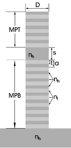
Micropost microcavities consist of a high-refractive-index region (spacer) sandwiched between two dielectric mirrors, as shown in Fig. 1. Confinement of light in these structures is achieved by the combined action of distributed Bragg reflection (DBR) in the longitudinal direction (along the post axis), and total internal reflection (TIR) in the transverse direction (along the post cross-section). The microposts analyzed in this paper are rotationally symmetric around the vertical axis. The DBR mirrors can be viewed as one dimensional (1D) photonic crystals generated by stacking high- and low-refractive-index disks on top of each other. The microcavity is formed by introducing a defect into this periodic structure. The periodicity of the photonic crystal is denoted as , the thickness of the low-refractive-index disks is , the diameter of the disks is , and the refractive indices of the low- and high-refractive-index regions are and , respectively. The defect is formed by increasing the thickness of a single high-refractive-index disk from to , as shown in Fig. 1. The number of photonic crystal periods above and below the defect region (i.e., the number of DBR pairs) is labelled as and , respectively.
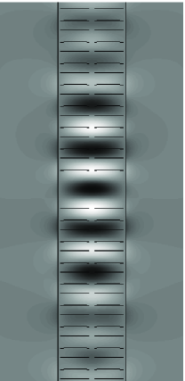
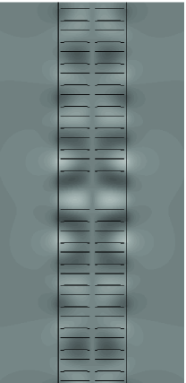
The mode of interest to us is the doubly-degenerate fundamental () mode, whose field pattern is shown in Fig. 2. The parallel component of the electric field is dominant in this mode, and has an antinode in the center of the spacer. Furthermore, in this central plane, the electric field is practically linearly polarized along the vertical axis of the micropost, while there is a small deviation from the linear polarization at larger distances from this axis.
The rule of thumb generally used for designing microposts is to make mirror layers one-quarter wavelength thick, and to choose the optical thickness of the spacer equal to the target wavelength. In the case of a planar DBR cavity (with ), this choice of parameters leads to the maximum reflectivities of the mirrors and the maximum factor of the cavity mode: the cavity operates at the Bragg wavelength, for which the partial reflections from all high- and low-refractive-index interfaces add up exactly in phase. However, the strength of the cavity QED phenomena is proportional to the ratio of the cavity factor to the mode volume , as discussed in the previous section, and we will try to design microposts in such a way that this ratio is maximized.
In our earlier work [22], we analyzed the factor of the mode in a GaAs/AlAs micropost as the cavity diameter was tuned between 0.5 m and 2 m. The remaining cavity parameters were chosen according to the large-cavity rule of thumb, i.e. in such a way that the cavity would operate at the Bragg wavelength for . When the cavity diameter was decreased from 2 m to 0.5 m, the mode volume decreased by a factor of almost ten, from to , while the cavity dropped by only a factor of two, from to . Thus, in order to maximize the ratio of the quality factor to the mode volume , we need to explore structures with small diameters , and try improve their factors.
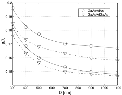
The reduction in with decrease in is due to the combination of two loss mechanisms: longitudinal loss through DBR mirrors, and transverse loss due to imperfect TIR confinement in the transverse direction. Let us address the longitudinal loss first. The decrease in the post diameter implies a change in the dispersion relation of the 1D photonic crystal, and the size and position of its band gap, as illustrated in Fig. 3. In this figure, it is assumed that the high- and low-refractive-index regions of the photonic crystal consist of GaAs and AlAs, with refractive indices of and , and thicknesses of 70 nm and 85 nm, respectively, or that they consist of GaAs and AlxGa1-xAs, with refractive indices of and , and thicknesses of 70 nm and 80 nm, respectively. When the diameter decreases, the frequencies of the band gap edges increase, and the size of the band gap decreases. For structure diameters larger than 2 m, band gap edges can be approximated by their values at . Therefore, as decreases, the blue shift of the cavity mode wavelength increases relative to the target wavelength at which the 1D cavity operates [22]. Simultaneously, the size of the photonic band-gap decreases, implying that the cavity mode is less confined in the longitudinal direction than in the planar cavity case.
The cavity mode is strongly localized in real space, and consequently delocalized in Fourier space (-space), meaning that it consists of a wide range of wave-vector components. Some of these components are not confined in the post by TIR; i.e., they are positioned above the light line, where they can couple to radiative modes, leading to transverse loss. A cavity mode which is strongly confined in the longitudinal direction by high-reflectivity mirrors is delocalized in Fourier space and suffers large transverse loss. Similarly, a mode that is delocalized in the longitudinal direction is more localized in Fourier space and suffers less transverse loss. Therefore, when optimizing the quality factor of three-dimensional microposts, there is a tradeoff between these two loss mechanisms.
In the middle of a large band-gap, the longitudinal confinement is strongest, but the factor is limited by transverse loss. By shifting the resonant wavelength away from the mid-gap (e.g., by tuning the thickness of the cavity spacer) one can delocalize the mode in real space, localizing it more strongly in Fourier space, reducing the contribution of wave-vector components above the light line, and thereby decreasing the transverse radiation loss. Eventually, as the mode wavelength approaches the band-gap edges, the loss of longitudinal confinement starts to dominate and drops. Therefore, in the microposts with high reflectivity mirrors and finite diameter, it is expected that the maximum will be located away from the mid-gap position.
Moreover, since the mode wavelength can be tuned from the mid-gap towards any of the two band-gap edges, two local maxima of (i.e., a double peak behavior in vs. mode wavelength) are expected. Besides detuning the mode wavelength from the mid-gap, we can also suppress the transverse loss by relaxing the mode slightly in the longitudinal direction, i.e., by reducing the reflectivities of photonic crystal mirrors and decreasing the band gap size. This can be achieved by shrinking the cavity diameter, or by changing the photonic crystal parameters (e.g., by reducing the refractive-index contrast).
In this article, we study both of these approaches to optimization: tuning the mode wavelength away from the mid-gap by changing the spacer thickness, and tuning the mirror reflectivities by changing photonic crystal parameters or cavity diameter. We also show that the employment of very high reflectivity mirrors cannot lead to high- cavities with small diameters, as the transverse radiation loss is high, resulting from very strong mode localization in the longitudinal direction.
4 Maximizing the ratio of quality factor to mode volume for the fundamental mode in a micropost microcavity
4.1 Tuning the cavity diameter and the cavity spacer
In our earlier work [22], we analyzed the factor of the mode in a GaAs/AlAs micropost as the cavity diameter was tuned between 0.5 m and 2 m. The remaining cavity parameters were chosen in such a way that the cavity would operate at the Bragg wavelength for ( nm, nm, nm, and ). The number of DBR mirror pairs on top and bottom were and , respectively.
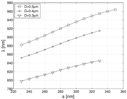
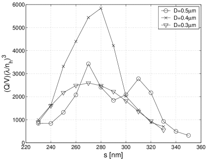
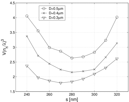
Let us first study the mode as the diameter is decreased below 0.5 m, keeping all other structure parameters the same as above. In order to tune the mode frequency within the band gap, we tune the spacer thickness . Results for , , , and are shown in Figs. 4 and 5. From Fig. 3, we see that the band gaps in these structures extend from 875 nm to 969 nm, from 850 nm to 920 nm, and from 790 nm to 850 nm, for structure diameters of 0.5 m, 0.4 m, and 0.3 m, respectively. As we have noted previously, when decreases, the band gap edges shift towards lower wavelengths, and the size of the band gap decreases. The cavity mode wavelength is blue-shifted in this process, as can be seen in Figure 4.
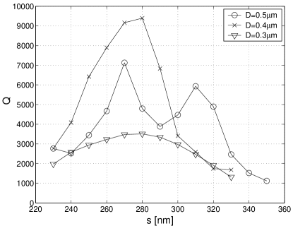
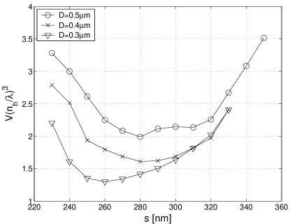
The mode volume is minimized when the mode wavelength is located near the middle of the band gap. For the structures with equal to 0.4 m and 0.3 m, the maximum factor also occurs close to the mid-gap. Different behavior is seen for the structure with equal to 0.5 m, which has a local minimum of at mid-gap and exhibits a double-peak behavior.
The double-peak behavior was already introduced in the previous section. In the middle of the band gap, where the longitudinal mode confinement is strongest and the mode volume is minimum, the radiation loss in the transverse direction is high, and the factor is degraded. By shifting the resonant wavelength away from the mid-gap, the mode is delocalized in real space, leading to a reduction in the transverse radiation loss (e.g., at the positions of the two peaks in ). Eventually, as the mode wavelength approaches the band-gap edges, the loss of longitudinal confinement starts to dominate, drops, and the mode volume increases.
To support this explanation, we analyze the same structure, with m, but with the number of mirror pairs on top () increased from to . As expected, at mid-gap, does not increase significantly with . The mode there is already strongly confined in the longitudinal direction, and the addition of extra pairs does not change the longitudinal loss. The modal factor is determined by the radiation loss in the transverse direction, which is independent of . On the other hand, the ’s at the two peaks increase with . At these points, the mode is not confined as well in the longitudinal direction, and longitudinal loss can be reduced by adding more mirror pairs.
As an even stronger demonstration of our explanation for the double-peak behavior, we separate the radiation loss into the loss above the top micropost surface (), and the loss below it (). The total is a combination of two newly introduced quality factors, and , which are inversely proportional to and , respectively:
| (8) |
It follows from their definition that and are measures of the longitudinal and transverse loss, respectively. We analyze two sets of structure parameters, corresponding to the local maximum or minimum in . For nm and m (local maximum), we calculate and , while, for nm and m (local minimum), we calculate and . These results show that the local minimum in is due to an increase in the transverse loss, manifested as a drop in .
Let us now address the single-peak behavior of as a function of cavity spacer thickness, when is equal to 0.4 m or 0.3 m. Structures with smaller diameters have smaller band gaps, as illustrated in Fig. 3, and the cavity modes are more delocalized in the longitudinal direction, relative to the structure with m. The defect modes must therefore be more localized in Fourier space, and will thus suffer less radiation loss in the transverse direction. This implies that the factors are determined mostly by the longitudinal loss. They reach their maxima at the mid-gap, where the mode volume is minimum, and the longitudinal confinement is strongest.
The maximum ratio of almost (where is measured in cubic wavelengths in the high-refractive index material) is achieved for the structure with m. For this structure, the factor is close to , and the mode volume is . For m, a variation in the thicknesses of the mirror layers allows us to achieve a small increase in the factor, to , and in the ratio, to . This result is obtained for nm, nm, and nm.

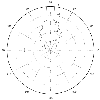
In the introduction, we mentioned that an advantage of microposts, relative to other solid state microcavities, is that the light escapes from them in a single-lobed Gaussian-like pattern, normal to the sample surface. In order to show this, we calculate the far-field radiation pattern from a micropost with m and nm. We are unable to directly compute the far field by employing the FDTD method, as we are limited by our computer memory size. However, we can estimate the far field from the Fourier transform of the near field, using the method described in Ref. [21]. The calculated radiation pattern is shown in Fig. 6. Its resolution is limited by the resolution that we can achieve in Fourier space, or, more precisely, by the number of pixels in the light cone. This, in turn, is dictated by the size of the computational domain. The best resolution in Fourier space that we can obtain with a reasonable size of the computational domain is seven pixels per light cone radius. Nonetheless, the computed radiation pattern demonstrates that even microposts with small diameters can emit light in a Gaussian-like pattern. The FWHM of the emission lobe shown is approximately equal to .
4.2 Other material systems
4.2.1 GaAs/AlxGa1-xAs cavities
In the previous section of this article, we stated that a potential route to maximizing for small micropost diameters is the construction of a photonic crystal with a small refractive-index perturbation. As the perturbation gets smaller, the cavity mode becomes more delocalized in real space, and consequently more localized in Fourier space. This, in turns, leads to reduction in the transverse radiation loss. Furthermore, the cavity resonance can be located at lower frequencies, where the density of free-space radiation modes is smaller. In order to compensate for the increased longitudinal loss, we need to put more mirror pairs on top of these structures.
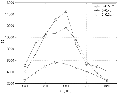
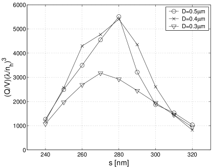
We will now analyze a micropost with the following parameters: nm, nm, , , , and . This choice of refractive indices corresponds to GaAs/AlxGa1-xAs layers. Both the cavity diameter and the spacer thickness are tuned. The positions of the band gap edges as a function of are illustrated in Fig. 3. By comparing to the positions of the band gap edges for the GaAs/AlAs system, we confirm that the band gap in the GaAs/AlxGa1-xAs system is shifted to lower frequencies, and that its size is decreased. This affects the mode dramatically, as can be seen in Figs. 7 and 8.
By comparing Fig. 8 to Fig. 5, we can see that the mode volume increases when the refractive-index contrast is reduced, as a result of the reduction in band-gap size. Even though larger than 14000 can be achieved for m, also increases, and the maximum ratio is similar to that calculated for the GaAs/AlAs system. Furthermore, this ratio can be achieved in the GaAs/AlAs system with fewer top mirror pairs. Longitudinal loss dominates in the GaAs/AlxGa1-xAs system, and vs. plots demonstrate a single-peak behavior.
When the number of mirror pairs on top is reduced from 25 to 20,
the peak factor of the GaAs/AlxGa1-xAs micropost with
diameter of 0.5 m drops from around 14000 to 4000, showing
that the the longitudinal loss is dominant in this case, and a
large number of mirror pairs
is necessary to achieve large factors.
4.2.2 GaAs/AlOx cavities
From the results already presented in this article, it is clear that a material system with a high refractive-index contrast, such as GaAs/AlOx, is not a good choice for high , small mode-volume microposts. High refractive index contrast can certainly produce larger band gaps, and thereby provide a better longitudinal confinement of the cavity mode. However, if the contrast is increased, the mode suffers more radiation loss in the transverse direction, which limits its factor. To confirm this, we analyzed a structure with , , nm, nm, , and , for different . We were unable to obtain good mode localization for m, and the calculated factors were under . For m, the mode has and nm. If we keep increasing to 1.3 m, factors remain below .
5 Cavity quantum electrodynamics with microposts
The question that we would like to address in this section is whether such cavity QED phenomena as strong coupling or single-dot lasing can be observed in the optimized microposts. Let us revisit our best design, with , , m, nm, and the cavity field decay rate GHz.
By combining Eqns. 1 and 4, the Rabi frequency of a system on resonance can be expressed as
| (9) |
where . Let us assume that a quantum dot exciton without a cavity has a typical homogenous linewidth GHz, and a radiative lifetime of 0.5 ns, corresponding to a spontaneous emission rate of GHz. The free-space spontaneous emission rate is GHz. The Rabi frequency for our optimized cavity, calculated from Eqn. 9, is equal to GHz. If we assume that the quantum dot is located in the center of the micropost and that its dipole is aligned with the electric field, we have . Strong coupling is therefore possible in this case, since . The minimum quality factor necessary to achieve strong coupling is approximately equal to 5000. This provides a reasonable margin for degradation due to fabrication imperfections.
Is strong coupling possible with larger diameter microposts, such as m? The mode volume in such a structure is on the order of , as we mentioned previously. For the same quantum dot, with GHz, placed in the center of this large cavity, the Rabi frequency is GHz. For our experimentally observed homogenous broadening GHz, it is impossible to reach strong coupling, since . Even if the homogenous linewidth were reduced to 2 GHz (i.e., if the homogeneous broadening were entirely due to radiative decay), the factor required to achieve strong coupling would be on the order of . We therefore conclude that large-diameter microposts are not promising candidates for the observation of strong coupling with a single quantum dot.
Designs of two-dimensional photonic crystal microcavities in free-standing membranes were recently proposed that allow for very strong coupling between the cavity field and a neutral atom trapped in one of photonic crystal holes [20]. We will now address the feasibility of strong coupling with a single quantum dot in these structures, and compare them to our micropost designs. These photonic-crystal microcavities can localize light into mode volumes equal to , with on the order of . However, since the field intensity is strongest in or around the defect air hole (where a neutral atom would be trapped), it is almost impossible to place a quantum dot at the point where its interaction with the cavity field would be strongest. For example, if the dot is placed at the point where the field intensity is of its maximum value, the Rabi frequency remains the same as for our best micropost design ( GHz), despite a three-fold decrease in the mode volume. The quality factor is in the same range as for the optimized microposts, which implies that the potential of these structures to achieve strong coupling with single quantum dots is similar to that of microposts.
What about single-dot lasing in microposts? The lasing condition for such a microscopic system is given by Eqn. 7. Clearly, in order to reach the laser threshold, it is necessary to increase the Purcell factor and the quality factor . Our analysis indicates that large spontaneous-emission enhancement is possible in microposts. As an example, let us consider an unoptimized microcavity with the following parameters: , , m, nm, nm, nm, , , , nm and . (The method used for calculation is described in Refs. [35] and [36].) The Purcell factor for an emitter with zero linewidth positioned in the center of this micropost, is equal to 147. The enhancement drops to 65 for a linewidth of 100 GHz. Such a high Purcell factor would imply that . Let us also assume that , corresponding to fast pumping. In order to observe single-dot lasing, we then need to satisfy the condition . For a cavity with operating at m, we have ps. Therefore, to achieve single-dot lasing, we would need shorter than ps. If we again assume that the lifetime of an exciton without a cavity is ns, corresponding to a spontaneous emission rate of 2 GHz, lifetime reduction to ps would require a Purcell factor equal to 100. As mentioned above, such Purcell factors are possible for sufficiently narrow homogeneous linewidths. Single-dot lasing should therefore be possible in the optimized microposts.
6 Conclusions
Using the FDTD method, we have analyzed the fundamental () mode in ideal, three-dimensional micropost cavities, for a variety of material systems (GaAs/AlAs, GaAs/AlxGa1-xAs and GaAs/AlOx). Microcavities were treated as single defects in a 1D cylindrical photonic crystal, which allowed us to push the limits of quality factors and mode volumes beyond those achievable by standard micropost designs. Our motivation was to maximize the ratio of the defect mode, in order to use cavity-QED phenomena to build novel optoelectronic devices, such as single-dot lasers and high-efficiency light-emitting diodes, or to construct hardware for quantum computers and quantum communication systems, such as single-photon sources and strongly coupled quantum dot – cavity systems.
The standard approach for designing micropost microcavities is to choose the thicknesses of mirror layers and the spacer corresponding to the Bragg wavelength of a planar microcavity. We have shown that this approach does not necessarily lead to the highest factors for the small cavity diameters analyzed in this article ( m). Another widespread misconception is that the of the cavity mode can always be improved by increasing the refractive-index contrast of the mirror layers. We have shown that this approach fails for small post diameters. Two primary loss mechanisms in three-dimensional microposts are the loss in the longitudinal direction, through DBR mirrors, and the loss in the transverse direction, due to imperfect confinement by TIR. A cavity mode which is strongly confined in the longitudinal direction by high-reflectivity mirrors is delocalized in Fourier space, leading to increased coupling to radiation modes and increased transverse loss. Similarly, a mode that is delocalized in the longitudinal direction and suffers significant longitudinal loss is more localized in Fourier space and suffers less transverse loss. When designing three-dimensional microposts, there is a tradeoff between these two loss mechanisms.
We were able to achieve as high as together with mode volume as small as by optimizing structure parameters. Even though this range of values can be achieved in both GaAs/AlAs and GaAs/AlxGa1-xAs material systems, the former is a better choice from the perspective of fabrication, since the optimized structures require fewer mirror pairs on top.
We have also demonstrated that the optimized cavities can be used to observe novel cavity-QED phenomena, such as single-dot lasing or strong coupling between a single quantum dot and the cavity field. Moreover, the potential of microposts to achieve strong coupling with quantum dots is comparable to that of the largest planar photonic crystal microcavities that are presently known [20].
Acknowledgement
This work was supported in part by the ARO, under the research grant 0160-G-BC575 (MURI program entitled “Single photon turnstile devices”). Financial
assistance for M.P. was provided by the Stanford Graduate Fellowships program.
Present address of M. Pelton: Laboratory of Quantum Optics and Quantum Electronics,
Department of Microelectronics and Information Technology, Royal Institute of Technology (KTH),
Electrum 229, SE-164 40 Kista, Sweden.
Address if A. Scherer: California Institute of Technology, Pasadena, CA 91125.
References
- [1] E. M. Purcell. Spontaneous emission probabilities at radio frequencies. Physical Review, 69:681, 1946.
- [2] K. H. Drexhage. Progress in optics, volume 12E, pp.165-232. North-Holland, New York, 1974.
- [3] D. Kleppner. Inhibited spontaneous emission. Physical Review Letters, 47(4):233–236, 1981.
- [4] P. Goy, J. M Raymond, M. Gross, and S. Haroche. Observation of cavity enhanced single-atom spontaneous emission. Physical Review Letters, 50:1903–1906, 1983.
- [5] G. Gabrielse and H. Dehmelt. Observation of inhibited spontaneous emission. Physical Review Letters, 55(1):67–70, 1985.
- [6] F. DeMartini, G. Innocenti, G. R. Jacobowitz, and P. Mataloni. Anomalous spontaneous emission time in a microscopic optical cavity. Physical Review Letters, 59:2955–2958, 1987.
- [7] D. J. Heinzen, J. J. Childs, J. F Thomas, and M. S. Feld. Enhanced and inhibited visible spontaneous emission by atoms in a confocal resonator. Physical Review Letters, 58:1320–1323, 1987.
- [8] Y. Yamamoto, S. Machida, K. Igeta, and Y. Horikashi. Coherence and Quantum Optics, Ed. by J. H. Eberly, L. Mandel, and E. Wolf, page 1249. Plenum, New York, 1989.
- [9] J. L. Jewell, J. P Harbison, A. Scherer, Y. H. Lee, and L. T Florez. Vertical-cavity surface-emitting lasers – design, growth, fabrication, characterization. IEEE Journal of Quantum Electronics, 27:1332–1346, 1991.
- [10] S. L. McCall, A. F. J. Levi, R. E. Slusher, S. J. Pearton, and R. A. Logan. Whispering-gallery mode microdisk lasers. Applied Physics Letters, 60:289–291, 1992.
- [11] E. Yablonovitch. Inhibited spontaneous emission in solid-state physics and electronics. Physical Review Letters, 58:2059–2062, 1987.
- [12] S. John. Strong localization of photons in certain disordered dielectric superlattices. Physical Review Letters, 58:2486–2489, 1987.
- [13] T. Baba. Photonic crystals and microdisk cavities based on GaInAsP-InP system. IEEE Journal Of Selected Topics in Quantum Electronics, 3:808–830, 1997.
- [14] J. S. Foresi, P. R. Villeneuve, J. Ferrera, E. R. Thoen, G. Steinmeyer, S. Fan, J. D. Joannopoulos, L. C. Kimerling, H. I. Smith, and E. P. Ippen. Photonic bandgap microcavities in optical waveguides. Nature, 390:143–145, 1997.
- [15] G. S. Solomon, M. Pelton, and Y. Yamamoto. Single-mode spontaneous emission from a single quantum dot in a three-dimensional microcavity. Physical Review Letters, 86(17):3903–3906, 2001.
- [16] C. J. M. Smith, H. Benisty, D. Labilloy, U. Oesterle, R. Houdre, T. F. Krauss, R. M. De La Rue, and C. Weisbuch. Near-infrared microcavities confined by two-dimensional photonic bandgap crystals. Electronics Letters, 35(3):228–230, 1999.
- [17] C. Reese, C. Becher, A. Imamoglu, E. Hu, B. D. Gerardot, and P. M. Petroff. Photonic crystal microcavities with self-assembled InAs quantum dots as active emitters. Applied Physics Letters, 78:2279–2281, 2001.
- [18] T. Yoshie, A. Scherer, H. Chen, D. Huffaker, and D. Deppe. Optical characterization of two-dimensional photonic crystal cavities with indium arsenide quantum dot emitters. Applied Physics Letters, 79:114–116, 2001.
- [19] T. Yoshie, J. Vučković, A. Scherer, H. Chen, and D. Deppe. High quality two-dimensional photonic crystal slab cavities. Applied Physics Letters, 79:4289–4291, 2001.
- [20] J. Vučković, M. Lončar, H. Mabuchi, and A. Scherer. Design of photonic crystal microcavities for cavity QED. Physical Review E, 65:016608/1–11, 2001.
- [21] J. Vučković, M. Lončar, H. Mabuchi, and A. Scherer. Optimization of Q factor in microcavities based on free-standing membranes. IEEE Journal of Quantum Electronics, 38(7):850–856, July 2002.
- [22] M. Pelton, J. Vučković, G. S. Solomon, A. Scherer, and Y. Yamamoto. Three-dimensionally confined modes in micropost microcavities: Quality factors and Purcell factors. IEEE Journal of Quantum Electronics, 38(2):170–177, 2002.
- [23] Y. Yamamoto and A. İmamoḡlu. Mesoscopic quantum optics. John Wiley & Sons, Inc., New York, 1999.
- [24] K. An, J. J. Childs, R. R. Dasari, and M. S. Feld. Microlaser: A laser with one atom in optical resonator. Physical Review Letters, 73:3375–3378, 1994.
- [25] G. Björk, A. Karlsson, and Y. Yamamoto. Definition of a laser threshold. Physical Review A, 50:1675–1680, 1994.
- [26] C. Santori, M. Pelton, G. Solomon, Y. Dale, and Y. Yamamoto. Triggered single photons from a quantum dot. Physical Review Letters, 86(8):1502–1505, 2001.
- [27] P. Michler, A. Kiraz, C. Becher, W. V. Schoenfeld, P. M. Petroff, L. Zhang, E. Hu, and A. Imamoğlu. A quantum dot single-photon turnstile device. Science, 290:2282–2285, 2000.
- [28] E. Moreau, I. Robert, J. M. Gérard, I. Abram, L. Manin, and V. Thierry-Mieg. Single-mode solid-state single photon source based on isolated quantum dots in pillar microcavities. Applied Physics Letters, 79(18):2865–2867, 2001.
- [29] C. H. Bennet and G. Brassard. Proceedings of the IEEE International Conference on Computers, Systems and Singnal Processing. IEEE, Bangalore, India, 1984.
- [30] Y. Yamamoto, M. Kitagawa, and K. Igeta. Proceedings of 3rd Asia-Pacific Physics Conference, Ed. by Y. W. Chan et al., page 779. World Scientific, Singapore, 1988.
- [31] E. Knill, R. Laflamme, and G. J Milburn. A scheme for efficient quantum computation with linear optics. Nature, 409:46–52, 2001.
- [32] H. Mabuchi, M. Armen, B. Lev, M. Lončar, J. Vučković, H. J. Kimble, J. Preskill, M. Roukes, and A. Scherer. Quantum networks based on cavity QED. Quantum Information and Computation (Special Issue on Implementation of Quantum Computation), 1:7–12, 2001.
- [33] A. Stefanov, N. Gisin, L. Guinnard, and H. Zbinden. Optical quantum random number generator. Journal of Modern Optics, 47:595–598, 2000.
- [34] T. Jennewein, U. Achleitner, G. Weiss, H. Weinfurter, and A. Zeilinger. A fast and compact quantum random number generator. Rev. Sci. Inst., 71:1675–1680, 2000.
- [35] J. Vučković, O Painter, Y. Xu, A. Yariv, and A. Scherer. Finite-difference time-domain calculation of the spontaneous emission coupling factor in optical microcavities. IEEE Journal of Quantum Electronics, 35(8):1168–1175, 1999.
- [36] Y. Xu, J. Vučković, R. Lee, O Painter, A. Scherer, and A. Yariv. Finite-difference time-domain calculation of the spontaneous emission lifetime in a microcavity. Journal of the Optical Society of America B, 16:465–474, 1999.