Surpassing the standard quantum limit for optical imaging using non-classical multimode light
Abstract
Using continuous wave superposition of spatial modes, we demonstrate experimentally displacement measurement of a light beam below the standard quantum limit. Multimode squeezed light is obtained by mixing a vacuum squeezed beam and a coherent beam that are spatially orthogonal. Although the resultant beam is not squeezed, it is shown to have strong internal spatial correlations. We show that the position of such a light beam can be measured using a split detector with an increased precision compared to a classical beam. This method can be used to improve the sensitivity of small displacement measurements.
pacs:
42.50.Dv, 42.50.Lc, 42.30.-dIt has long been known that optical measurements are ultimately limited in their sensitivity by quantum noise, or shot noise, of the light. For more than a decade the usage of nonclassical light has provided ways of improving the sensitivity beyond this standard quantum limit Bachor . For example, squeezed light has been used to improve interferometric Interf and absorption Absor measurements. However, these improvements can only be applied to signals that correspond to the time modulation of light, as they rely on the temporal quality of the light. On the other hand, many applications require spatial measurement of light. While improvements for spatial applications based on non-classical light have been proposed theoretically Seng ; Fabre , no experimental demonstration has yet been shown to work with continuous wave light. The challenge is to create strong spatial correlations within a laser beam, rather than the temporal correlation typically found in non-classical light sources kolobov . While some experiments involving sub-Poissonian VCSELS operating in a transverse multimode regime exhibited a non-random spatial distribution of the quantum noise VCSELS , no spatial correlation was observed within the produced beam. Here we present the first successful experimental demonstration of a spatially ordered light source and a measurement of the spatial modulation of a laser beam position to below the standard quantum limit in the continuous wave regime.
This experimental work builds on theoretical work done on non-classical multimode states of light Lugiato2 . Such states display strong spatial correlations, and their productions have been the subject of extensive studies in recent years kolobov3 . In particular, the process of parametric down-conversion in a nonlinear optical medium has been extensively studied, as it produces “twin photons” which are quantum correlated both temporally and spatially. Such strong spatial quantum correlations in the plane perpendicular to the direction of propagation are produced in spontaneous down-conversion Teich and in multimode transverse optical parametric oscillators Lugiato . Nevertheless, to our knowledge, there has been no experimental demonstration of quantum correlations with a multimode transverse light in the continuous wave regime.
Precision optical imaging using CCD cameras or photodetector arrays is required in many areas of science, ranging from astronomy to biology. Ultimately, the performance of optical imaging technology is limited by quantum mechanical effects. Of particular importance, as far as applications are concerned, is the measurement of image displacements, for example, the position of a laser beam. Techniques that rely on determining the position of a laser spot include atomic force microscopy AFM , measurement of very small absorption coefficients via the mirage effect Boccara and observation of the motion of single molecules biologie . These measurements are usually performed as shown in Fig. 1.
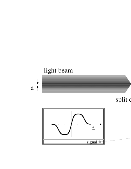
The beam is incident on a split detector that delivers two currents proportional to the light intensity integrated over the two halves ( and ) of the image plane. If the beam is initially centered on the detector, the mean value of the photocurrent difference is directly proportional to the relative displacement of the beam with respect to the detector. With a classical, shot noise limited laser source, the smallest displacement that can be measured (with a signal-to-noise ratio of one) is shown to be Fabre
| (1) |
Here is the total number of photons recorded by the two detectors during the measurement time, and is the local density of photons (photons per unit transverse length) at the position of the boundary between the two detectors. For a TEM00 Gaussian beam with radius , the minimum measurable displacement is found to be
| (2) |
For maximum focusing of the Gaussian beam, , and we obtain , which is the absolute minimum displacement of a physical system that can be measured with classical beams AFM . Equation (2) shows that a more powerful laser, or a longer measurement time, gives increased measurement precision. However, in many applications these alternatives are simply not practical. In the case of atomic force microscopy, for example, excessive laser power ultimately leads to radiation pressure noise FM . For biological applications, large laser power may damage the samples under investigation and an increased integration time leads to loss of bandwidth. This is the motivation for looking for alternative methods of increasing measurement precision.
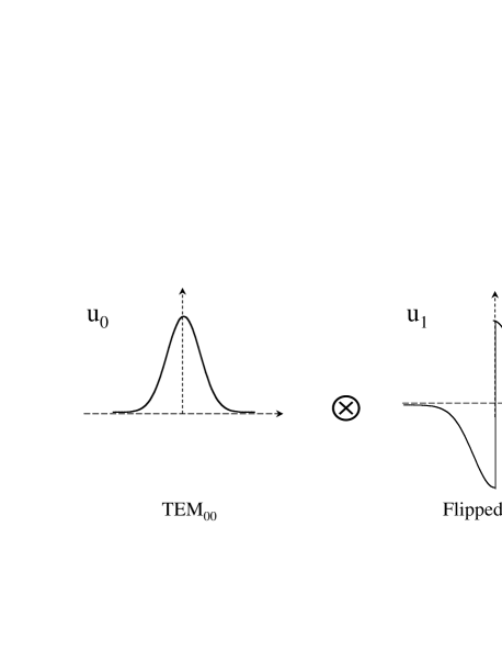
The limit of equation (2) can be surpassed only using multimode non-classical light. Let us consider a beam of light with an electric field distribution given by . We can build an orthonormal basis of the transverse plane such that is the first vector; is a “flipped” mode, given by for and for (see Fig. 2); and the other modes are choosen in order to form a basis. In this basis, the mean field of our light lies only in the first mode but, a priori, all of the modes contribute to the quantum noise. In order to determine the relevant modes of our measurement, we consider the interference quantities between two modes on each half of the split detector:
| (3) |
Then the interference quantities relevant for a total measurement (sum of the two photodetectors) and a differential measurement (difference of the two photodetectors) can be written:
| (4) |
One can then show that for any transverse mode ,
| (5) |
Since all , for , are orthonormal to (i.e. ), equation (5) demonstrates that these modes have a zero overlap integral with in a differential measurement. It can then be shown that only , which has a non-zero overlap integral with , has to be considered along with in the noise calculation Fabre ; Delaubert .
We note that the modes and have perfect interference visibility as shown by their complete overlap integral for the differential measurement, ie. . In this regard, the measurement is analogous to a perfect homodyne measurement with a beam splitter. The two modes are equivalent to the two input beams of a beamsplitter and the two halves of the multimode beam are equivalent to the two outputs. Therefore, similar to a homodyne measurement, the noise on the differential measurement is completely cancelled when the flipped mode is occupied by a perfect squeezed vacuum, with the squeezed quadrature in phase with the coherent field of the mode. Conversely, the same result is also obtained when the mode profiles of the squeezed and the coherent fields are interchanged. In order to avoid the effect of losses, we have chosen a squeezed vacuum mode . We would like to stress that this simplified explanation can be applied only because we have conveniently identified the two relevant transverse modes of the measurement. However, contrary to a homodyne measurement, the entire measurement is performed using a single beam. Furthermore, a more general analysis is not limited to only two-mode beams.
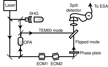
The experimental setup is shown in Fig. 3. A stable Nd:YAG 700 mW laser provides a cw single mode beam at 1064 nm. A part of this beam is sent to a locked MgO:LiNbO3 frequency doubling cavity. The 532 nm output of the frequency doubler is used to pump a degenerate optical parametric amplifier (OPA) that produces a stable 10 W squeezed beam in the TEM00 mode at 1064 nm. The noise reduction of the OPA output is measured to be 3.5 dB. Details of this squeezing system may be found in Buchler . The flipped mode, , is produced by sending the remaining part of the initial 1064 nm laser beam through a specially designed phase plate. This phase plate consists of two birefringent half-wave plates, one rotated by 90∘ with respect to the other, forming the two halves and of the transverse plane. These elements introduce a phase shift of 180∘ between the field amplitudes of the two halves. The squeezed output from the OPA is required to be superimposed onto the flipped mode with minimal loss. This is achieved by using a beam splitter that reflects 92% of the squeezed state and transmits 8% of the coherent state. The reflected output is then sent to a quadrant InGaAs detector (EPITAXX 505Q) with quantum efficiency greater than 90%. Only two of the four quadrants, of dimensions 500m 500m each and with a dead zone between the pixels of m, are used in this experiment. A lens of focal length 30mm is used to image the phase plate on the detector plane and to counteract the diffraction of the flipped mode, which undergoes an abrupt phase change and therefore contains high spatial frequency components.
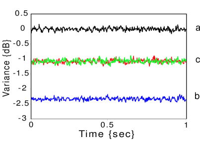
Fig. 4 shows the different noise levels monitored as a function of time when the relative phase between the coherent state and the squeezed state is chosen for maximum noise reduction. Due to the high stability of the various servo-loops in the experimental setup, the actively locked operation of the setup can be kept for hours. The noise measured on the sum of the two halves (Fig. 4a), i.e. on the total beam, coincides with the shot noise level for the conditions of this experiment, as expected from the coherent beam, which is not affected by the presence of a squeezed vacuum in an orthogonal mode. The noise measured on each individual half (Fig. 4c) is reduced by 1.08 0.06 dB below the quantum noise limit. The fact that the intensity noise on each half of the beam is below the quantum noise limit, whereas the whole beam is at shot noise, shows the strong non-classical characteristic of this multimode beam. This is corroborated by the experimental data of Fig. 4b, which gives the noise on the intensity difference between the two halves at 2.34 0.05 dB below the quantum limit. The results suggest that the beam is made of two strongly quantum correlated parts, indicating that a significant amount of spatial correlation has been created among the photons. With the measured noise reduction in the squeezed vacuum and a perfect setup (i.e. a perfect phase plate and a perfect mode-matching between the two transverse modes), one would expect 2.5 0.2 dB of noise reduction on the difference between the two pixels. This demonstration is, to our knowledge, the first experiment in which spatial quantum effects have ever been observed in a bright beam of light.
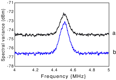
This spatial noise correlation can now be used to improve the precision of displacement measurements in the image plane. For practical reasons, we have choosen to induce the displacement only in the coherent mode, before the mixing on the beamsplitter. However this displacement is of the order of the nanometer, which is several order of magnitude smaller that the relevant precision for the mode-matching of the two transverse modes, and the theoretical prediction for the measurements is the same as if the displacement was done on the total beam. In order to produce a small controllable beam displacement in the frequency range of the previous measurements, we use two electro-optic modulators (EOMs) driven at 4.5 MHz. Fig. 3 shows that EOM2 is slightly tilted with respect to the propagation of the light beam. When a voltage is applied across EOM2, a change in refractive index is induced and the transmitted beam experiences a parallel transverse displacement measured at about 3nm/V. We introduce a modulation at 4.5 MHz as signal for our displacement measurement which can be easily distinguished from the low frequency beam displacements induced by mechanical or acoustic vibrations. Apart from the parallel displacement, EOM2 will also introduce an unwanted phase modulation on the transmitted beam which is detrimental to our measurement. EOM1 of Fig. 3 is therefore used to compensate for this introduced phase modulation. When correct gains are chosen for both modulators, the transmitted beam will not have any phase or amplitude modulation and is only left with pure transverse displacement modulation. Figure 5 shows the differential signal monitored by a spectrum analyzer when the light beam undergoes a displacement modulation with an amplitude of 2.9Å. With a resolution bandwidth of 100 kHz, our setup recorded a modulation peak in the Fourier spectrum. Fig. 5a shows the trace when vacuum instead of the squeezed vacuum is used in mode . Thus this noise floor gives the standard quantum limit in such a displacement measurement. The signal-to-noise ratio (SNR) of this measurement is 0.68. When the two-mode non-classical beam is utilized in the measurement (Fig. 5b), we obtain a SNR of 1.20. This gives an improvement of the displacement measurement sensitivity by a factor of 1.7. The result is in agreement with the theoretical value calculated with the noise reduction reported in the previous paragraph. Similar measurements have been performed with a 10 kHz resolution bandwidth (and therefore a longer measurement time) and the results show the same improvement of the SNR.
Our results demonstrate that multimode non-classical states of light can be utilized to improve the optical measurement of small displacements. The noise floor of displacement measurements can actually be reduced to below the standard quantum limit. Of particular relevance are the potential usage of multimode squeezed light in atomic force microscopy and biological microscopy. Though our experimental demonstration is restricted to one-dimensional displacement measurements, it can be extended to two-dimensional displacement measurements with more complex forms of multimodal non-classical light.
Acknowledgements.
We would like to thank L. Lugiato and M. Kolobov for many enlightening discussions and CSIRO, Sydney, for the manufacturing of the special phase plate. This work is funded by the European project IST-2000-26019 ”Quantum images”, the Centre National de la Recherche Scientifique and the Australian Research Council.References
- (1) H-A Bachor, a guide to experiments in quantum optics. (Wiley-VCH, Weinheim, 1998).
- (2) M. Xiao, L.A. Wu and H.J. Kimble, Phys. Rev. Lett. 59, 278 (1987); P. Grangier et al., Phys. Rev. Lett. 59, 19 (1987)
- (3) E. Polzik, J. Carri and H.J. Kimble Appl. Phys B 55, 279 (1992); F. Marin, A. Bramati, V. Jost and E. Giacobino, Optics Commun. 140, 146 (1997).
- (4) C. Fabre, J.B. Fouet and A. Maître, Optics Letters 25, 76-78 (1999).
- (5) Seng-Tiong Ho, P. Kumar and J.H. Shapiro, Phys. Rev. A 37, 2017 (1988).
- (6) M. Kolobov and C. Fabre, Phys. Rev. Lett. 85 3789 (2000).
- (7) J.P. Poizat, T. Chang, P. Grangier, Phys. Rev. A 61, 043807 (2000); J.P. Hermier et al., IEEE JQE, 37, 87 (2001)
- (8) M.I. Kolobov, Rev. Mod. Phys. 71,1539 (1999).
- (9) L.A. Lugiato, A. Gatti and H. Wiedemann in Quantum Fluctuations, Proceedings of the Les Houches Summer School of Theoretical Physics, p431, (North-Holland, Amsterdam, 1997).
- (10) C.A.J. Putman et al. , Journ. of Applied Phys. 72, 6 (1992).
- (11) D.P.E. Smith, Rev. Sci. Instrum. 66, 3191 (1995).
- (12) C. Boccara, D. Fournier and J. Badoz, Appl. Phys. Letters 36, 130 (1980).
- (13) H. Kojima et al., Biophysical Journal 73, 2012 (1997).
- (14) A. Joobeur et al., Phys. Rev. A 53, 5349 (1996).
- (15) L.A. Lugiato and I. Marzoli, Phys. Rev A 52, 4886 (1995); I. Marzoli A. Gatti and L.A. Lugiato, Phys. Rev. Lett. 78, 2092 (1997)
- (16) V. Delaubert et al., (submitted to J. Opt. A, Aug. 2001).
- (17) B.C. Buchler et al., Phys. Rev. A, 65, 011803(R) (2002).