Quantum Theory and Classical Information
Where there is quantum theory there is hope
Quoted from Joyce Carol Oates What I lived for
Abstract
Transmission of classical information using quantum objects such as polarized photons is studied. The classical (Shannon) channel capacity and its relation to quantum (von Neumann) channel capacity is investigated for various receiver arrangements.
A quantum channel with transmission impairment caused by attenuation and random polarization noise is considered. It is shown that the maximal (von Neumann) capacity of such a channel can be realized by a simple symbol by symbol detector followed by a classical error correcting decoder.
For an intensity limited optical channel capacity is achieved by on-off keying (OOK). The capacity per unit cost is shown to be 1 nat/photon = 1.44 bit/photon, slightly larger than the 1 bit/photon obtained by orthogonal quantum signals.
1 Introduction
In his fundamental work [1] A Mathematical Theory of Communications from 1948 Claude Shannon introduced the quantity
which he called “entropy”. It plays a central role in information theory as a measure of information, choice and uncertainty.
Richard P. Feynman tells [2] that Shannon adopted this term on the advice of John von Neumann, who declared that it would give him “ … a great edge in debates because nobody really knows what entropy is anyway”.
At MIT in the early 1960-ties Claude Shannon told me and the other students in Course 6.575 that he choose the name because his expression had the same form as that of entropy in statistical mechanics. He also said that he doubted that information theory has any physical relation to thermodynamics.
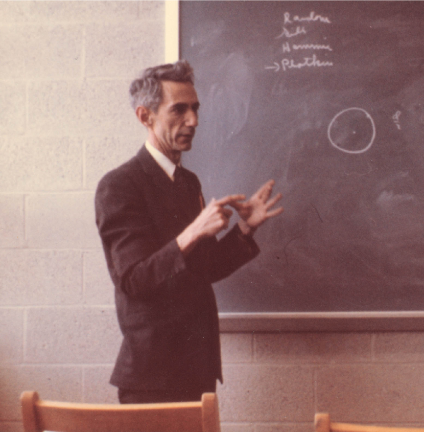
Claude E. Shannon, MIT Course 6.575, April 17, 1961.
Photo: Göran Einarsson
One of the principal works on quantum theory is Mathematische Grundlagen der Quantenmechanik [3] by Johann von Neumann published in Berlin 1932, before he changed his first name to John. There he introduced the concept of quantum entropy
The motivation was of course thermodynamics, there was no information theory around at that time.
More recently it has been shown by A. S. Holevo and others, that the von Neumann entropy S plays a fundamental role in quantum information theory just as the Shannon entropy H in classical information theory.
Quantum Information Theory is an interesting and expanding field. The basic applications of classical information theory such as source coding, data compression and channel coding have counter parts in quantum theory. Most of today research is focused on coding and transmission of quantum states motivated by the connection to quantum computing.
We deal here with transmission of classical information by quantum objects.
2 Basic Quantum Theory
A pure quantum state is represented by a normalized vector in a
Hilbert space. We consider polarized photons in
a two-dimensional space.
A ‘ket’ is a column vector
with complex components and and normalization
The ‘bra’ is the complex transpose of i. e. the row vector
An important feature of a Hilbert space is the scalar product called the ‘braket’. For
the scalar product is
A two-dimensional quantum state representing one bit of information and is called a qubit.
Consider polarized photons an let denote the state of horizontal and vertical polarization. These two states are orthogonal, i. e. their scalar product is equal to zero, and arbitrary polarization states can be expressed as a weighted sum of these. The state
denotes 45 degree polarization and
is right hand side circular polarization.
The scalar product between states plays an important role in the sequel. By direct calculations it is easily shown that and .
3 Communication of Classical Information
3.1 Binary Signaling
We consider the possibility of communicating classical information, i.e. ordinary data expressed as binary digits ‘one’ and ‘zero’ utilizing quantum objects such as polarized photons.
As an example let the transmitter produce photons in two polarization states and shown in Fig. 2.
The transmitted signals have either horizontal or 45 degree polarization.
The receiver determines which type of photon was sent by a suitable measuring device (receiver). As a first attempt let the receiver consist of a horizontally oriented polarization filter.
A photon in state will pass the receiver filter with certainty while a photon in state will pass with probability
This means that the communication system is equivalent to the discrete binary Z-channel, shown in Fig. 2.
Binary photon communication with horizontal
polarization receiver.
a) Transmitted states and .
b) Resulting discrete binary Z-channel.
The Shannon channel capacity of a memoryless discrete channel with input alphabet and output alphabet is equal to the maximum of the average mutual information between sender and receiver [4]
| (1) |
The quantity denotes the probability of input symbol and is the transition probability between input symbol and output symbol . Channel capacity defined as maximized over all possible input symbol probability assignments For a Z-channel with two input and output symbols can be obtained by a straightforward optimization. A convenient way of evaluating is to use the general expression for two-dimensional channels presented in [5]. For the Z-channel in Fig. 2 the optimal input distribution is and reflecting that the input symbol is more reliable than the symbol and should be used more frequently in the code achieving capacity. The numerical value is
A relevant question is whether the horizontally oriented polarization receiver is the best possible choice. There is a better alternative. It has been shown [6] that a the filter orientation shown in Fig. 3 minimizes the probability of making an incorrect decision.
Binary photon communication with optimal
polarization receiver.
a) Transmitted states and
. Receiver orientation
and .
b) Resulting discrete binary symmetric channel.
In this case it also maximizes the Shannon capacity. The resulting discrete channel is symmetric with
where is the transition probability and
| (2) |
is the binary entropy function.
3.1.1 POVM Receiver
The discrete classical channels arrived at in the preceding section depend on the receiver configuration. The receivers in Fig. 2 – 3 perform simple quantum tests, they check if the received photon is in any of two orthogonal polarizations, which is the best that can be done operating in an isolated two dimensional Hilbert space.
A more general type of measurement is a POVM (Positive Operator Valued Measure). In the present context it is accomplished by extending the original two-dimensional Hilbert space combining the received photon with a so called ancilla which is a photon in a known fixed state. The received photon and the ancilla represent four dimensions together, which makes a test between four orthogonal states possible. This way it is possible to test if or were transmitted. Such a decision can not be made with certainty and the receiver will now also produce a no decision output.
The principle of a POVM receiver for two signals separated by 45 degrees is illustrated in Fig. 4. The idea is to create three orthogonal state vectors , and in the extended Hilbert space, such that the projections of two of them falls on the signal vectors and . In the present situation it is not possible to project directly on these and the projections are made on the vectors and orthogonal to and .
| Binary erasure channel generated by a POVM receiver. | |
| a) | Transmitted states and together with the orthogonal |
| POVM states , and in three dimensional space. | |
| b) | Resulting discrete binary erasure channel, . |
From the geometry follows
with The output symbol probabilities when, say , is transmitted are given by the square correlations between and , and respectively.
The receiver bases its decision on the projections in the original two-dimensional space making its measurements on the received polarized
3.2 von Neumann Capacity
The receivers in Fig. 2 – 4 make decisions on each received symbol separately, they perform hard decisions. In general the channel capacity can be improved by making decisions based on a sequence of received symbols. Holevo showed [7] that the capacity for transmission of classical information over a quantum channel is upper bounded by
| (3) |
The transmitter sends on of possible states characterized by their density matrices . The states may be pure or mixed. State has input probability and is the average density matrix . The function is the von Neumann entropy
| (4) |
It has recently been proved that the Holevo upper bound (3) actually defines capacity, i.e. it can be achieved. This result is known as the Holevo-Schumacher-Westmoreland (HSW) Theorem, see [8].
For pure input states and (3) reduces to
| (5) |
For the signal configuration in Fig. 2 the density matrices are
and
Equal input probabilities gives
Substitution into (5) gives the von Neumann capacity for communication with two photons differing 45 degrees in polarization
The maximal value can achieve is which is obtained by orthogonal signals, e.g. = and = . In this case and the the limit of 1 bit per photon is reached in a trivial way.
3.3 Ternary signaling
There is no need to restrict the communication to binary transmission. The following example of a ternary quantum signal alphabet has been investigated by Peres and Wootters [9] and implemented by Clarke et al. [10]. The transmitted photon is on one of three symmetrical polarizations apart shown in Fig. 5a.
Ternary signals.
a) Transmitted states ,
and .
b) POVM vector projections parallel to the signals.
c) POVM vector projections orthogonal to the signals.
The von Neumann capacity (5) for this signal set is equal to the maximally possible .
A POVM receiver utilizing an ancilla photon, analogous to the one described in Section 3.1.1 is needed to be able to distinguish between the three transmitted alternatives. A natural choice is to let POVM projections fall on the input signals, which would correspond to a matched filter receiver in classical communication theory. The resulting discrete channel is shown in Fig. 5b. Its Shannon capacity is bit/photon. This receiver maximizes the probability of detecting the correct signal.
A better alternative, however, is to let the POVM projections be orthogonal to the input signal. This results in the channel in Fig. 5c with bit/photon.
The Shannon capacity requires a maximization over the input symbol alphabet. One possibility is to refrain from the use of one of the input symbols, i.e. assign probability zero to it. In the present case the result is a binary channel with two signals separated by or equivalently in polarization. An optimum polarization receiver of the type illustrated in Fig. 3 generates a binary symmetric channel with and a capacity bit/photon. Which is a larger value than for the ternary signaling systems above and almost as good as the photon pair receiver below.
| Ternary signals with photon pair transmission. | |
| a) | Transmitted states and the orthogonal measurement |
| directions , and in three dimensional space. | |
| b) Resulting discrete ternary channel. |
An interesting alternative is to let the transmitted signals be a pair of photons with equal polarization. The input alphabet is restricted to the three alternatives and . The von Neumann capacity for this signal set is =1.5/2 = 0.75 bit/photon. It turns out that the transmitted state vectors are almost orthogonal in four-dimensional Hilbert space, see Fig. 6. The corresponding discrete ternary channel has = 1.37 corresponding to 0.68 bit/photon. No ancilla photon arrangement is needed in this receiver.
3.4 Quantum Cryptography
Quantum communication is limited by the fundamental fact that only orthogonal quantum states can be distinguished reliably. In Quantum cryptography [11] the fundamental uncertainty of the outcome of a quantum measurement has been turned into an advantage. Secret information can be communicated safe against eavesdropping.
3.5 Noisy channels
So far we have assumed that an error free channels is available between transmitter and receiver. In practice communication signals are subjected to various types of impairment during transmission. In classical communication noise of different origin is almost always present and has to be included in the analysis.
3.5.1 Attenuation
An common feature in communication systems is signal attenuation. In quantum communication it means that photons or other signal elements are lost on their way from sender to receiver. Attenuation is usually expressed in dB and if an average fraction is lost it corresponds to
If the receiver works in synchronism with the transmitter it can determine when photons are missing and such an event constitutes an erasure. Erasures decrease the capacity of a binary symmetric channel by a factor . As an example let = 10 %, corresponding to = 0.46 dB, the Shannon capacity for the binary communication decreases from = 0.40 to = 0.36 bit/photon. For a system using orthogonal polarizations, which would be error free in case of perfect detection, an attenuation = 1 dB will reduce the capacity from = 1 to = 0.79 bit/photon.
3.5.2 Polarization noise
A more complicated kind of impairment is if the polarization of the photon is disturbed during transmission. If the polarization of the state is changed by an angle during transmission the received density matrix becomes
When is random the received state is a mixed state with density matrix . For polarization noise with a probability density symmetrical around
| (6) |
where
| (7) |
The constant depends on the shape of . For a distribution uniform between and it is equal to and for a Gaussian distribution with variance the quantity .
We consider communication with orthogonal signals and . The received density matrix generated by is
| (8) |
The average density matrix is
and the von Neumann entropy (4) is . The entropies for (6) and (8) are equal to where is the binary entropy function (2). The von Neumann capacity (3) is
For a fixed polarization deviation the system generates a binary symmetric channel (BSC) with transition probability . For a memoryless channel with random the capacity is determined by the average value equal to defined in (7). The Shannon capacity is, for this noisy quantum channel, equal to its von Neumann capacity .
This means that a hard decision symbol by symbol receiver in combination with a classical error correcting code is sufficient to achieve the ultimate capacity of this noisy quantum channel. The choice of orthogonal transmitted signals is essential for this result.
As an example of the effect of polarization noise let . The resulting channel capacities are = = 0.53 bit/photon.
4 Alternative modulation
4.1 Pulse Position Modulation (PPM)
Helstrom [15] suggests a quantum modulation scheme using orthogonal states generated as longitudinal modes in an ideal laser. The signaling is done by exciting one of these modes into a coherent state. It is shown that the error probability goes to zero for increasing , which means that the channel have infinite capacity. He remarks that ‘the quantum-mechanical nature of signals themselves does not limit the information-carrying capacity of a coherent optical channel’.
To cast some light on this seemingly impossible result consider a semi-classical model of optical communication, the Poisson channel. It models light as a random stream of photons characterized by the optical intensity [14]. The number of photons in a time interval has a Poisson distribution
with mean value
In quantum terminology the light is in a coherent state.
A set of orthogonal optical signals is generated by dividing the transmission interval of duration into time slots each of width . An pulse of limited optical energy is transmitted in one of the time slots. This modulation format called Pulse Position Modulation (PPM) is shown in Fig 7a. for the ideal case with the background optical intensity .
a) Optical pulse position modulation (PPM) with
time slots.
b) Channel diagram for an ideal optical PPM channel
with .
With this assumption, the only situation when a transmission error can occur is when, due to the Poisson fluctuations, no photons are observed in the interval . The ideal PPM channel is equivalent to an M-ary erasure channel, shown in Fig 7b. The probability for an erasure is
where is the average number of transmitted photons. The capacity for the M-ary erasure channel is
The channel capacity for optical PPM approaches when . It can be shown [16] that this is true also when . In practice the time slots can not be made arbitrary small since optical bandwidth is limited. In PPM the optical pulses have optical intensity which is assumed to be unlimited.
4.2 On-Off Keying (OOK)
For an optical system with constrained signal intensity
it has been proved [18] that
on-off keying (OOK) is the optimal modulation format.
With the
channel capacity, in natural units per second, is [17],
[18], [19]
| (9) |
The background optical intensity typically represents
the dark current in the receiver photo detector.
For the ideal case the expression reduces to
| (10) |
The maximal error free transmission capability, channel capacity, is usually expressed as information per unit time (bit/s or nat/s). An alternative measure is capacity per unit cost [22]. For optical transmission a natural cost function is the number of photons needed to reliably transmit one bit of information.
The capacity (9) is achieved when the ‘on’ symbol is used with probability
| (11) |
The average intensity of signal photons is
| (12) |
The capacity per unit cost in nat per photon becomes
| (13) |
Fig 8 shows the cost per bit i.e. as a function of for a system with . The diagram is equivalent to Fig 1 in [22] for an AWGN channel. For large the capacity approaches the asymptotic value . In Fig 8 the asymptotic value = 1/1.44 is indicated.
quant-ph \psfrag{gamma1 photons/s}{$\gamma_{1}$ \ \ \ \ photons/s }\psfrag{cost/bit}{\large cost/bit}\psfrag{ln 2}{ln 2}\psfrag{gamma0=1}{$\gamma_{0}=1$}\includegraphics[width=433.62pt]{Fig8.eps}
Intensity limited binary optical system.
Transmission efficiency expressed as unit cost
(no. of photons) per bit.
The same limiting rate 1 nat/photon was obtained by J. R. Pierce [23] for a receiver with an ideal optical amplifier.
The result (14) can be obtained directly from a general relation for channels with a zero-cost input symbol [22].
| (15) |
where the supremum is over the input alphabet and denotes the output distribtion given that the input is . The quantity is the (Kullback-Liebler) divergence between the probability distributions and , see [24], and denotes the cost function,
| (16) |
For the Z-channel is
| (17) |
and
| (18) |
Relation (15) differs from Theorem 3 in [22] which seems to be incorrect.
4.3 Limited Bandwidth
The capacity (9) is achieved when the pulse width goes to zero which means that an infinite system bandwidth is required.
The following example illustrates that a transmission efficiency equal to (14) can be achieved by a band limited system.
Consider on-off modulation with a finite pulse duration corresponding to a system bandwidth of the order of . For simplicity we consider an ideal system with A receiver using symbol by symbol detection is equivalent to a Z-channel with transition probability , c. f. Fig. 2. The parmeter is equal to the average number of photons in a received pulse.
Transmission capacity in nat per photon as a function of the average number of transmitted photons for an ideal () band limited (OOK) optical channel.
The mutual information between input and output for the channel is
| (19) |
The channel capacity is the maximal value of (19) which is achieved for
| (20) |
Fig 9 shows the capacity per (average) photon as a function of . The efficiency is decreasing with and approaches its maximal value
| (21) |
when goes to zero.
The result is independent of the symbol rate and thus of the system bandwidth. The capacity, however, is low in terms of the symbol rate.
4.4 Entanglement-assisted communication
A quantum property that has no counterpart in classical physics is quantum correlation (entanglement). Two entangled photons have features together that can not be attributed to the individual photons. Two photon in an entangled state
will both be found in horizontal or both in vertical polarization when they are measured at separate locations.
Entanglement exists over arbitrary distances but it can not be used for direct transmission of information. All information about an entangled pair is contained in their joint density matrix, which is fixed from the beginning. Whatever kind of operation made on one of the photons can not be detected by any kind of measurement on the other photon.
Quantum correlation, however, can be used in combination with classical communication in entanglement-assisted communication [12]. As an example communication of two bit of information between two parties Alice and Bob can be done in the following way. Alice prepare an entangled pair and send one of the photons to Bob who stores it unchanged. At a later time Alice operates on here photon positioning the pair into one of four orthogonal entangled states. She then sends her photon to Bob, with both photons available, can determine which state was prepared and thereby decode two bit of information. Notice that Bob has received two photons and the transmission efficiency is one bit per photon.
An esoteric use of entanglement for sharing information between three parties is presented in [13].
It has been suggested that entanglement may improve the von Neumann capacity (3) but this is still an open question.
Acknowledgment
Thanks are due to Shlomo Shamai (Shitz) for discussions on the concept of capacity per unit cost, to Thomas Ericson for helpful comments, and to Rolf Johannesson who provided the relation (20).
References
-
[1]
C. E. Shannon
“A Mathematical Theory of Communication”
Bell System Tech. J., vol 27, pp. 379-423 & 623-656,
July & October 1948. -
[2]
R. P. Feynman
Feynman lectures on computation
edited by Anthony J.G. Hey and Robin W. Allen
Penguin, London, 1999. -
[3]
J. v. Neumann
Mathematische Grundlagen der Quantenmechanik
Springer-Verlag, Berlin, 1932. -
[4]
R. G. Gallager
Information Theory and Reliable Communication
Wiley, New York, 1968. -
[5]
K. Nakagawa and F. Kanaya
“A New Geometric Capacity Characterization
of a Discretete Memoryless Channel”
IEEE Trans. Inform. Theory, vol 34, pp. 318-321, March 1988. -
[6]
C. W. Helstrom
Quantum Detection and Estimation Theory
Academic Press, New York, 1976. -
[7]
A. S. Holevo “Information theoretical aspects
of quantum measurement”
Probl. Inform. Transm. vol 9, pp. 177-183, 1973. -
[8]
M. A. Nielsen and I. L. Chuang
Quantum Computation and Quantum Information
Cambridge University Press, Cambridge, 2000. -
[9]
A. Peres and W. K. Wootters
“Optimal detection of quantum information”
Phys. Rev. Lett. vol 66, pp. 1119-1122, 1991. -
[10]
Roger B. M. Clarke et al.
“Experimental Demonstration of Optimal Unambigous
State Discrimination”
arXiv:quant-ph/0007063 19 Jul 2000. -
[11]
C. H. Bennett, G. Brassard and
Artur K. Ekert
“Quantum Cryptography”
Scientific American, vol. 45, pp. 26-33, 1992. -
[12]
C. H. Bennett and P. Shor
“Quantum Information Theory”
IEEE Trans. Inform. Theory, vol 44, pp. 2724-2742, October 1998. -
[13]
A. M. Steane and W. van Dam
“Physicists Triumph at Guess My Number”
Physics Today, vol 53, pp. 35-39, February 2000. -
[14]
B. Saleh
Photoelectron Statistics
Springer-Verlag, Berlin, 1978. -
[15]
C. W. Helstrom
“Capacity of the Pure-State Quantum Channel”
Proc. IEEE, vol 62, pp. 139-140, January 1974. -
[16]
M. H. A. Davis
”Capacity and Cutoff Rate for Poisson-Type Channels”
IEEE Trans. Inform. Theory, vol. IT-26, pp. 710-715, November 1980. -
[17]
G. Einarsson
”On Channel Capacity for an Intensity Limited Optical Channel”
Archiv Elektronik und Übertragungstechnik AEÜ, vol. 43, pp. 115-116, Märtz/April 1989. -
[18]
A. D. Wyner
”Capacity and Error Exponent for the Direct Detection
Photon Channel”
XCy IEEE Trans. Inform. Theory, vol. 34, pp. 1449-1471, November 1988. -
[19]
G. Einarsson
Principles of Lightwave Communications
Wiley, New York, 1995 -
[20]
C. M. Caves and P. D. Drummond
“Quantum limits on bosonic communication rates”
Rev. Modern Physics, vol 66, pp. 481-537, April 1994. -
[21]
S. Shamai (Shitz) and A. Lapidoth
”Bounds on the Capacity of a Spectrally Constrained Poisson Channel”
IEEE Trans. Inform. Theory, vol. 39, pp. 19-29, January 1993. -
[22]
S. Verdu
“On Channel Capacity per Unit Cost”
IEEE Trans. Inform. Theory, vol. 36, pp 1019-1030, September 1990. -
[23]
J. R. Pierce
“Optical Channels: Practical Limits with Photon Counting”
IEEE Trans. on Comm., vol. COM-26, pp 1819-1821, December 1978. -
[24]
I. Csiszar and J. Körner
Information Theory: Coding Theorems for Discrete Memoryless Systems
Academic Press, New York, 1981