Coupling a single atomic quantum bit to a high finesse optical cavity
Abstract
The quadrupole S1/2 – D5/2 optical transition of a single trapped Ca+ ion, well suited for encoding a quantum bit of information, is coherently coupled to the standing wave field of a high finesse cavity. The coupling is verified by observing the ion’s response to both spatial and temporal variations of the intracavity field. We also achieve deterministic coupling of the cavity mode to the ion’s vibrational state by selectively exciting vibrational state-changing transitions and by controlling the position of the ion in the standing wave field with nanometer-precision.
pacs:
PACS numbers: 32.80.Pj, 03.67.-a, 42.50.CtThe coherent coupling of a single atom or ion to one mode of the electromagnetic field inside a high finesse optical resonator is of major interest for the implementation of quantum information processing schemes: Single atoms and ions are well suited for storing quantum information in long-lived internal states, e.g. by encoding a quantum bit (qubit) of information within the coherent superposition of the S1/2 ground state and the metastable D5/2 excited state of Ca+ NaegerlQubit . On the other hand, fast and reliable transport of quantum information over long distances is most easily achieved by using photons as qubit carriers. The interface between static and moving qubits is represented by the controlled interaction of a single atom and a single cavity mode, being the basic building block for distributed quantum networks CiracNetwork . Deterministic ion-cavity coupling was demonstrated recently by using a single trapped ion as nanoscopic probe of an optical field GuthoehrleinNature . A second application of atom-cavity coupling within the field of quantum information processing is the realization of a deterministic source of single photons LawSinglePhotons ; HennrichPassage or sequences of entangled single-photon wave packets GheriEntangledPhotons . More generally, trapped ions that are cooled to their lowest vibrational state Meekhof96 ; Roos99 and interact with a quantized cavity field might allow for entangling three quantum subsystems BuzekCavityQED ; SemiaoVibration , i.e. internal electronic states, quantum vibrational mode and single-mode cavity field. Another application of coupling a trapped ion to a cavity mode is utilizing the cavity internal standing wave (SW) field CiracStandWave or the cavity-modified spontaneous emission CiracBadCavity and coherent scattering VuleticCooling for cooling the ion’s vibrational state well below the Doppler limit.
In this paper we demonstrate coherent coupling of the quadrupole S1/2 – D5/2 qubit transition of a single Ca+ ion to a mode of a high finesse optical cavity. The ion is trapped and placed with high precision at an arbitrary position in the SW field of the cavity for several hours of interaction time. We also achieve deterministic coupling of the cavity mode to the ion’s vibrational state by selectively exciting state-changing transitions with the cavity light tuned to a vibrational sideband of the S1/2 – D5/2 resonance. These demonstrations are important steps towards realization of the experiments discussed above.
The Ca+ ion is stored in a spherical Paul trap Paul placed in the center of a near-confocal resonator. The ion is laser-cooled to the Lamb-Dicke regime, confining its spatial wave packet to a region much smaller than the optical wavelength. We detect the coupling of ion and fundamental TEM00 cavity mode by injecting an external light field at 729 nm into the cavity and recording the excitation on the S1/2 – D5/2 transition. The excitation probability is monitored via the electron shelving technique Dehmelt75 ; Roos99 , i.e. by probing the fluorescence on the S1/2 – P1/2 dipole transition (see Fig. 1).
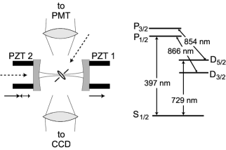
The experimental setup is schematically shown in Fig. 1. The 3-dimensional RF-Paul trap consists of an elliptical ring electrode with average diameter of 1.4 mm and two endcaps with a spacing of 1.2 mm (material: 0.2 mm molybdenum wire). The secular frequencies are MHz at a rf drive field power of 1 W. Here, denotes the direction of the trap axis, which is at 45∘ to the cavity axis. The and radial directions both include an angle of with the plane spanned by cavity and trap axis. A magnetic field of 3 G perpendicular to the cavity axis provides a quantization axis and a frequency splitting of Zeeman components of the S1/2 – D5/2 transition. Calcium ions are loaded into the trap from a thermal atom beam by a two-step photoionization process using diode lasers near 423 nm and 390 nm GuldePhotoion . The trap is placed in the center of a near-confocal resonator with finesse at 729 nm, waist radius m, mirror separation mm and radius of curvature mm. Cylindrical piezoceramics (PZT) allow fine-tuning of the cavity length across approx. 1.5 free spectral ranges.
The coherent coupling of the ion to the cavity field is measured in three steps:
(i) Preparation: First we use Doppler cooling on the S1/2 – P1/2 transition at 397 nm (see Fig. 1) to cool the ion into the Lamb-Dicke regime. A repumper laser at 866 nm inhibits optical pumping into the D3/2 level. From coherent dynamics (Rabi oscillations) on the carrier and first motional sidebands Roos99 we determine the mean vibrational quantum numbers after Doppler cooling to be . From these mean phonon numbers and the secular frequencies given above we calculate an rms extension of the ion’s motional wave packet of 26 nm in direction of the cavity axis, much smaller than the wavelength of 729 nm. After cooling, the ion is prepared in the S substate by optical pumping with radiation at 397 nm.
(ii) Interaction: The laser at 729 nm is set to a fixed detuning from the S1/2 – D5/2 ( to ) qubit transition. We inject the laser light into the TEM00 mode of the cavity and scan the cavity with a voltage ramp applied to one of the PZTs (scan PZT). When the cavity reaches resonance with the laser frequency it fills with light and the ion is excited. A constant voltage is applied to the other PZT (offset PZT) that determines the ion’s position relative to the SW field.
(iii) State analysis: The final step is state detection by electron shelving. Fluorescence on the S1/2 – P1/2 dipole transition at 397 nm is used to discriminate with high efficiency () between excited state (electron shelved in D5/2, no fluorescence) and ground state (fluorescence).
In order to obtain an excitation spectrum, the 729 nm laser is tuned over the quadrupole transition in steps of about 1 kHz. For any given laser detuning the sequence (i)-(iii) is repeated 100 times to determine the excitation probability.
In our first experiment we probe the ion’s response to temporal variations of the intracavity field by placing it close to a node of the SW field quadrupole and varying the cavity scan rate. The sign of the voltage ramp applied to the scan PZT determines whether the scan mirror moves towards the offset mirror or away from it. For a negative (positive) scan rate, i.e. mirrors moving towards each other (apart), the intracavity field is Doppler blue (red) shifted and thus the excitation spectrum will be red (blue) shifted, as the excitation laser detuning has to compensate for the Doppler shift. The scan velocity is expressed in units of a normalized scan rate RohdeCavity ; LawrenceCavity , corresponding to the frequency shift in units of HWHM cavity linewidths per cavity storage time: , with laser frequency , cavity length variation and cavity (energy) storage time .
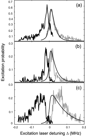
The experimental results for scan rates are shown in Fig. 2. The excitation spectra show the expected blue shift (red shift) for increasing positive (negative) scan rates and a broadening due to the Doppler effect. An excitation probability of more than 0.5 as in Fig. 2(a) clearly demonstrates that the ion is coherently interacting with the intracavity field. We theoretically model the excitation for different laser detunings by numerically integrating 2-level Bloch-equations using the time-dependent intracavity field calculated from the pertaining differential equations RohdeCavity ; LawrenceCavity . The results of the theoretical simulation for positive scan rates are shown as solid lines superimposed on the blue shifted spectra in Fig. 2. The calculated and experimental spectra show good agreement for small scan rates (Fig. 2(a,b)). For larger scan rates (Fig. 2(c)) the centers of the spectra are slightly shifted. We assume that this shift is caused by nonlinearities and hysteresis effects of the PZT motion. Although we kept the excitation power constant in the experiments, we left the Rabi frequency as fit parameter to account for variations in excitation due to thermal drift of the cavity shifting the node of the SW away from the ion’s position.
The second type of experiment probes the ion’s response to spatial field variations. For this, we leave the scan rate fixed at a small value, allowing for stable scans with only little perturbations of the excitation spectrum, as in Fig. 2(a). The intensity of the 729 nm laser is adjusted such that the excitation is kept well below saturation. The offset voltage of both scan PZT and offset PZT is then varied simultaneously in such a way that the SW in the cavity is shifted longitudinally with respect to the location of the ion. The position-dependent excitation probability is determined by fitting each excitation spectrum with a Lorentzian and adopting the peak value. Fig. 3 displays these values as function of the PZT offset voltage.
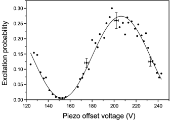
Error bars given for representative data points in Fig. 3 are due to PZT hysteresis (abscissa) and the errors of the fits to the excitation spectra (ordinate). The excitation probability varies spatially with the intensity of the SW quadrupole . A theoretical Bloch-equation analysis as described above predicts a nearly pure sin2 spatial variation, deviating by less than 1%. From a sin2 fit to the data points we obtain the contrast ratio (visibility ) of the position-dependent excitation, . This very high visibility results from the strong confinement of the ion’s wavefunction: the laser-cooled ion, oscillating with its secular frequencies and with thermally distributed amplitudes, has a mean spatial extension along the cavity axis of nm. The thermal oscillations lead to a calculated reduction of the excitation contrast by a factor of , compared to the excitation contrast experienced by a point-like atom at rest. Thus, the experimentally determined visibility and the theoretical estimate agree very well.
A necessary condition for all experiments relying on ion-cavity mode coupling is the ability to place the ion at a certain position of the intracavity SW field with high precision and high reproducibility GuthoehrleinNature . In our experiment, the precision of positioning the center of the ion’s wavefunction, using a measurement as in Fig. 3, is limited by the uncertainty in the measured excitation probability. This uncertainty is due to a statistical error, i.e. the finite number of state detection measurements, and systematic errors such as fluctuations of laser intensity and wavelength, drift and jitter of scan PZT etc. EschnerBarium . From the uncertainties in excitation probability (error bars in Fig. 3) we deduce a spatial precision between 7 nm () at the position of largest slope and 12 nm and 36 nm at minimum or maximum excitation, respectively. We note, however, that the precision can be enhanced by averaging over a larger number of state detection measurements.
Many schemes for quantum information processing with trapped ions rely on coherent interaction not only with the internal state but also with the motional degrees of freedom. A controlled coupling to the motional quantum state is a precondition for realizing such schemes.
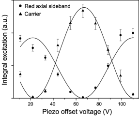
In order to demonstrate this motion-dependent coupling, we recorded excitation probabilities of the ion at a fixed cavity scan rate (), for different positions within the SW, and with the laser at 729 nm now tuned to either the carrier (no change of vibrational quantum number, ) or the red axial sideband (, laser detuned by ) of the S1/2 – D5/2 transition. In both cases, the intensity of the laser was adjusted such that the excitations of carrier and sideband were comparable and were kept well below saturation. In this experiment we determine the integral excitation, i.e. the area of the respective excitation spectra, as the spectra show an asymmetric line shape (c.f. Fig. 2(b,c)). As displayed in Fig. 4, carrier and sideband excitations both map the SW spatial field variation, but the traces are shifted by a phase factor of . This phase shift arises due to symmetry characteristics of the transition matrix elements of carrier and sideband transitions in a SW field CiracStandWave ; SasuraReview : The spatial part of the quadrupole transition matrix element is proportional to for a travelling wave (TW) and for a SW with the electric field quadrupole . Here and are the vibrational quantum numbers in the S1/2 and D5/2 level, respectively, is the wavenumber and is the ion’s position in the field. For a TW, all vibrational states can be coupled as contains even and odd powers of . In contrary, for a SW has to be expanded into even or odd powers of depending on the ion’s position, e.g. close to a node or close to an anti-node. Thus, transitions changing the phonon number by even or odd integers can only be excited at different positions in the SW. The red sideband transition () couples maximally at anti-nodes of the SW, whereas the carrier transition () couples maximally at nodes.
The high-contrast orthogonal coupling of carrier and sideband transitions to the cavity mode facilitates applications such as cavity-assisted cooling in a SW CiracStandWave or the Cirac-Zoller quantum-computing scheme CiracZoller95 . Both schemes rely on driving vibrational sideband transitions and benefit from suppressing off-resonant carrier transitions which induce motional heating or impose a limit on the attainable gate speed Steane00 , respectively. Furthermore, the ion-cavity coupling allows for demonstrating and utilizing cavity-modified spontaneous emission: we calculate the cooperativity parameter , with our experimental ion-field coupling constant 134 Hz, cavity decay rate 102 kHz and spontaneous emission rate 0.17 Hz. Due to the coupling, the spontaneous emission rate is enhanced by the Purcell factor and the fraction of spontaneous emission from the D5/2 level emitted into the cavity mode is . This is sufficient for demonstrating cavity-assisted cooling via destructive quantum interference of heating transitions CiracBadCavity , or triggered single photon emission from the D5/2 level. Improvement of the latter scheme and realization of the atom-photon interface CiracNetwork can be readily achieved by employing an adiabatic transfer technique LawSinglePhotons ; HennrichPassage and using a cavity with higher finesse ().
In summary we have demonstrated coherent coupling of electronic and motional states of a single trapped ion to a single field mode of a high finesse cavity. The position of the ion within the standing wave can be determined with a precision of up to . As the electronic quadrupole transition in Ca+ is one of the candidates for implementing a quantum bit, our experiments are a key step towards realization of quantum computing and communication schemes with trapped ions that require a controlled interaction of ion and cavity field.
This work is supported by the Austrian ’Fonds zur Förderung der wissenschaftlichen Forschung’ (SFB15), by the European Commission (TMR networks ’QI’ and ’QSTRUCT’ (ERB-FRMX-CT96-0087 and -0077), IHP network ’QUEST’ (HPRN-CT-2000-00121) and IST/FET program ’QUBITS’ (IST-1999-13021)), and by the ”Institut für Quanteninformation GmbH”.
References
- (1) H.C. Nägerl et al., Phys. Rev. A 61, 023405 (2000).
- (2) J.I. Cirac et al., Phys. Rev. Lett. 78, 3221 (1997).
- (3) G.R. Guthöhrlein et al., Nature 414, 49 (2001).
- (4) C.K. Law and H.J. Kimble, J. Mod. Opt. 44, 2067 (1997).
- (5) M. Hennrich et al., Phys. Rev. Lett. 85, 4872 (2000).
- (6) K.M. Gheri et al., Phys. Rev. A 58, R2627 (1998).
- (7) D.M. Meekhof et al., Phys. Rev. Lett. 76, 1796 (1996).
- (8) Ch. Roos et al., Phys. Rev. Lett. 83, 4713 (1999).
- (9) V. Bužek et al., Phys. Rev. A 56, 2352 (1997).
- (10) F.L. Semião, A. Vidiella-Barranco, and J.A. Roversi, Phys. Rev. A 64, 024305 (2001).
- (11) J.I. Cirac et al., Phys. Rev. A 46, 2668 (1992).
- (12) J.I. Cirac, M. Lewenstein, and P. Zoller, Phys. Rev. A 51, 1650 (1995).
- (13) V. Vuletić, H.W. Chan, and A.T. Black, Phys. Rev. A 64, 033405 (2001).
- (14) W. Paul, Rev. Mod. Phys. 62, 531 (1990).
- (15) H. Dehmelt, Bull. Am. Phys. Soc. 20, 60 (1975).
- (16) S. Gulde et al., Appl. Phys. B 73, 861 (2001).
- (17) Note, that the atomic quadrupole moment couples to the gradient of the electric field. The maximum excitation thus occurs at the nodes of the standing wave.
- (18) H. Rohde et al., J. Opt. Soc. Am. B 19, 1425 (2002).
- (19) M.J. Lawrence et al., J. Opt. Soc. Am. B 16, 523 (1999).
- (20) J. Eschner et al., Nature 413, 495 (2001).
- (21) M. Šašura and V. Bužek, submitted to J. Mod. Opt., eprint arXiv:quant-ph/0112041.
- (22) J.I. Cirac and P. Zoller, Phys. Rev. Lett. 74, 4091 (1995).
- (23) A. Steane et al., Phys. Rev. A 62, 042305 (2000).