High contrast Mach-Zehnder lithium atom interferometer in the Bragg regime
Abstract
We have constructed an atom interferometer of the Mach-Zehnder type, operating with a supersonic beam of lithium. Atom diffraction uses Bragg diffraction on laser standing waves. With first order diffraction, our apparatus has given a large signal and a very good fringe contrast (%), which we believe to be the highest ever observed with thermal atom interferometers. This apparatus will be applied to high sensitivity measurements.
pacs:
03.75.Dg,32.80.Lg,39.20.+qSeveral different atom interferometers gave their first signals in 1991 :
-
•
a Young’s double slit experiment was demonstrated by O. Carnal and J. Mlynek, with a supersonic beam of metastable helium carnal91
-
•
a Mach-Zehnder interferometer built by D. Pritchard and coworkers using a thermal atomic beam of sodium and diffraction on material gratings keith91
- •
-
•
an interferometer using laser cooled sodium atom and Raman diffraction was built by M. Kasevich and S. Chu and gave the first high sensitivity measurement of the local acceleration of gravity based on atom interferometry kasevich91
This research field has developed rapidly since 1991 and an excellent overview of this field and of its applications can be found in the book ”Atom interferometry” berman97 .
In this paper, we describe the first interference signals observed with our newly built Mach-Zehnder atom interferometer operating with thermal lithium atoms. The diffraction gratings, which are used as mirrors and beam-splitters, are made of laser standing waves operating in the Bragg regime. Our first signals present a very good signal to noise ratio, a mean detected atom flux of and a % fringe contrast. As far as we know, this is the highest contrast ever observed with a thermal atom Mach-Zehnder interferometer.
Let us recall the performances achieved by this family of atom interferometers. In each case, we give the mean value of the detected atomic flux and the fringe contrast (or visibility) . These parameters are both important for phase measurements : assuming a Poisson statistics for the noise, the accuracy of these measurements increases with a figure of merit given by . In 1991, the interferometer of D. Pritchard and coworkers keith91 gave a % contrast with a mean detected atom flux of , values improved in 1997 up to a % contrast and a mean flux of schmiedmayer97 or a % contrast and a mean flux of lenef97 . In 1995, A. Zeilinger and coworkers rasel95 operated an interferometer using metastable argon and laser diffraction in the Raman-Nath regime which produced a % contrast associated to a mean detected flux of . Also in 1995, S. A. Lee and coworkers giltner95b built an interferometer using metastable neon and laser diffraction in the Bragg regime and they observed a % contrast associated to a mean detected flux of . Finally, in 2001, an helium interferometer built by J.P. Toennies and coworkers toennies01 , with material gratings, has given a % contrast with a mean detected flux close to .
We have limited the present comparison to the family of interferometers which rely on elastic diffraction, i.e. in which the atom internal state is not modified by the diffraction process. However, as discussed by Ch. Bordé borde89 ; borde97 , the general case is inelastic diffraction, which is used in Ramsey-Bordé interferometers riehle91 and also in Mach-Zehnder atom interferometers. This type of interferometer can provide a very high output flux because the various outputs are distinguished by the atom internal state and not only by the direction of propagation : this circumstance permits to use a broad (but well collimated) atomic beam. One of the best examples is the cesium interferometer developed by Kasevich and coworkers as a gyroscope of extremely high sensitivity. This interferometer uses a thermal atomic beam of cesium, with transverse laser cooling and it has produced a fringe contrast of % gustavson97 , an output flux equal , and a signal to noise ratio of for s of integration gustavson00 . However, this advantage of Raman interferometers is obtained only if one does not separate the atomic paths in order to apply a perturbation to one of the two paths. This limitation is one of the reasons which explain why we have not chosen to develop a Raman interferometer.
When building an atom interferometer, two very important choices must be made, namely the atom and the diffraction process. The choice of the atom is largely limited by the possibility of producing either a very intense atomic beam or by the availability of a very high detection sensitivity. For thermal atoms, an efficient laser induced fluorescence detection is feasible gustavson97 ; gustavson00 but difficult because the time spent in the laser excitation volume is small. Another detection technique is based on surface ionization, which is very efficient only with alkali atoms or with metastable atoms. We have chosen to work with an alkali atom in its ground state, because the interactions of these atoms are more accurately described by ab initio quantum chemistry calculations than those of metastable rare gas atoms. Then, a very important design parameters is the first order diffraction angle (where is the grating period, the atomic mass and the velocity) as it defines the needed collimation of the atomic beam and also the separation of the atomic paths near the second grating. For supersonic beams of light alkalis seeded in a carrier gas, the beam velocity depends almost solely of the carrier gas molecular mass and a small velocity requires a heavy carrier gas. A convenient and inexpensive choice is argon, which gives close to m/s, for a temperature near K.
We may compare our choices to those of D. Pritchard, as our interferometer design is largely inspired by his design. The choices made by D. Pritchard were to use material gratings with very small value, nm in most experiments (but some experiments involved smaller values down to nm) and sodium atom (molar mass g), with a de Broglie wavelength pm and a first order diffraction angle rad. As further discussed below, we have made the choice of using laser diffraction and, in this case, the grating period is , where is the wavelength of the resonance transition. Usually, the first resonance transition is chosen for intensity reasons and practical considerations (laser cost, power and availability) and the achieved grating periods are not very small, in the nm range. For lithium, the value ( nm corresponding to nm), substantially larger than the value commonly used by D. Pritchard, is compensated by the smaller mass (molar mass g). With a de Broglie wavelength pm, the first order diffraction angle is rad (from now on, we will discuss only the case of 7Li which represents % of natural lithium and which is selected by our choice of laser frequency). We want to take advantage of this relatively large diffraction angle to make interferometric experiments, with only one atomic path submitted to a perturbation. Such experiments have been done only by the group of D. Pritchard ekstrom95 ; schmiedmayer95 , using a separation between the two atomic paths of the order of m near the second grating, while in our apparatus the corresponding separation is equal to m. Obviously, considerably larger separation values can be achieved by using a slow atomic beam, as produced by laser cooling, but, up to now, in cold atom interferometers, the various atomic paths have not been separated because of the size of the cold samples.
Laser diffraction of atoms results from the proposal of electron diffraction by light due to Kapitza and Dirac kapitza33 , generalized to atom diffraction by S. Altshuler et al. altshuler66 . In the Bragg geometry, the oscillating character of the electron diffraction amplitude appears in the work of M. Federov federov67 and R. Gush et al. gush71 . Early general theoretical analysis of laser diffraction of atoms are due to A. Bernhardt and B. Shore bernhardt81 as well as to Ch. Tanguy et al. tanguy84 . The Rabi-oscillation regime in the Bragg geometry was discussed by D. Pritchard and P. Gould in 1985 pritchard85 and observed by the same research group in 1987 martin88 . The interest of Bragg diffraction for interferometry is that the incident beam is split almost perfectly in only two beams giltner95a ; borde97 and the relative intensities of these two beams can be tuned at will by varying the laser power density and/or the interaction time. In a perturbation viewpoint, diffraction efficiency depends only of the product of these two parameters but, obviously, they are not equivalent keller99 ; champenois01 . Ideally, Bragg diffraction can provide the % beam splitters and % reflective mirrors needed to build a perfect Mach-Zehnder interferometer, with a % transmission. On the contrary, material gratings have a low diffraction efficiency in the non-zero orders and the transmission of this type of interferometer cannot exceed a few percent ekstrom93 . Moreover, in the case of the transition of lithium, the hyperfine structure of the excited state is very small. Then, provided that the laser detuning is large with respect to this structure and that the laser beam is linearly polarized, the potential seen by ground state atoms is independent of but still depends of the value because of the difference in detuning. In this case, the diffraction amplitude is the same for all the sublevels of one hyperfine level. For the experiments described below, the laser frequency is detuned on the blue side of the transition, the detuning being about and GHz for the and hyperfine states, respectively. With such a detuning, real excitation of an atom, while crossing a standing wave, has a low probability, of the order of a few percent, so that atomic diffraction is almost perfectly coherent.
A schematic drawing of our interferometer appears in figure 1. An atomic beam of lithium, strongly collimated by a two-slit system, crosses three laser standing waves, which play the role of beam splitters (first and third standing waves) and of mirrors (second standing wave). Diffraction of an atomic wave of vector by grating of wavevector produces a new wave of wavevector , where is the diffraction order. The two waves, exiting from the interferometer by the exit labeled in figure 1, have the wavevectors (upper path) and (lower path). If these two wavevectors were not equal, interference fringes would appear on the detector surface and integration over the detector area would wash out the expected interference signal. Therefore, we must cancel the quantity to optimize the fringe contrast. For a perfect interferometer champenois99 , the two beams labeled and carry complementary interference signals proportional to the quantities :
| (1) |
where is the coordinate of mirror producing the laser stationary wave and is the corresponding grating period, nm. Therefore, interference fringes can be observed by displacing anyone of the three mirrors in the -direction.

In our experiment, a supersonic beam of lithium seeded in argon (typical pressure mbar) is emitted by an oven : the temperature of the oven body fixes the lithium pressure to mbar at K (or mbar at K for some experiments), while the front part holding the m nozzle is overheated ( K) to prevent clogging. To insure the best stability, these temperatures are stabilized within K. The beam goes through a skimmer and enters a second vacuum chamber, where it reaches a collision-free zone. A third vacuum chamber holds the two-slit system used to strongly collimate the beam. In the fourth vacuum chamber, the atomic beam crosses three laser standing waves, each one being produced by reflecting a laser beam on a mirror , , the distance between consecutive standing waves being mm. One of the emerging atomic beams is then selected by a detector slit whose width and -position can be finely tuned under vacuum. Finally, this selected beam enters an UHV chamber through a mm diameter hole. This hole and the skimmer are the only collimating elements in the vertical -direction. The atoms are detected by a Langmuir-Taylor hot-wire detector using a rhenium ribbon and a channeltron. The UHV chamber is pumped by a l/s turbomolecular pump (base pressure mbar). The oven chamber is pumped by an unbaffled l/s oil diffusion pump, while all the other chambers are pumped by oil diffusion pumps, with water cooled baffles, providing a base pressure near mbar. Our Langmuir-Taylor hot-wire detector delhuille02 has a detection probability for lithium atom in the % range depending on rhenium surface oxidation and temperature and a background count rate of the order of a few thousand counts/s.
The alignment of the collimating elements is simplified thanks to a laser alignment done before operation. The three mirrors must be oriented within about microradians, in two directions and the final adjustments are made under vacuum by piezo mounts. The properties of a standing wave depend linearly on the orientation angles of the mirror used to reflect the laser beam, but are considerably less sensitive to the direction of this beam, which must be perpendicular to the mirror within milliradians only. We use mm diameter laser beams, produced by splitting the beam of an argon ion pumped cw single frequency dye laser, after expansion by a telescope.
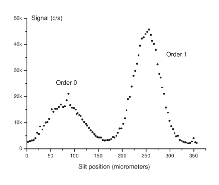
Figure 2 shows the profile of the lithium beam diffracted by the laser standing wave corresponding to mirror . This profile is recorded by moving the detector slit (slitwidth m). After fine tuning of the angle corresponding to the rotation of this mirror around the y-axis, we observe two well resolved peaks, corresponding to the diffraction orders zero and one. The order zero peak contains the undiffracted part of the 7Li levels and also the 6Li content of the beam for which the laser has little effect. Bragg diffraction is a Rabi-type oscillation between the two diffraction orders and the amplitude and the phase of this oscillation depend of the atom incidence angle and velocity, so that the observed diffraction efficiency results from an average over the initial conditions. ¿From the geometry of the experiment, we have verified that the distance between the two peaks is in excellent agreement with the calculated diffraction angle. The observation of diffraction by each of the three laser standing waves serves to optimize the angle of each of the three mirrors to fulfill Bragg condition.
We can then search for interference signals, by running simultaneously the three standing waves with incident laser powers equal to , and mW respectively, corresponding to an ideal Mach-Zehnder design. Using an autocollimator, we set the orientation angles of the three mirrors so that the vector normal to each mirror is horizontal within rad. As explained above, we must cancel the quantity and this is done by acting on one of the three mirrors, in order to optimize the fringe contrast.
In several previous apparatuses keith91 ; schmiedmayer97 ; giltner95b , the vibrational noise on the grating -positions induced a large phase noise in the interferometer, so that it was necessary to measure and reduce this vibrational noise before any observation. A three-grating Mach-Zehnder optical interferometer linked to the gratings can be used for this purpose keith91 ; giltner95b , as first done for a neutron interferometer by M. Gruber et al. gruber89 . We have also built a similar optical interferometer. Its output signal is given by equation (1), being now the optical gratings period ( m in our experiment). In our interferometer, the detected part of the vibration-induced motion of the three mirrors has a rms value equal to nm in a kHz bandwidth. This very small vibrational noise is due to our construction (the interferometer mirrors are on a very rigid bench inside the vacuum chambers, which are placed on a massive support located in the basement). As the resulting phase noise, rad, induces a negligible contrast loss, we have not tried to reduce this noise by a feedback loop.
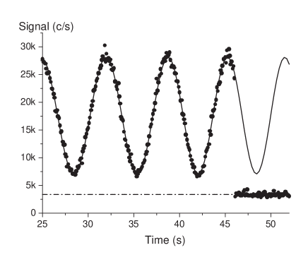
The detector slit , with a width m, has been put at exit or at exit (see figure 1) with similar results. A slightly better fringe contrast is obtained at exit than at exit , probably because of different contributions of stray atomic beams in the two cases. The main stray beams, which are not represented in figure 1, correspond to the neglected diffraction orders : they should vanish exactly if the laser power densities and the interaction times were perfectly tuned and if there was no angular and velocity dispersion of the incident atomic beam. Figure 3 presents an example of experimental signal collected at exit with a counting period equal to s. If we substract the background which has an average value of counts/second, we estimate the fringe contrast by :
A simulation of our interferometer (as in our paper champenois99 , but using the Bragg diffraction amplitudes corresponding to an ideal interferometer) predicts a contrast near %, limited by the overlap of the exit beams and (see figure 1). The difference between this simulation and our experiment is parly due to stray beams, partly due to some phase dispersion in the interferometer. Assuming that the dominant effect is due to phase dispersion, with a Gaussian distribution and a rms value , the contrast is reduced by the factor . We thus deduce rad : in the language of usual optics, the rms value of the wavefront defects is equal to , where is the atom wavelength close to picometer!
Finally, we have measured the phase sensitivity of our experimental signal near mrad, not far from the shot-noise limit mrad deduced from the signal and background count rates.
As a conclusion, we have built and operated a Mach-Zehnder Bragg atom interferometer with lithium and obtained first interference signals with an excellent signal to noise ratio and a high fringe contrast, equal to %. Our simulations indicate that the present fringe contrast can be improved and we expect to do so in a near future. The contrast we have observed is comparable to the contrast observed with most cold atom interferometers (for instance kasevich91 ; peters99 ). However, a contrast of nearly % has been achieved in a Mach-Zehnder Bragg interferometer using a Bose-Einstein condensate as the atomic source torii00 . It is also interesting to compare our results with neutron interferometers. The technique to build such interferometers is now mature and recently built neutron interferometers gilliam99 ; kroupa00 exhibit a fringe contrast near %, while a % contrast was already observed in 1978 bauspiess78 . These very nice results suggest that an extremely high contrast is feasible. Unfortunately, the interactions of neutrons and atoms with matter and fields are extremely different so that the know-how established with neutrons is not easily transferred to atom interferometers.
We expect to optimize our setup, in particular to increase the beam intensity by various means, including transverse laser cooling. It will also be possible to work separately with both lithium isotopes, a very interesting possibility for some applications. In our interferometer, the two atomic paths are separated by m near the second standing wave and this distance is substantially larger than in previous atom interferometers and even larger separations have been achieved by the group of Toennies toennies01 . With this new generation of interferometers, very sensitive measurements of weak perturbations are possible : with an interaction time of the order of s and a minimum detectable phaseshift of the order of mrad (which seems within reach, after some optimization, with an integration time of the order of a few hours), a perturbation as small as eV can be detected. This extreme sensitivity will be used to measure atomic polarizability, index of refraction of gases for atomic waves, following the previous works of Pritchard’s group schmiedmayer97 ; ekstrom95 ; schmiedmayer95 .
I acknowledgement
We are very much indebted to the technical staff of our laboratory, M. Gianesin, D. Castex, P. Paquier, T. Ravel, A. Pellicer, L. Polizzi, W. Volondat, for their help in building the interferometer and to several students, A. Miffre, Th. Lahaye, E. Lavallette, R. Saers, B. Aymes, J. de Lataillade, for their contribution to the experiments. It is a pleasure to thank various colleagues, A. Bordenave-Montesquieu, J. F. Fels, J. P. Gauyacq, Siu Au Lee, H. J. Loesch, J. P. Toennies and J. P. Ziesel for their help and advice, and the ” Pôle Optique et Vision ” (Saint Etienne) for laser machining of our collimating slits. Région Midi Pyrénées is gratefully acknowledged for financial support. We also thank CNRS/SPM for financial support and for a temporary position given to one of us (L.J.).
References
- (1) O. Carnal and J. Mlynek, Phys. Rev. Lett. 66, 2689 (1991)
- (2) D. W. Keith, C. R. Ekstrom, Q. A. Turchette and D. E. Pritchard, Phys. Rev. Lett. 66, 2693 (1991)
- (3) Ch. J. Bordé, Phys. Lett. A 140, 10 (1989)
- (4) F. Riehle, Th. Kisters, A. Witte, J. Helmcke and Ch. J. Bordé, Phys. Rev. Lett. 67, 177 (1991)
- (5) M. Kasevich and S. Chu, Phys. Rev. Lett. 67, 181 (1991)
- (6) Atom interferometry edited by P. R. Berman (Academic Press 1997)
- (7) J. Schmiedmayer, M. S. Chapman, C. R. Ekstrom, T. D. Hammond, D. A. Kokorowski, A. Lenef, R.A. Rubinstein, E. T. Smith and D. E. Pritchard, in reference 1, p 1
- (8) A. Lenef, T. D. Hammond, E. T. Smith, M. S. Chapman, R. A. Rubenstein and D. E. Pritchard, Phys. Rev. Lett., 78, 760 (1997)
- (9) E. M. Rasel, M. K. Oberthaler, H. Batelaan, J. Schmiedmayer and A. Zeilinger, Phys. Rev. Lett., 75, 2633 (1995)
- (10) D.M. Giltner, R. W. McGowan and Siu Au Lee, Phys. Rev. Lett., 75, 2638 (1995)
- (11) J. P. Toennies, private communication (2001)
- (12) Ch. J. Bordé in reference 4, p 257
- (13) T. L. Gustavson, P. Bouyer and M. A. Kasevich, Phys. Rev. Lett., 78, 2046 (1997)
- (14) T. L. Gustavson, A. Landragin and M. A. Kasevich, Class. Quantum Grav., 17, 2385 (2000)
- (15) C. R. Ekstrom, J. Schmiedmayer, M. S. Chapman, T. D. Hammond and D. E. Pritchard, Phys. Rev. A 51, 3883 (1995)
- (16) J. Schmiedmayer, M. S. Chapman, C. R. Ekstrom, T. D. Hammond, S. Wehinger and D. E. Pritchard, Phys. Rev. Lett., 74, 1043 (1995)
- (17) P. L. Kapitza and P. A. M. Dirac, Proc. Cambridge Phil. soc. 29, 297 (1933)
- (18) S. Altshuler, L. M. Frantz and R. Braunstein, Phys. Rev. Lett., 17, 231 (196)
- (19) M. V. Federov, Sov. Phys. JETP, 25, 952 (1967)
- (20) R. Gush and H. P. Gush, Phys. Rev. D 3, 1712 (1971)
- (21) A. F. Bernhardt and B. W. Shore, Phys. Rev. A 23, 1290 (1981)
- (22) C. Tanguy, S. Reynaud and C. Cohen-Tannoudji, J. Phys. B: At. Mol. Phys. 17, 4623 (1984)
- (23) D. E. Pritchard and P. L. Gould, J. Opt. Soc. Am. B 2, 1799 (1985)
- (24) P. J. Martin, B. G. Oldaker, A. H. Miklich and D. E. Pritchard, Phys. Rev. Lett., 60, 515 (1988)
- (25) D.M. Giltner, R. W. McGowan and Siu Au Lee, Phys. Rev., A 52, 3966 (1995)
- (26) C. Keller, J. Schmiedmayer, A. Zeilinger, T. Nonn, S. Dürr, G. Rempe, Appl. Phys. B 69, 303 (1999)
- (27) C. Champenois et al., Eur. Phys. J. D 13, 271 (2001)
- (28) C. R. Ekstrom, Ph. D., MIT (1993) unpublished
- (29) C. Champenois, M. Büchner and J. Vigué, Eur. Phys. J. D 5, 363 (1999)
- (30) R. Delhuille et al., submitted to Rev. Scient. Instr.
- (31) M. Gruber, K. Eder, A. Zeilinger, R. Gahler and W. Mampe, Phys. Lett. A 140 , 363 (1989)
- (32) A. Peters, K. Y. Chung and S. Chu, Nature 400, 849 (1999)
- (33) Y. Torii, Y. Suzuki, M. Kozuma, T. Sugiura, T. Kuga, L. Deng and E. W. Hagley, Phys. Rev. A 61, 041602(R) (2000)
- (34) D. M. Gilliam, M. Arif, D. L. Jacobson and A. Ioffe, Nucl. Instr. and Meth. A422, 41 (1999)
- (35) G. Kroupa et al., Nucl. Instr. and Meth. A440, 604 (2000) and H. Rauch, private communication (2001)
- (36) W. Bauspiess, U. Bonse and H. Rauch, Nucl. Instr. and Meth. 157, 495 (1978)